In this tutorial, we will learn how to interface a 4×3 keypad with STM32 Blue Pill and program it in STM32CubeIDE using HAL libraries. A keypad is an input device that is used to give commands to other devices, from calculators to computers; input is given through the keypad. At first, we will briefly introduce you to the keypad, show its working principle, then interface it with our STM32 and program it to determine the key pressed using STMCube IDE. For demonstration, we will control four LEDs with the keys 1-8 by turning them on/off through each key.
Recommended Components
The following components are used in this project or are helpful for getting started with STM32 Blue Pill development.
| Component | How it’s used in this project | Buy on Amazon |
|---|---|---|
| STM32F103C8T6 Blue Pill Board | The STM32 board reading the keypad and driving the LEDs. | Check Price |
| ST-Link V2 Programmer | SWD programmer/debugger used to flash code onto the Blue Pill. | Check Price |
| 4×3 Membrane Keypad | The matrix keypad used as the input device. | Check Price |
| 5mm LEDs | Four LEDs controlled by the keypad keys. | Check Price |
| Resistor Kit (incl. 220Ω) | Four 220Ω current-limiting resistors for the LEDs. | Check Price |
| Breadboard & Jumper Wires | For wiring the keypad and LEDs to the Blue Pill. | Check Price |
As an Amazon Associate we earn from qualifying purchases. Prices and availability are accurate as of the date/time indicated and are subject to change.
We have similar guides for keypads with other microcontrollers also:
- 4×4 Keypad Interfacing with TM4C123 Tiva Launchpad
- KEYPAD INTERFACING 8051 MICROCONTROLLER with code
- 4×4 keypad Interfacing with Arduino
- KEYPAD INTERFACING WITH PIC16F877A MICROCONTROLLER
Keypads Introduction
Keypads consist of push buttons arranged in row and column patterns. That means if we take an example of a 4×4 keypad, it will internally consist of 16 push buttons. To save microcontroller pins, keypads are arranged in the form matrix of rows and columns. For instance, a 4×4 keypad is arranged into a matrix of four rows and four columns. By using this pattern, we will need only 8 GPIO pins of the microcontroller.
Keypad Pinout and Internal Structure
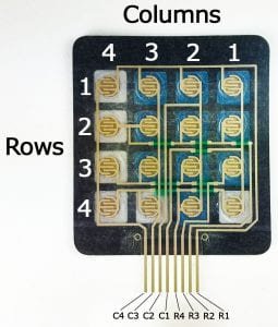
The diagram below shows two types of keypads available in the market. 4×3 keypad which has 4 rows and 3 columns and 4×4 keypad which has 4 rows and four columns.

The output connector provides output pins for rows and columns. The first four pins from the left are rows and the last four pins from the right are the columns for the 4×4 keypad. For the 4×3 keypad, the first four pins are from the left are rows and the last three pins from the right are the columns. To sense the state of each pushbutton from a specific location of a row and a column, we will use GPIO pins of STM32 Blue Pill as digital input pins.
Internally a keypad consists of push buttons. A 4×3 keypad consists of a matrix of 4×3 push buttons whereas a 4×4 keypad consists of a matrix of 4×4 push buttons. When a particular push button is pressed, a particular row and column make contact with each other. In other words, pressing a push button makes connection of one of the row lines with one of the column lines. It allows the current to pass between this row and column. This contact or current flow will be used to detect which particular key is pressed.
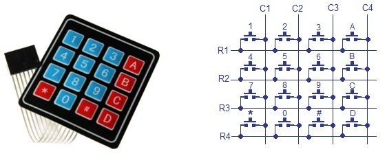
The status of each key/switch is determined by Scanning the rows or columns. The column pins (Col 1–Col4) are connected to the microcontroller as the inputs pins and the rows pins (Row 1–Row 4) are connected to the output pins of the microcontroller. Normally, all the column pins are pulled high by internal or external pull up resistors. Now we can read the status of each switch through scanning.
Scanning
Column pins are used as input pins, and rows pins are used as output. If low logic is given to all the Rows and high logic is given to each Column.
Find Column number
- When a switch/key is pressed, the corresponding row and column will get short.
- The output of the corresponding column goes to go low.
- Since we have made all the rows zero so this gives the column number of the pressed key.
Find Row number
- After the detection of the column number, the controller set’s all the rows to high.
- Each row is one by one set to zero by the microcontroller and the earlier detected column is checked and obviously, it becomes zero.
- The row due to which the column gets zero is the row number of the pressed key.
Interfacing 4×3 Keypad with STM32 Blue Pill for LED Control Project
We will need the following components for this project.
- STM32 Blue Pill board
- 4×3 Keypad
- Four 5mm LEDs
- Four 220 ohm resistors
- Breadboard
- Connecting Wires
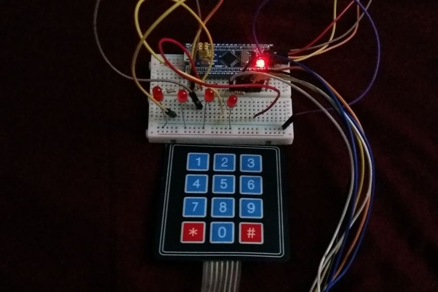
Assemble your circuit as shown in the connection diagram below:

We are using PB3-PB9 to connect with R1-C3 pins of the 4×3 keypad. Moreover, we have connected 4 LEDs with PB12-PB15 via 220 ohm current resistors respectively.
STM32 Blue Pill 4×3 Keypad Code to Control LEDs in STMCube IDE
We will use STM32Cube IDE to program our STM32 board. Open the IDE and head over to a new project.
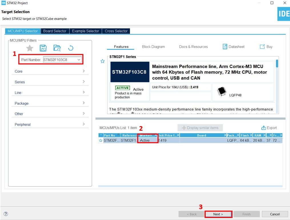
Then for the target selection, specify the STM32 Blue Pill board number. After that click on any column as shown in the picture below. Then click the ‘Next’ button.
Specify the name of your project then click ‘Finish’ to complete the setup of your project.
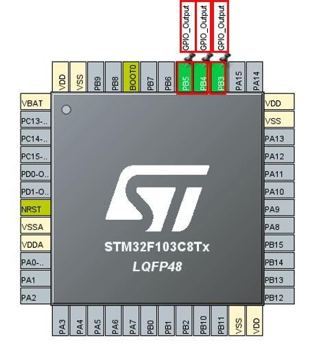
Setup PB3, PB4 and PB5 as GPIO_Output pins. These pins will be connected with R1-R3 pins of the keypad respectively.
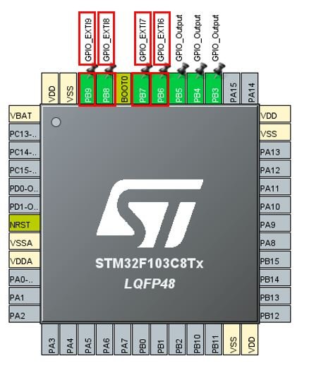
Next we select PB6, PB7, PB8 and PB9 as GPIO external interrupt pins. These pins will be connected with C1-C4 of the keypad respectively.
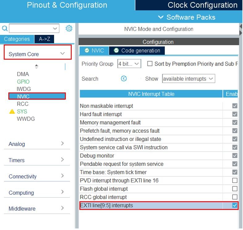
Now go to System Core > NVIC and enable the EXTI line [9:5] interrupts as shown below.
Moreover, we have configured PB12, PB13, PB14 and PB15 as GPIO_Output pins. Each of these GPIO pins will be connected with an LED which we will control via the keypad.

Now we will save our file. Press Ctrl + S. The following window will appear. Click ‘Yes.’ This will generate a template code for you.

Another window will appear that will ask if you want to open the perspective. Click ‘Yes.’

You can learn about STM32 GPIO pins in these in-depth guides:
- STM32 Blue Pill GPIO Pins with STM32Cube IDE: LED Blinking Tutorial
- STM32 Blue Pill External Interrupts with STM32Cube IDE and HAL Libraries
STM32 Blue Pill 4×3 Keypad Code to Control LEDs
When the user presses a key from the 4×3 keypad, the value held in the variable ‘pressed_key’ changes to the value of the key pressed. We will use keys 1-9 to control the four LEDs inside the HAL_GPIO_EXTI_Callback function. The table below shows the state of the LEDs when each key is pressed.
| STATE OF LED | KEY |
|---|---|
| LED1 (PB12) ON | 1 |
| LED1 OFF | 2 |
| LED2 (PB13) ON | 3 |
| LED2 OFF | 4 |
| LED3 (PB14) ON | 5 |
| LED3 OFF | 6 |
| LED4 (PB15) ON | 7 |
| LED4 OFF | 8 |
To find which key was pressed, we set the pins as external interrupt pins initially and then changed them to GPIO_Input pins to monitor which pin caused the interrupt.
Now let us look at our main.c file that was generated. Inside the main.c file, make sure the following code is part of your script by including the lines of code given below. We will use HAL library functions to control the GPIOs.
#include "main.h"

  GPIO_InitTypeDef GPIO_InitStructPrivate = {0};
  uint32_t previousMillis = 0;
  uint32_t currentMillis = 0;
  uint8_t pressed_key = 0;

void SystemClock_Config(void);
static void MX_GPIO_Init(void);

int main(void)
{
  HAL_Init();
  SystemClock_Config();
  MX_GPIO_Init();

  HAL_GPIO_WritePin(GPIOB, GPIO_PIN_3, 1);
  HAL_GPIO_WritePin(GPIOB, GPIO_PIN_4, 1);
  HAL_GPIO_WritePin(GPIOB, GPIO_PIN_5, 1);

  HAL_GPIO_WritePin(GPIOB, GPIO_PIN_12, 0);
  HAL_GPIO_WritePin(GPIOB, GPIO_PIN_13, 0);
  HAL_GPIO_WritePin(GPIOB, GPIO_PIN_14, 0);
  HAL_GPIO_WritePin(GPIOB, GPIO_PIN_15, 0);

  while (1)
  {

  }

}
Add the HAL_GPIO_EXTI_Callback function inside /* USER CODE BEGIN 4 */ /* USER CODE END 4 */
void HAL_GPIO_EXTI_Callback(uint16_t GPIO_Pin)
{
  currentMillis = HAL_GetTick();
  if (currentMillis - previousMillis > 10) {
    /*Configure GPIO pins : PB6 PB7 PB8 PB9 to GPIO_INPUT*/
    GPIO_InitStructPrivate.Pin = GPIO_PIN_6|GPIO_PIN_7|GPIO_PIN_8|GPIO_PIN_9;
    GPIO_InitStructPrivate.Mode = GPIO_MODE_INPUT;
    GPIO_InitStructPrivate.Pull = GPIO_NOPULL;
    GPIO_InitStructPrivate.Speed = GPIO_SPEED_FREQ_LOW;
    HAL_GPIO_Init(GPIOB, &GPIO_InitStructPrivate);

    HAL_GPIO_WritePin(GPIOA, GPIO_PIN_15, 0);
    HAL_GPIO_WritePin(GPIOB, GPIO_PIN_3, 1);
    HAL_GPIO_WritePin(GPIOB, GPIO_PIN_4, 0);
    HAL_GPIO_WritePin(GPIOB, GPIO_PIN_5, 0);
    if(GPIO_Pin == GPIO_PIN_6 && HAL_GPIO_ReadPin(GPIOB, GPIO_PIN_6))
    {
      pressed_key = 35; //ASCII value of #
    }
    else if(GPIO_Pin == GPIO_PIN_7 && HAL_GPIO_ReadPin(GPIOB, GPIO_PIN_7))
    {
      pressed_key = 57; //ASCII value of 9
      HAL_GPIO_WritePin(GPIOB, GPIO_PIN_15, 1);
    }
    else if(GPIO_Pin == GPIO_PIN_8 && HAL_GPIO_ReadPin(GPIOB, GPIO_PIN_8))
    {
      pressed_key = 54; //ASCII value of 6
      HAL_GPIO_WritePin(GPIOB, GPIO_PIN_14, 0);
    }
    else if(GPIO_Pin == GPIO_PIN_9 && HAL_GPIO_ReadPin(GPIOB, GPIO_PIN_9))
    {
      pressed_key = 51; //ASCII value of 3
      HAL_GPIO_WritePin(GPIOB, GPIO_PIN_13, 1);
    }

    HAL_GPIO_WritePin(GPIOA, GPIO_PIN_15, 0);
    HAL_GPIO_WritePin(GPIOB, GPIO_PIN_3, 0);
    HAL_GPIO_WritePin(GPIOB, GPIO_PIN_4, 1);
    HAL_GPIO_WritePin(GPIOB, GPIO_PIN_5, 0);
    if(GPIO_Pin == GPIO_PIN_6 && HAL_GPIO_ReadPin(GPIOB, GPIO_PIN_6))
    {
      pressed_key = 48; //ASCII value of 0
    }
    else if(GPIO_Pin == GPIO_PIN_7 && HAL_GPIO_ReadPin(GPIOB, GPIO_PIN_7))
    {
      pressed_key = 56; //ASCII value of 8
      HAL_GPIO_WritePin(GPIOB, GPIO_PIN_15, 0);
    }
    else if(GPIO_Pin == GPIO_PIN_8 && HAL_GPIO_ReadPin(GPIOB, GPIO_PIN_8))
    {
      pressed_key = 53; //ASCII value of 5
      HAL_GPIO_WritePin(GPIOB, GPIO_PIN_14, 1);
    }
    else if(GPIO_Pin == GPIO_PIN_9 && HAL_GPIO_ReadPin(GPIOB, GPIO_PIN_9))
    {
      pressed_key = 50; //ASCII value of 2
      HAL_GPIO_WritePin(GPIOB, GPIO_PIN_12, 0);
    }

    HAL_GPIO_WritePin(GPIOA, GPIO_PIN_15, 0);
    HAL_GPIO_WritePin(GPIOB, GPIO_PIN_3, 0);
    HAL_GPIO_WritePin(GPIOB, GPIO_PIN_4, 0);
    HAL_GPIO_WritePin(GPIOB, GPIO_PIN_5, 1);
    if(GPIO_Pin == GPIO_PIN_6 && HAL_GPIO_ReadPin(GPIOB, GPIO_PIN_6))
    {
      pressed_key = 42; //ASCII value of *
    }
    else if(GPIO_Pin == GPIO_PIN_7 && HAL_GPIO_ReadPin(GPIOB, GPIO_PIN_7))
    {
      pressed_key = 55; //ASCII value of 7
      HAL_GPIO_WritePin(GPIOB, GPIO_PIN_15, 1);
    }
    else if(GPIO_Pin == GPIO_PIN_8 && HAL_GPIO_ReadPin(GPIOB, GPIO_PIN_8))
    {
      pressed_key = 52; //ASCII value of 4
      HAL_GPIO_WritePin(GPIOB, GPIO_PIN_13, 0);
    }
    else if(GPIO_Pin == GPIO_PIN_9 && HAL_GPIO_ReadPin(GPIOB, GPIO_PIN_9))
    {
      pressed_key = 49; //ASCII value of 1
      HAL_GPIO_WritePin(GPIOB, GPIO_PIN_12, 1);
    }

    HAL_GPIO_WritePin(GPIOB, GPIO_PIN_3, 1);
    HAL_GPIO_WritePin(GPIOB, GPIO_PIN_4, 1);
    HAL_GPIO_WritePin(GPIOB, GPIO_PIN_5, 1);
    /*Configure GPIO pins : PB6 PB7 PB8 PB9 back to EXTI*/
    GPIO_InitStructPrivate.Mode = GPIO_MODE_IT_RISING;
    GPIO_InitStructPrivate.Pull = GPIO_PULLDOWN;
    HAL_GPIO_Init(GPIOB, &GPIO_InitStructPrivate);
    previousMillis = currentMillis;
  }
}
Working of the Code
Inside the main function, first all the peripherals are initialized, system clock is configured and all the configured peripherals are initialized.
  HAL_Init();
  SystemClock_Config();
  MX_GPIO_Init();
Initially, we set the state of all the GPIO pins connected with the column pins C1, C2 and C3 high. This is done by calling HAL_GPIO_WritePin() function. This function sets or clears the selected data port bit by taking in the selected GPIO peripheral as the first parameter, GPIO port bit as the second parameter and the pin state as the third parameter.
  HAL_GPIO_WritePin(GPIOB, GPIO_PIN_3, 1);
  HAL_GPIO_WritePin(GPIOB, GPIO_PIN_4, 1);
  HAL_GPIO_WritePin(GPIOB, GPIO_PIN_5, 1);
Moreover, we ensure all the four LEDs are initially off by configuring their state as low using HAL_GPIO_WritePin() function as well.
  HAL_GPIO_WritePin(GPIOB, GPIO_PIN_12, 0);
  HAL_GPIO_WritePin(GPIOB, GPIO_PIN_13, 0);
  HAL_GPIO_WritePin(GPIOB, GPIO_PIN_14, 0);
  HAL_GPIO_WritePin(GPIOB, GPIO_PIN_15, 0);
HAL GPIO EXTI Callback Function
Every time the keypad key is pressed, this callback function, HAL_GPIO_EXTI_Callback will execute and respond accordingly. This interrupt function will monitor whether there is an EXTI6-9 interrupt. If yes, then we will save the value of the key pressed in the variable ‘pressed_key’ and switch the state of the LEDs according to the key pressed.
void HAL_GPIO_EXTI_Callback(uint16_t GPIO_Pin)
{
  currentMillis = HAL_GetTick();
  if (currentMillis - previousMillis > 10) {

    GPIO_InitStructPrivate.Pin = GPIO_PIN_6|GPIO_PIN_7|GPIO_PIN_8|GPIO_PIN_9;
    GPIO_InitStructPrivate.Mode = GPIO_MODE_INPUT;
    GPIO_InitStructPrivate.Pull = GPIO_NOPULL;
    GPIO_InitStructPrivate.Speed = GPIO_SPEED_FREQ_LOW;
    HAL_GPIO_Init(GPIOB, &GPIO_InitStructPrivate);

    HAL_GPIO_WritePin(GPIOB, GPIO_PIN_3, 1);
    HAL_GPIO_WritePin(GPIOB, GPIO_PIN_4, 0);
    HAL_GPIO_WritePin(GPIOB, GPIO_PIN_5, 0);
    if(GPIO_Pin == GPIO_PIN_6 && HAL_GPIO_ReadPin(GPIOB, GPIO_PIN_6))
    {
      pressed_key = 35; //ASCII value of #
    }
    else if(GPIO_Pin == GPIO_PIN_7 && HAL_GPIO_ReadPin(GPIOB, GPIO_PIN_7))
    {
      pressed_key = 57; //ASCII value of 9
      HAL_GPIO_WritePin(GPIOB, GPIO_PIN_15, 1);
    }
    else if(GPIO_Pin == GPIO_PIN_8 && HAL_GPIO_ReadPin(GPIOB, GPIO_PIN_8))
    {
      pressed_key = 54; //ASCII value of 6
      HAL_GPIO_WritePin(GPIOB, GPIO_PIN_14, 0);
    }
    else if(GPIO_Pin == GPIO_PIN_9 && HAL_GPIO_ReadPin(GPIOB, GPIO_PIN_9))
    {
      pressed_key = 51; //ASCII value of 3
      HAL_GPIO_WritePin(GPIOB, GPIO_PIN_13, 1);
    }

    HAL_GPIO_WritePin(GPIOB, GPIO_PIN_3, 0);
    HAL_GPIO_WritePin(GPIOB, GPIO_PIN_4, 1);
    HAL_GPIO_WritePin(GPIOB, GPIO_PIN_5, 0);
    if(GPIO_Pin == GPIO_PIN_6 && HAL_GPIO_ReadPin(GPIOB, GPIO_PIN_6))
    {
      pressed_key = 48; //ASCII value of 0
    }
    else if(GPIO_Pin == GPIO_PIN_7 && HAL_GPIO_ReadPin(GPIOB, GPIO_PIN_7))
    {
      pressed_key = 56; //ASCII value of 8
      HAL_GPIO_WritePin(GPIOB, GPIO_PIN_15, 0);
    }
    else if(GPIO_Pin == GPIO_PIN_8 && HAL_GPIO_ReadPin(GPIOB, GPIO_PIN_8))
    {
      pressed_key = 53; //ASCII value of 5
      HAL_GPIO_WritePin(GPIOB, GPIO_PIN_14, 1);
    }
    else if(GPIO_Pin == GPIO_PIN_9 && HAL_GPIO_ReadPin(GPIOB, GPIO_PIN_9))
    {
      pressed_key = 50; //ASCII value of 2
      HAL_GPIO_WritePin(GPIOB, GPIO_PIN_12, 0);
    }

    HAL_GPIO_WritePin(GPIOB, GPIO_PIN_3, 0);
    HAL_GPIO_WritePin(GPIOB, GPIO_PIN_4, 0);
    HAL_GPIO_WritePin(GPIOB, GPIO_PIN_5, 1);
    if(GPIO_Pin == GPIO_PIN_6 && HAL_GPIO_ReadPin(GPIOB, GPIO_PIN_6))
    {
      pressed_key = 42; //ASCII value of *
    }
    else if(GPIO_Pin == GPIO_PIN_7 && HAL_GPIO_ReadPin(GPIOB, GPIO_PIN_7))
    {
      pressed_key = 55; //ASCII value of 7
      HAL_GPIO_WritePin(GPIOB, GPIO_PIN_15, 1);
    }
    else if(GPIO_Pin == GPIO_PIN_8 && HAL_GPIO_ReadPin(GPIOB, GPIO_PIN_8))
    {
      pressed_key = 52; //ASCII value of 4
      HAL_GPIO_WritePin(GPIOB, GPIO_PIN_13, 0);
    }
    else if(GPIO_Pin == GPIO_PIN_9 && HAL_GPIO_ReadPin(GPIOB, GPIO_PIN_9))
    {
      pressed_key = 49; //ASCII value of 1
      HAL_GPIO_WritePin(GPIOB, GPIO_PIN_12, 1);
    }

    HAL_GPIO_WritePin(GPIOB, GPIO_PIN_3, 1);
    HAL_GPIO_WritePin(GPIOB, GPIO_PIN_4, 1);
    HAL_GPIO_WritePin(GPIOB, GPIO_PIN_5, 1);

    GPIO_InitStructPrivate.Mode = GPIO_MODE_IT_RISING;
    GPIO_InitStructPrivate.Pull = GPIO_PULLDOWN;
    HAL_GPIO_Init(GPIOB, &GPIO_InitStructPrivate);
    previousMillis = currentMillis;
  }
}
First of all, we will configure the GPIO pins connected with the rows as input pins. These are the pins that we set in interrupt mode inside the configuration settings.
    GPIO_InitStructPrivate.Pin = GPIO_PIN_6|GPIO_PIN_7|GPIO_PIN_8|GPIO_PIN_9;
    GPIO_InitStructPrivate.Mode = GPIO_MODE_INPUT;
    GPIO_InitStructPrivate.Pull = GPIO_NOPULL;
    GPIO_InitStructPrivate.Speed = GPIO_SPEED_FREQ_LOW;
    HAL_GPIO_Init(GPIOB, &GPIO_InitStructPrivate);
Check Keys #, 9, 6 and 3
Now we set R1 pin to high state and R2 and R3 pins to low state and check for the interrupt if it occurred on PB6, PB7, P8 or P9. We use if-else if statements to check which key was pressed and set the variable ‘pressed_key’ to the ASCII value of the key. In this scenario, if the key with # is pressed, then the pressed_key holds the value 35. If the key with 9 is pressed, the pressed_key holds the value 57 and the led connected with PB15 turns on. Else the key with 6 is pressed, the pressed_key holds the value 54 and the led connected with PB14 turns off. Else the key with 3 is pressed, the pressed_key holds the value 51 and the led connected with PB13 turns on.
    HAL_GPIO_WritePin(GPIOB, GPIO_PIN_3, 1);
    HAL_GPIO_WritePin(GPIOB, GPIO_PIN_4, 0);
    HAL_GPIO_WritePin(GPIOB, GPIO_PIN_5, 0);
    if(GPIO_Pin == GPIO_PIN_6 && HAL_GPIO_ReadPin(GPIOB, GPIO_PIN_6))
    {
      pressed_key = 35; //ASCII value of #
    }which
    else if(GPIO_Pin == GPIO_PIN_7 && HAL_GPIO_ReadPin(GPIOB, GPIO_PIN_7))
    {
      pressed_key = 57; //ASCII value of 9
      HAL_GPIO_WritePin(GPIOB, GPIO_PIN_15, 1);
    }
    else if(GPIO_Pin == GPIO_PIN_8 && HAL_GPIO_ReadPin(GPIOB, GPIO_PIN_8))
    {
      pressed_key = 54; //ASCII value of 6
      HAL_GPIO_WritePin(GPIOB, GPIO_PIN_14, 0);
    }
    else if(GPIO_Pin == GPIO_PIN_9 && HAL_GPIO_ReadPin(GPIOB, GPIO_PIN_9))
    {
      pressed_key = 51; //ASCII value of 3
      HAL_GPIO_WritePin(GPIOB, GPIO_PIN_13, 1);
    }
Check Keys 0, 8, 5 and 2
Now we set R2 pin to high state and R1 and R3 pins to low state and check for the interrupt if it occurred on PB6, PB7, P8 or P9. We use if-else if statements to check which key was pressed and set the variable ‘pressed_key’ to the ASCII value of the key. In this scenario, if the key with 0 is pressed, then the pressed_key holds the value 48. If the key with 8 is pressed, the pressed_key holds the value 56 and the led connected with PB15 turns off. Else the key with 5 is pressed, the pressed_key holds the value 53 and the led connected with PB14 turns on. Else the key with 2 is pressed, the pressed_key holds the value 50 and the led connected with PB12 turns off.
HAL_GPIO_WritePin(GPIOB, GPIO_PIN_3, 0);
    HAL_GPIO_WritePin(GPIOB, GPIO_PIN_4, 1);
    HAL_GPIO_WritePin(GPIOB, GPIO_PIN_5, 0);
    if(GPIO_Pin == GPIO_PIN_6 && HAL_GPIO_ReadPin(GPIOB, GPIO_PIN_6))
    {
      pressed_key = 48; //ASCII value of 0
    }
    else if(GPIO_Pin == GPIO_PIN_7 && HAL_GPIO_ReadPin(GPIOB, GPIO_PIN_7))
    {
      pressed_key = 56; //ASCII value of 8
      HAL_GPIO_WritePin(GPIOB, GPIO_PIN_15, 0);
    }
    else if(GPIO_Pin == GPIO_PIN_8 && HAL_GPIO_ReadPin(GPIOB, GPIO_PIN_8))
    {
      pressed_key = 53; //ASCII value of 5
      HAL_GPIO_WritePin(GPIOB, GPIO_PIN_14, 1);
    }
    else if(GPIO_Pin == GPIO_PIN_9 && HAL_GPIO_ReadPin(GPIOB, GPIO_PIN_9))
    {
      pressed_key = 50; //ASCII value of 2
      HAL_GPIO_WritePin(GPIOB, GPIO_PIN_12, 0);
    }
Check Keys *, 7, 4 and 1
Now we set R3 pin to high state and R1 and R2 pins to low state and check for the interrupt if it occurred on PB6, PB7, P8 or P9. We use if-else if statements to check which key was pressed and set the variable ‘pressed_key’ to the ASCII value of the key. In this scenario, if the key with * is pressed, then the pressed_key holds the value 42. If the key with 7 is pressed, the pressed_key holds the value 55 and the led connected with PB15 turns on. Else the key with 4 is pressed, the pressed_key holds the value 52 and the led connected with PB13 turns off. Else the key with 1 is pressed, the pressed_key holds the value 49 and the led connected with PB12 turns on.
HAL_GPIO_WritePin(GPIOB, GPIO_PIN_3, 0);
    HAL_GPIO_WritePin(GPIOB, GPIO_PIN_4, 0);
    HAL_GPIO_WritePin(GPIOB, GPIO_PIN_5, 1);
    if(GPIO_Pin == GPIO_PIN_6 && HAL_GPIO_ReadPin(GPIOB, GPIO_PIN_6))
    {
      pressed_key = 42; //ASCII value of *
    }
    else if(GPIO_Pin == GPIO_PIN_7 && HAL_GPIO_ReadPin(GPIOB, GPIO_PIN_7))
    {
      pressed_key = 55; //ASCII value of 7
      HAL_GPIO_WritePin(GPIOB, GPIO_PIN_15, 1);
    }
    else if(GPIO_Pin == GPIO_PIN_8 && HAL_GPIO_ReadPin(GPIOB, GPIO_PIN_8))
    {
      pressed_key = 52; //ASCII value of 4
      HAL_GPIO_WritePin(GPIOB, GPIO_PIN_13, 0);
    }
    else if(GPIO_Pin == GPIO_PIN_9 && HAL_GPIO_ReadPin(GPIOB, GPIO_PIN_9))
    {
      pressed_key = 49; //ASCII value of 1
      HAL_GPIO_WritePin(GPIOB, GPIO_PIN_12, 1);
    }
We configure the R1-R3 pins to high state and set the C1-C4 pins back to EXTI.
    HAL_GPIO_WritePin(GPIOB, GPIO_PIN_3, 1);
    HAL_GPIO_WritePin(GPIOB, GPIO_PIN_4, 1);
    HAL_GPIO_WritePin(GPIOB, GPIO_PIN_5, 1);


    GPIO_InitStructPrivate.Mode = GPIO_MODE_IT_RISING;
    GPIO_InitStructPrivate.Pull = GPIO_PULLDOWN;
    HAL_GPIO_Init(GPIOB, &GPIO_InitStructPrivate);
    previousMillis = currentMillis;
main.c file
This is how a complete main.c file will be after modification.
#include "main.h"

  GPIO_InitTypeDef GPIO_InitStructPrivate = {0};
  uint32_t previousMillis = 0;
  uint32_t currentMillis = 0;
  uint8_t pressed_key = 0;

void SystemClock_Config(void);
static void MX_GPIO_Init(void);

int main(void)
{
  HAL_Init();
  SystemClock_Config();
  MX_GPIO_Init();

  HAL_GPIO_WritePin(GPIOB, GPIO_PIN_3, 1);
  HAL_GPIO_WritePin(GPIOB, GPIO_PIN_4, 1);
  HAL_GPIO_WritePin(GPIOB, GPIO_PIN_5, 1);

  HAL_GPIO_WritePin(GPIOB, GPIO_PIN_12, 0);
  HAL_GPIO_WritePin(GPIOB, GPIO_PIN_13, 0);
  HAL_GPIO_WritePin(GPIOB, GPIO_PIN_14, 0);
  HAL_GPIO_WritePin(GPIOB, GPIO_PIN_15, 0);

  while (1)
  {

  }

}

/**
  * @brief System Clock Configuration
  * @retval None
  */
void SystemClock_Config(void)
{
  RCC_OscInitTypeDef RCC_OscInitStruct = {0};
  RCC_ClkInitTypeDef RCC_ClkInitStruct = {0};

  /** Initializes the RCC Oscillators according to the specified parameters
  * in the RCC_OscInitTypeDef structure.
  */
  RCC_OscInitStruct.OscillatorType = RCC_OSCILLATORTYPE_HSI;
  RCC_OscInitStruct.HSIState = RCC_HSI_ON;
  RCC_OscInitStruct.HSICalibrationValue = RCC_HSICALIBRATION_DEFAULT;
  RCC_OscInitStruct.PLL.PLLState = RCC_PLL_NONE;
  if (HAL_RCC_OscConfig(&RCC_OscInitStruct) != HAL_OK)
  {
    Error_Handler();
  }
  /** Initializes the CPU, AHB and APB buses clocks
  */
  RCC_ClkInitStruct.ClockType = RCC_CLOCKTYPE_HCLK|RCC_CLOCKTYPE_SYSCLK
                              |RCC_CLOCKTYPE_PCLK1|RCC_CLOCKTYPE_PCLK2;
  RCC_ClkInitStruct.SYSCLKSource = RCC_SYSCLKSOURCE_HSI;
  RCC_ClkInitStruct.AHBCLKDivider = RCC_SYSCLK_DIV1;
  RCC_ClkInitStruct.APB1CLKDivider = RCC_HCLK_DIV1;
  RCC_ClkInitStruct.APB2CLKDivider = RCC_HCLK_DIV1;

  if (HAL_RCC_ClockConfig(&RCC_ClkInitStruct, FLASH_LATENCY_0) != HAL_OK)
  {
    Error_Handler();
  }
}

/**
  * @brief GPIO Initialization Function
  * @param None
  * @retval None
  */
static void MX_GPIO_Init(void)
{
  GPIO_InitTypeDef GPIO_InitStruct = {0};

  /* GPIO Ports Clock Enable */
  __HAL_RCC_GPIOB_CLK_ENABLE();

  /*Configure GPIO pin Output Level */
  HAL_GPIO_WritePin(GPIOB, GPIO_PIN_12|GPIO_PIN_13|GPIO_PIN_14|GPIO_PIN_15
                          |GPIO_PIN_3|GPIO_PIN_4|GPIO_PIN_5, GPIO_PIN_RESET);

  /*Configure GPIO pins : PB12 PB13 PB14 PB15
                           PB3 PB4 PB5 */
  GPIO_InitStruct.Pin = GPIO_PIN_12|GPIO_PIN_13|GPIO_PIN_14|GPIO_PIN_15
                          |GPIO_PIN_3|GPIO_PIN_4|GPIO_PIN_5;
  GPIO_InitStruct.Mode = GPIO_MODE_OUTPUT_PP;
  GPIO_InitStruct.Pull = GPIO_NOPULL;
  GPIO_InitStruct.Speed = GPIO_SPEED_FREQ_LOW;
  HAL_GPIO_Init(GPIOB, &GPIO_InitStruct);

  /*Configure GPIO pins : PB6 PB7 PB8 PB9 */
  GPIO_InitStruct.Pin = GPIO_PIN_6|GPIO_PIN_7|GPIO_PIN_8|GPIO_PIN_9;
  GPIO_InitStruct.Mode = GPIO_MODE_IT_RISING;
  GPIO_InitStruct.Pull = GPIO_NOPULL;
  HAL_GPIO_Init(GPIOB, &GPIO_InitStruct);

  /* EXTI interrupt init*/
  HAL_NVIC_SetPriority(EXTI9_5_IRQn, 0, 0);
  HAL_NVIC_EnableIRQ(EXTI9_5_IRQn);

}

void HAL_GPIO_EXTI_Callback(uint16_t GPIO_Pin)
{
  currentMillis = HAL_GetTick();
  if (currentMillis - previousMillis > 10) {
    /*Configure GPIO pins : PB6 PB7 PB8 PB9 to GPIO_INPUT*/
    GPIO_InitStructPrivate.Pin = GPIO_PIN_6|GPIO_PIN_7|GPIO_PIN_8|GPIO_PIN_9;
    GPIO_InitStructPrivate.Mode = GPIO_MODE_INPUT;
    GPIO_InitStructPrivate.Pull = GPIO_NOPULL;
    GPIO_InitStructPrivate.Speed = GPIO_SPEED_FREQ_LOW;
    HAL_GPIO_Init(GPIOB, &GPIO_InitStructPrivate);

    HAL_GPIO_WritePin(GPIOB, GPIO_PIN_3, 1);
    HAL_GPIO_WritePin(GPIOB, GPIO_PIN_4, 0);
    HAL_GPIO_WritePin(GPIOB, GPIO_PIN_5, 0);
    if(GPIO_Pin == GPIO_PIN_6 && HAL_GPIO_ReadPin(GPIOB, GPIO_PIN_6))
    {
      pressed_key = 35; //ASCII value of #
    }
    else if(GPIO_Pin == GPIO_PIN_7 && HAL_GPIO_ReadPin(GPIOB, GPIO_PIN_7))
    {
      pressed_key = 57; //ASCII value of 9
      HAL_GPIO_WritePin(GPIOB, GPIO_PIN_15, 1);
    }
    else if(GPIO_Pin == GPIO_PIN_8 && HAL_GPIO_ReadPin(GPIOB, GPIO_PIN_8))
    {
      pressed_key = 54; //ASCII value of 6
      HAL_GPIO_WritePin(GPIOB, GPIO_PIN_14, 0);
    }
    else if(GPIO_Pin == GPIO_PIN_9 && HAL_GPIO_ReadPin(GPIOB, GPIO_PIN_9))
    {
      pressed_key = 51; //ASCII value of 3
      HAL_GPIO_WritePin(GPIOB, GPIO_PIN_13, 1);
    }

    HAL_GPIO_WritePin(GPIOB, GPIO_PIN_3, 0);
    HAL_GPIO_WritePin(GPIOB, GPIO_PIN_4, 1);
    HAL_GPIO_WritePin(GPIOB, GPIO_PIN_5, 0);
    if(GPIO_Pin == GPIO_PIN_6 && HAL_GPIO_ReadPin(GPIOB, GPIO_PIN_6))
    {
      pressed_key = 48; //ASCII value of 0
    }
    else if(GPIO_Pin == GPIO_PIN_7 && HAL_GPIO_ReadPin(GPIOB, GPIO_PIN_7))
    {
      pressed_key = 56; //ASCII value of 8
      HAL_GPIO_WritePin(GPIOB, GPIO_PIN_15, 0);
    }
    else if(GPIO_Pin == GPIO_PIN_8 && HAL_GPIO_ReadPin(GPIOB, GPIO_PIN_8))
    {
      pressed_key = 53; //ASCII value of 5
      HAL_GPIO_WritePin(GPIOB, GPIO_PIN_14, 1);
    }
    else if(GPIO_Pin == GPIO_PIN_9 && HAL_GPIO_ReadPin(GPIOB, GPIO_PIN_9))
    {
      pressed_key = 50; //ASCII value of 2
      HAL_GPIO_WritePin(GPIOB, GPIO_PIN_12, 0);
    }

    HAL_GPIO_WritePin(GPIOB, GPIO_PIN_3, 0);
    HAL_GPIO_WritePin(GPIOB, GPIO_PIN_4, 0);
    HAL_GPIO_WritePin(GPIOB, GPIO_PIN_5, 1);
    if(GPIO_Pin == GPIO_PIN_6 && HAL_GPIO_ReadPin(GPIOB, GPIO_PIN_6))
    {
      pressed_key = 42; //ASCII value of *
    }
    else if(GPIO_Pin == GPIO_PIN_7 && HAL_GPIO_ReadPin(GPIOB, GPIO_PIN_7))
    {
      pressed_key = 55; //ASCII value of 7
      HAL_GPIO_WritePin(GPIOB, GPIO_PIN_15, 1);
    }
    else if(GPIO_Pin == GPIO_PIN_8 && HAL_GPIO_ReadPin(GPIOB, GPIO_PIN_8))
    {
      pressed_key = 52; //ASCII value of 4
      HAL_GPIO_WritePin(GPIOB, GPIO_PIN_13, 0);
    }
    else if(GPIO_Pin == GPIO_PIN_9 && HAL_GPIO_ReadPin(GPIOB, GPIO_PIN_9))
    {
      pressed_key = 49; //ASCII value of 1
      HAL_GPIO_WritePin(GPIOB, GPIO_PIN_12, 1);
    }

    HAL_GPIO_WritePin(GPIOB, GPIO_PIN_3, 1);
    HAL_GPIO_WritePin(GPIOB, GPIO_PIN_4, 1);
    HAL_GPIO_WritePin(GPIOB, GPIO_PIN_5, 1);
    /*Configure GPIO pins : PB6 PB7 PB8 PB9 back to EXTI*/
    GPIO_InitStructPrivate.Mode = GPIO_MODE_IT_RISING;
    GPIO_InitStructPrivate.Pull = GPIO_PULLDOWN;
    HAL_GPIO_Init(GPIOB, &GPIO_InitStructPrivate);
    previousMillis = currentMillis;
  }
}


/**
  * @brief  This function is executed in case of error occurrence.
  * @retval None
  */
void Error_Handler(void)
{
  /* USER CODE BEGIN Error_Handler_Debug */
  /* User can add his own implementation to report the HAL error return state */
  __disable_irq();
  while (1)
  {
  }
  /* USER CODE END Error_Handler_Debug */
}

#ifdef  USE_FULL_ASSERT
/**
  * @brief  Reports the name of the source file and the source line number
  *         where the assert_param error has occurred.
  * @param  file: pointer to the source file name
  * @param  line: assert_param error line source number
  * @retval None
  */
void assert_failed(uint8_t *file, uint32_t line)
{
  /* USER CODE BEGIN 6 */
  /* User can add his own implementation to report the file name and line number,
     ex: printf("Wrong parameters value: file %s on line %d\r\n", file, line) */
  /* USER CODE END 6 */
}
#endif /* USE_FULL_ASSERT */
Save the main.c file after modifying it. Now we are ready to build our project.
Building the Project
To build our project press Ctrl + B or go to Project > Build All.
Your project will start building. After a few moments, your project will be successfully built if there are no errors.
Connecting ST-Link Programmer with STM32
Now as we have successfully built our project let us move ahead and upload the code to our STM32 board. First, we will have to connect our Blue Pill STM32 with an ST-Link programmer. We will be using ST-Link V2.

This will provide an interface between our computer and our STM32 board. It consists of 10 pins. We will be using pin2 SWDIO, pin6 SWCLK, pin4 GND, and pin8 3.3V to connect with our STM32 board. The SWDIO is the data input/output pin and the SWCLK is the clock pin. Follow the pin configuration given on ST-LINK V2 to identify each pin.
Follow the table below to connect both devices correctly.
| STM32 | ST-LINK V2 |
| VCC 3.3V pin | pin8 3.3V |
| SWDIO pin | pin2 SWDIO |
| SWCLK pin | pin6 SWCLK |
| GND pin | pin4 GND |

Additionally, move the BOOT jumper to the right to enable the microcontroller to go into programming mode.

- Now connect your ST-LINK V2 with your computer via the USB port. Both devices will power ON.
- Next press the RUN button in the IDE. The ‘Edit configuration’ window will open up. Click ‘OK’.
- After a few moments, the code will be successfully sent to the STM32 board. Otherwise, press the RESET button on your STM32 board.
- Now to bring the Blue pill back to normal mode make sure you bring the BOOT jumper back at its place.
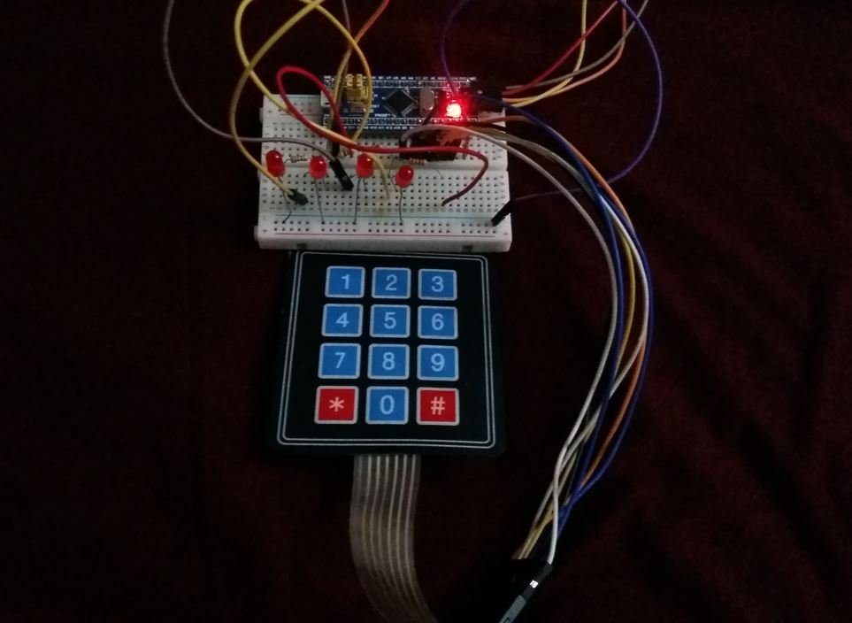
Demonstration
Once the code is uploaded to the board, start pressing the keys on the keypad. Press key 1 to turn the first LED on and press key 2 to turn it off. Press key 3 to turn the second LED on and press 4 to turn it off. Likewise, press key 5 to turn the third LED on and press 6 to turn it off. Press key 7 to turn the fourth LED on and press key 8 to turn it off.
You may also like to read: