In this tutorial, you will learn a very simple method of interfacing a keypad with a PIC microcontroller. Interfacing a keypad with any microcontroller such as PIC16F877A microcontroller involves connecting the keypad to the microcontroller’s GPIO pins and writing a program to read the keypad inputs. Therefore, you should know how to use GPIO pins of pic microcontroller. If you don’t know how to use GPIO pins of Pic microcontroller, you can follow this guide:
Before we begin with the lesson of keypad interfacing, it is assumed that you know how to interface an LCD with the PIC16F877A microcontroller. Because, we will be displaying keypad input on LCD. If you don’t know how to interface an LCD with the PIC16F877A microcontroller, check this article:

Demonstration Task
In this tutorial, we will interface a 4×4 matrix keypad with a PIC16F877A microcontroller and display the pressed digits or characters on an LCD using both the MikroC for PIC and MPLAB XC8 compilers.
We will see examples with MPLAB XC8 compiler and MikroC for Pic Compiler, we will utilize its user-friendly integrated development environment (IDE) to write and compile the code. The code will involve scanning each row of the keypad and detecting keypresses, and then displaying the corresponding characters on the LCD.
Keypad Introduction
A keypad is an input device that consists of a set of keys or buttons, usually arranged in a grid, which can be used for entering data or commands into a system. Keypads are commonly found in various electronic devices such as calculators, remote controls, security systems, and digital door locks. They provide a convenient and tactile interface for users to input numerical or alphanumeric data.
How a Keypad Works?
- Matrix Arrangement: Most keypads use a matrix arrangement where rows and columns intersect to form a grid of key positions. Each key is located at the intersection of a specific row and column.
- Switch Mechanism: Each key in the keypad has a switch mechanism beneath it. When a key is pressed, it makes an electrical connection between the corresponding row and column in the matrix.
- Row and Column Scanning: To determine which key is pressed, the microcontroller or dedicated keypad controller scans the rows and columns of the matrix. It energizes one row at a time and checks the status of the columns. If a key in the selected row is pressed, the microcontroller detects the electrical connection, identifies the corresponding column, and determines which key is pressed.
- Keypress Detection: The microcontroller reads the row and column information to identify the pressed key. The detected key can then be processed by the microcontroller to perform a specific action or send the corresponding data to a connected device.
- Output Signal: The output from the keypad is typically in the form of a key code or ASCII value corresponding to the pressed key. This output can be used by the embedded system or microcontroller to execute specific functions or display the entered data.
In summary, a keypad is a user interface device that relies on the detection of electrical connections between rows and columns to identify pressed keys. This information is then processed by a microcontroller or dedicated controller to generate an output signal that represents the pressed key. Keypads provide a simple and reliable means of user input in various electronic applications.
Circuit Diagram
The circuit connections will include wiring the rows and columns of the keypad to specific GPIO pins of the PIC16F877A. Additionally, crystal oscillators and capacitors will be incorporated for clocking purposes. By executing this task, we aim to create an interactive interface where users can input information via the keypad, and the PIC16F877A microcontroller will process and display the entered data on the LCD, providing a tangible output for user interaction and feedback.
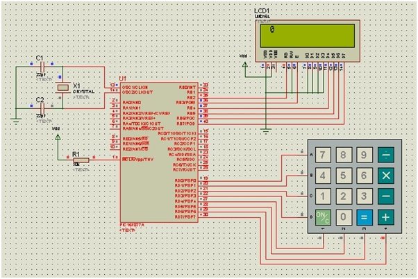
Keypads are available in various different sizes. The common sizes include 3×3, 3×4, and 4×4. In this project, we will interface a numeric keypad of 4×4 matrix with the PIC microcontroller 16F877A. The complete circuit diagram, designed on Proteus, is given below:
Circuit diagram of LCD interfacing with PIC microcontroller is given below:
Keypad Connections
Make all the connections as shown in the schematic diagram above. The keypad is connected to PORTD of the PIC microcontroller 16F877A. The four rows, labeled A, B, C, and D, are connected to the lower significant bits of the PORT (RD0-RD3), while the four columns, numbered 1, 2, 3, and 4, are connected to the most significant bits of the PORT (RD4-RD7). Connect the LCD module, crystal oscillator, and remaining components to the controller in a similar fashion as described in the previous article.
Video Demo
MikroC for Pic Keypad Interfacing Code
The code for this project is written in the MIKROC compiler and 8Mhz crystal is used in this project. If you do not know how to use MikroC for Pic, you can refer to these tutorials:
- How to Use “MikroC PRO for PIC” to Program PIC Microcontrollers
- Pic microcontroller programming in c using Mikroc Pro for PIC
Just like for LCD, MikroC also provides built-in library functions for a 4×4 Keypad. These library routines, however, can be used with other sizes of keypads as well. Functions, such as keypad_init, keypad_key_click, etc., simply need to be defined in the program, and the rest of the inner operations are performed by the MikroC compiler.
Write the following code in MikroC to interface a keypad with a PIC MCU:
/* KEYPAD INTERFACING WITH PIC16F877A */

int kpi;  // Variable to store the pressed key code

// Keypad module connections
char keypadPort at PORTD;
// End Keypad module connections

// LCD Module connections
sbit LCD_RS at RB1_bit;
sbit LCD_EN at RB0_bit;
sbit LCD_D7 at RB5_bit;
sbit LCD_D6 at RB4_bit;
sbit LCD_D5 at RB3_bit;
sbit LCD_D4 at RB2_bit;
// End LCD module connections

// LCD Pin direction
sbit LCD_RS_Direction at TRISB1_bit;
sbit LCD_EN_Direction at TRISB0_bit;
sbit LCD_D7_Direction at TRISB5_bit;
sbit LCD_D6_Direction at TRISB4_bit;
sbit LCD_D5_Direction at TRISB3_bit;
sbit LCD_D4_Direction at TRISB2_bit;
// End of LCD Pin direction

void main() {
    ANSELH = 0X00;  // Configure AN8-AN13 pins as digital I/O
    TRISB = 0X00;   // Set PORTB as output

    Lcd_Init();  // Initializing LCD
    Lcd_Cmd(_LCD_CLEAR);  // Clear Display
    Lcd_Cmd(_LCD_CURSOR_OFF);  // Cursor Off
    Lcd_Out(1, 1, "KEYPAD INTERFACE");  // Write "KEYPAD INTERFACE" in the first row
    delay_ms(500);  // 0.5s delay
    Lcd_Cmd(_LCD_CLEAR);  // Clear Display
    delay_ms(500);  // 0.5s delay
    Keypad_Init();  // Initializing Keypad
    Lcd_Out(1, 1, "PRESS A KEY");  // Write "PRESS A KEY" in the first row
    delay_ms(500);  // 0.5s delay
    Lcd_Cmd(_LCD_CLEAR);  // Clear Display

    do {
        kpi = 0;  // Reset key code variable

        // Wait for key to be pressed and released
        do
            kpi = Keypad_Key_Click();  // Store key code in kpi variable
        while (!kpi);

        switch (kpi) {
            case 1: kpi = 49; break;  // 7
            case 2: kpi = 50; break;  // 4
            case 3: kpi = 51; break;  // 1
            case 4: kpi = 65; break;  // Space
            case 5: kpi = 52; break;  // 8
            case 6: kpi = 53; break;  // 5
            case 7: kpi = 54; break;  // 2
            case 8: kpi = 66; break;  // 0
            case 9: kpi = 55; break;  // 9
            case 10: kpi = 56; break;  // 6
            case 11: kpi = 57; break;  // 3
            case 12: kpi = 67; break;  // =
            case 13: kpi = 42; break;  // /
            case 14: kpi = 48; break;  // x
            case 15: kpi = 35; break;  // -
            case 16: kpi = 68; break;  // +
        }

        Lcd_Chr(1, 2, kpi);  // Print key ASCII value on LCD
    } while (1);
}
How Does this Code Work?
This code is designed for interfacing a 4×4 matrix keypad with a PIC16F877A microcontroller and displaying the pressed keys on an LCD. The program begins by initializing the LCD and displaying a startup message. It then enters a continuous loop where it waits for a key to be pressed and released. Once a key is detected, the program maps the key to a corresponding ASCII value and displays it on the LCD. The keypad connections are established through the PORTD pins of the microcontroller, where rows (A, B, C, D) are connected to lower bits (RD0-RD3), and columns (1, 2, 3, 4) are connected to the higher bits (RD4-RD7). The LCD connections use specific pins on PORTB.
The code uses a switch-case structure to map the detected key to its ASCII equivalent. For example, if key 1 is pressed, it assigns the ASCII value 49 (the ASCII code for ‘1’) to the variable kpi. The program continually loops, waiting for subsequent key presses and updating the LCD display accordingly. This interaction creates a simple keypad interface where users can input characters, and the corresponding characters are promptly displayed on the connected LCD.
Applications
Keypads have been extensively used in automotive applications as well as in the food industry. Programmed keypads can be used in automated attendance systems at schools, offices, etc., where you enter your ID, which is displayed and simultaneously stored to mark your presence. Automatic door locks are usually accessed with a keypad control system in which a particular code is dialed on the keypad to open the door.
To download the circuit diagram and code for the above project, click on the following link: Code and circuit diagram
Keypad Library MikroC for Pic
The Keypad_Init function initializes the port for interaction with the keypad and doesn’t return any value. An illustration of its usage is provided with the line char keypadPort at PORTB; Keypad_Init();, where the keypadPort is configured to use the PORTB for keypad communication.
The Keypad_Key_Press function reads a key from the keypad when it is pressed. It returns the code of the pressed key, and if no key is currently pressed, it returns 0. An example use is demonstrated in the line char key; key = Keypad_Key_Press();, where the variable key is assigned the code of the pressed key, or 0 if no key is currently pressed.
Lastly, the Keypad_Key_Click function is a blocking call, meaning it waits until a key is both pressed and released. Upon key release, it returns the code of the pressed key, ranging from 1 to 16, depending on the specific key. If multiple keys are pressed simultaneously, the function waits until all keys are released and then returns the code of the first pressed key. If no key is clicked during the waiting period, it returns 0. An example usage is presented as char key; key = Keypad_Key_Click();, where the variable key is assigned the code of the clicked key or 0 if no key is clicked.
Conclusion
In this comprehensive tutorial, we have learned to interface a 4×4 matrix keypad with the PIC16F877A microcontroller. By integrating the keypad with the microcontroller’s GPIO pins and leveraging the MikroC for PIC and MPLAB XC8 compilers, we have crafted a robust interface that captures user input and presents it on an LCD display. The provided circuit diagram and code, along with the detailed explanations and application scenarios, equip readers with the knowledge and resources necessary to seamlessly incorporate keypad functionality into their projects.
You may also like to read:
- 7 Segment Display Interfacing with Pic Microcontroller
- SPI Communication with PIC microcontroller
- 16×2 LCD Interfacing with PIC Microcontroller – Examples
- UART Communication with Pic Microcontroller( Programming in MPLAB XC8 )
- PIC Microcontroller ADC – How to Use PIC18F4550 ADC
- Rotary Encoder Module interfacing with pic16f877a microcontroller
Hello
I tried your keypad code but it errors with Too many characters and Implicit conversion of Int to ptr at line 27.
Is there a solution?
I don’t know why are using facing such issue. This code is complied one and works perfectly.
need complete design of pure sin wave inverter
Hi i really need help on how to make door lock using 4*3 keypad, 2*16 lcd, solenoid lock and simpp pic.this pic is made by own prof. And i dont know the connectio and code can u suggest or help me please i really need to pass this project.please100x. This is my gmail anestojean0822@gmail.com.
Thank you
contact me at bilalmlaikuet@gmail.com with project details
Hi Mr. Malik,
I have a project for MicroControllers Course: converting users’s input decimal numbers to binary and as well, i must use Keypad and LCD and PIC16F877A . I am using MikroC Pro and your blog is very beneficial for me sure.Is it enough making this circuit for my project ?
Hi Malik,
I have a small project operating switch points at my model railroad using Arduino.
I use a keypad to generate funktions to each of my 32 switch points via I2C bus.
One, keypad(0X39), one 16x2LCD(0X3F), four PCF8575(0X38 – 0X35). Drivers for the point motors (solenoinds) is 8 of ULN2903. I have no problem communicating between the Keypad and LCD display.
Problem is to write the code for the slaves. How do I make the right slave to get the message, displayed on the LCD? I have tried with “1-8 should write to 0X35″, 9-16 should write to 0X36” and so on. No success!
There is two possibillities for the point motor, straight or curved.
I would like to use number + * for straight
I would like to use number + # for curve
Each point motor will use two outputs from ULN2803 one for each solenoid spool.
Please help ! How do I write it in the code?
Hello bilal this sight is awesome for people like me, you have explored so many things..as I am looking for a sight like this… in this programing when you entered any charecter..it will displayed it on the LCD right?..what about the 2nd char…where it will display.you didn’t mention for moving cursor right…? Or am I wrong
What is while(!kpi) means
Hi Bilal,
Thanks for another master piece. I benefit a lot from your articles on your site. I am still learning the ropes. After going through your code, Sir, I noticed with all due respect that some information provided by you are confusing, This I noticed could be as a result of the way the keypad was connected to the MCU.
I know you adjusted your code to get what you wanted and in that process, the desparity crept into the code.
Specifically I respectfully refer to these lines of your code:
Case 5 : kpI=53; //8
And some other lines are affected as well.
The ASCII for 5 is 53 as stated which is correct but your comment says it is key 8. I expected key 5. That left me confused.
I simulated the code on Proteus , I discovered that the pin assignment for PortD to the key is the issue.
The keypad Init() function of the keypad library does not specify how the pins are assigned to the pad and that could be he source of confusion.
Sir, here is the connection I used in Proteus to get what I wanted.:
PortD
D0. Row1 // input
D1. Row2 // input
D2. Row3 // input
D3. Row4 // input. Ignore for 4×3 keypad
D4 Col1 (A) // output
D5. Col2 (B) // output
D6. Col3 (C) // output
D7. Col4 (4) // output
Sir, with this configuration, surely, all information will conform.
May I use this opportunity to thank you for the numerous helpful tutorials you post on this site.
Sir, could you please post another article on keypad interfacing using this information to enable out learners like me learn the code without getting confused.
Thanks.
Yusuf.
While(1), always true
Hey Bilal! Can this project be pulled out using PIC16f1847?