7 Segment Display Interfacing with Pic Microcontroller: In the last tutorials, we have seen how to use MPLAB XC8 Compiler and How to interface an LED with pic microcontrollers such as PIC16F877A and PIC18F4550. 7 segment displays are also a type of LED display. To interface and control them with Pic microcontroller, we use GPIO pins as digital output pins. Because these displays consist of 7 light-emitting diodes connected in common anode or common cathode configuration.
Recommended Components
The following components are used in this project or are helpful for building it with a PIC microcontroller.
| Component | How it’s used in this project | Buy on Amazon |
|---|---|---|
| PIC16F877A microcontroller | Host MCU that drives the 7-segment display in this project. | Check Price |
| PICkit 5 programmer/debugger | Flashes the compiled firmware onto the PIC and debugs it. | Check Price |
| Single-digit 7-segment display (common cathode) | Single-digit display driven directly from the PIC I/O pins. | Check Price |
| Breadboard | Solderless base for wiring the PIC to the display. | Check Price |
| Jumper Wires | Connect the segment and common lines between parts. | Check Price |
As an Amazon Associate we earn from qualifying purchases. Prices and availability are accurate as of the date/time indicated and are subject to change.
How to Interface 7 segment Displays?
In this tutorial, we will start with an introduction of 7 segment displays? How to interface a 7-segment display with PIC microcontrollers. We will see examples with two compilers such as MPLAB XC8 compiler and MikroC Pro.
7 Segment Displays Introduction
Seven segment display is regarded as the most basic and simplest electronics display device. Simplest, because its working is easy to understand and its interface with the microcontroller is quite straight-forward.
Seven segments, as the name suggests, consist of seven LEDs organized in a specific pattern. Each LED is known as a segment and it is assigned a name from ‘a’ to ‘g’. Another additional 8th LED named ‘dp’ is also present sometimes in a 7-segment display which is used to illuminate a dot or a decimal point. As you can see from this diagram, it consists of 10 pins.
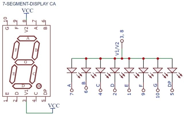
7 Segment Display Types
A common pin is also associated with the 7-segment, which is used to identify the type of 7-segment display; whether it is the common anode or a common cathode. In common anode display, the positive pins of all the LEDs are tied together to form the common pin which needs to be provided a ‘HIGH’ signal that means 5 volts signal. To turn on a specific segment, we connect that pin to the ground or logic low level.
In common cathode display, all the cathode connections of the LEDs are tied together which forms the common pin that needs to be grounded. To turn on a specific segment in common cathode mode, we connect that pin to the voltage or to a logic high level with a microcontroller
How to control 7 segment Display with Pic Microcontroller?
As we mentioned earlier, it consists of 7 light-emitting devices that are arranged in a rectangular design box. By controlling specific lights, we can display numbers from 0-9. Each segment is referred with the name from a to g. For example, if we want to display 1, we turn on segments ‘b’ and ‘c’ and to display 2, we turn on segments a, b, g, d, and e. Similarly we can display other numbers by controlling respective light-emitting devices.
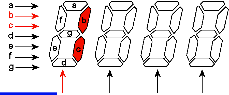
Note: If we use common anode type 7 segment display, control signals (a-g) will be active low (ground reference) and similarly for common cathode type, control signals are always active high level ( usually 5 volts).
In previous sections, we have seen that how to control 7 segments displays. As you know that we can easily interface 7 segment displays with a pic microcontroller by using GPIO pins of PIC microcontroller as digital output pins. It requires a simple interface similar to an LED interfacing tutorial.
7 Segment Display Interfacing with Pic Microcontroller in MPLAB XC8
In this section, we will see an example of 7 segment displays interfacing with pic microcontroller. We will use MPLAB XC8 compiler for programming.
Interfacing Circuit
This picture shows a connection diagram of 7 segment display with pic microcontroller. A common anode type display is used. Therefore, we connect a common terminal to the ground reference. This interfacing circuit used 330-ohm resistors for connection. These resistors are the current limiting resistors. Because of all GPIO pins of PIC18F4550 microcontroller can provide a maximum of 25mA current and also each segment LED needs only 10mA current to operate.
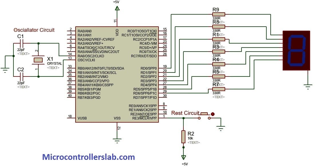
If we use a common anode type, the common terminal will be conned to 5 volts or Vcc.
7 segment Interfacing Code MPLAB XC8
If you are a beginner with MPLAB XC8 compiler, we recommend you to check this video. This video teaches how to create project in MPLAB XC8 compiler
To write code, first, we need to create a pattern that shows numbers by sending specific patterns to 7 segment display from PIC18F4450 microcontroller. For instance, in this interfacing, we used the PORTD of PIC18F4450 microcontroller. We send bit patterns to turn on and off specific segments according to the number that we want to display. We generated this table which contains bit patterns for all numbers from 0-9. This table shows 7 segment encoding for pic microcontroller programming.
| Number | A B C D E F G | PORTD (Hex) |
|---|---|---|
| 0 | 0 0 1 1 1 1 1 1 | 0x3F |
| 1 | 0 0 0 0 0 1 1 0 | 0x06 |
| 2 | 0 1 0 1 1 0 1 1 | 0x5B |
| 3 | 0 1 0 0 1 1 1 1 | 0x4F |
| 4 | 0 1 1 0 0 1 1 0 | 0x66 |
| 5 | 0 1 1 0 1 1 0 1 | 0x6D |
| 6 | 0 1 1 1 1 1 0 1 | 0x7D |
| 7 | 0 0 0 0 0 1 1 1 | 0x07 |
| 8 | 0 1 1 1 1 1 1 1 | 0x7F |
| 9 | 0 1 1 0 1 1 1 1 | 0x6F |
As shown in above table, we sends the hex value of the number to the PORTD of Pic microcontroller that we want to display. We will use only 7-bits of PORD to send data to segments from a-g.
This code displays numbers from 0-9 on 7 segment display with a delay one second.
#include <xc.h>
#include "config.h" // Configuration bits file stored in a header file
#define _XTAL_FREQ 20000000 //define crystal frequency to 20MHz

// This array stores binary bit pattern that will be send to PORTD
unsigned char binary_pattern[]={0x3F,0x06,0x5B,0x4F,0x66,0x6D,0x7D,0x07,0x7F,0x6F};

void main(void)
{
    TRISD = 0x00; //define PORTD as a output pin
    while(1)
    {
        //this loop sends all binary patterns to PORTD
        for (int i=0;i<10;i++)
        {
            PORTD = binary_pattern[i];
            __delay_ms(1000);  //add delay of one second
        }
    }
    return;
}
Simulation Single 7 Segment
Code Working
This program controls only one 7 segment display and the working of code is pretty straight forward.
- xc.h and config.h are the header files. xc.h header files contain a definition of internal registers of PIC18F4550 microcontroller.
- On the other hand, config.h header file contains configuration bits settings.
binary_pattern array consists of binary patterns of numbers for common cathode type seven segment display.
/ This array stores binary bit pattern that will be send to PORTD
unsigned char binary_pattern[]={0x3F,0x06,0x5B,0x4F,0x66,0x6D,0x7D,0x07,0x7F,0x6F};
After that, we set PORTD of PIC18F4550 microcontroller as a digital output by using direction control register TRISD.
TRISD = 0x00; //define PORTD as a output pinThis is the main part of the program that sends the value of binary_pattern array to PORTD after every one second. while(1) loop will keep executing indefinitely.
while(1)
    {
        //this loop sends all binary patterns to PORTD
        for (int i=0;i<10;i++)
        {
            PORTD = binary_pattern[i];
            __delay_ms(1000);  //add delay of one second
        }
    }
Multiplexing four 7 segment displays with PIC18F4550 in MPLAB XC8
Now you know how to interface a single 7-segment display with pic microcontroller. But in practical projects, we always need more than one display interfacing with pic microcontroller. For example, if we want to display ADC value, temperature, voltage, current measurement values on 7-segments, we need more than one display device. Therefore, we should also know how to design a 2-digit, 3-digit, and 4-digit display using seven-segments devices.
4-digit Seven-Segment Display Circuit PIC18F4550
This circuit diagram shows a connection between 4-digit 7-segment display and PIC18F4550 microcontroller.
As you can see from this circuit diagram, 4-digit display module has 12 pins. Six pins are used for each segment LED and we can use these common pins to drive all four digits. Pins 1-4 are control pins. Like pin1 controls the fourth digit. For example, when we want to display a number on the fourth seven-segment, we will make control pin1 active low incase of common cathode type and active high incase of common anode type display.
In this example, we use using 4-digital common cathode type display. Therefore, we will make these pins active low(ground reference) whenever we want to display something on specific seven-segment. This circuit provides these control signals from PORTB pins RB0, RB1, RB2, and RB2 for pin1,pin2, pin3, and pin4 respectively.
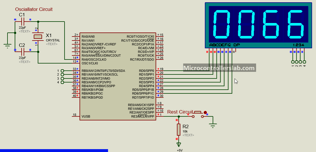
Similar to the last section, we use the PORTD of PIC18F4550 microcontroller to provide binary patterns according to the number that we want to display. Hence, connect PORTD pins RD0-RD6 with a-g pins of the 4-digital display.
4-digit Seven-Segment Display Programming
Programming four-digit 7-segment display is easy to understand if you know single device interfacing programming. First, create a new project by selecting the PIC18F4550 microcontroller and set configurations bits file using MPLAB XC8 compiler and save it in a header file. The first header file contains the definitions of PIC18F4450 registers and we stored configuration bits file in config.h header file.
#include <xc.h>
#include "config.h" // You must select 'HS' option from oscillator section
// this line define crystal frequency for built-in __delay_ms() functions
#define _XTAL_FREQ 20000000 //define crystal frequency to 20MHz
As we mentioned earlier, four pins (1-4) control the display of each seven-segment. These lines define the name of each control pin associated with PORTB pins RB0, RB1, RB2, and RB3. By defining names, we can use names inside the code instead of pin names. It makes the code easy to understand.
#define digit1 PORTBbits.RB0
#define digit2 PORTBbits.RB1
#define digit3 PORTBbits.RB2
#define digit4 PORTBbits.RB3
Here binary_pattern array consists of hex values of binary patterns according to the number that we want to display. An array is a data type just like int, float or char but it can hold a collection of similar data types. For instance, this line defines a character type array that consists of 10 characters type numbers.
// This array stores binary bit pattern that will be send to PORTD
char binary_pattern[]={0x3F,0x06,0x5B,0x4F,0x66,0x6D,0x7D,0x07,0x7F,0x6F};
As you know that in all programming languages, variables are used to store temporary or permanent data. In this example, these variables store temporary data. The variable counter stores data that we will display on the 4-digit seven-segment device. The variables a, b, c, and d are used to store first, second, third and fourth digit values.
unsigned int a,b,c,d;
unsigned int counter = 0;;
This section of the program defines the direction of GPIO pins of PIC18F4550 microcontroller. PORTD and PORTB pins are used as digital output pins. Therefore, we initialize them as digital output pins by setting PORTD and PORTB, direction control registers to active low i.e. TRISD=0x00 and TRISB =0.
Another interesting thing to note is that we declared digit control signals to active high. This is because we are using common cathode type seven-segment and it turns on with active low signals. Therefore, at the start, we initialize them as active high.
TRISD = 0x00; //define PORTD as a output pin
PORTD = 0X00;   // initialize PORTD pins to active low
TRISB = 0x00;
digit1 = 1;
digit2 = 1;
digit3 = 1;
digit4 = 1;
These lines extract digits for thousands, hundreds, 10th and unit place from counter value. In this example program, we display the counter value on 4-digit seven-segment. Inside the while loop, counter value increments after every iteration. These variables a, b, c, and c retrieve 1000’s, 100’s, 10th and unit digits data.
For example, after 1233 iterations, counter value will be 1234. After the execution of these instructions, the values of these variables will be a=1, b=2, c=3, and d=4;
    a = counter / 1000;   // holds 1000's digit
    b = ((counter/100)%10); // holds 100's digit
    c = ((counter/10)%10);  // holds 10th digit
    d = (counter%10);  // holds unit digiat value
This is the main part of the program that actually sends data to the seven-segment display. After calculating, digit values from the last step, this line sends data to each display unit. Due to common data lines, we can send data to one digit device at a time by turning on its control signal pin.
Now the question is what to do to display all 4-digits at a time? Don’t worry, microcontrollers operate at a very high frequency and we will update data to each display unit so fast that the human eye cannot detect this on/off time. We added a delay of 10ms before sending data to each seven-segment. The human eye cannot detect this 10ms difference.
PORTD=binary_pattern[a]; // send 1000's place data to fourth digit
digit1=0;   //  turn on forth display unit
__delay_ms(10);
digit1=1;   //  turn off forth display unit
PORTD=binary_pattern[b];  // send 100's place data to 3rd digit
digit2=0;    //  turn on 3rd display unit
__delay_ms(10);
digit2=1;  //  turn off 3rd display unit
PORTD=binary_pattern[c];  // send 10th place data to 2nd digit
digit3 = 0;  //  turn on 2nd display unit
__delay_ms(10);
 digit3 = 1;   //  turn off 2nd display unit
PORTD=binary_pattern[d];  // send unit place data to 1st digit
digit4 = 0;  //  turn on 1st display unit
__delay_ms(10);
digit4 = 1;  //  turn off 1st display unit
After displaying a 4-digit number, these lines check if the counter = 9999, if counter value reaches 9999, it will reset the counter value to zero and otherwise, increment its value by one.
if(counter>=9999) //wait till flag reaches 100
{
    counter=0; //only if flag is hundred "i" will be incremented
}
counter++; //increment flag for each flas
    }
Code Working and Simulation
As you can see from this proteus simulation, counter value is increasing one by one.
4-digit seven-segment Display Code MPLAB XC8
#include <xc.h>
#include "config.h"
#define _XTAL_FREQ 20000000 //define crystal frequency to 20MHz
#define digit1 PORTBbits.RB0
#define digit2 PORTBbits.RB1
#define digit3 PORTBbits.RB2
#define digit4 PORTBbits.RB3
// This array stores binary bit pattern that will be send to PORTD
unsigned char binary_pattern[]={0x3F,0x06,0x5B,0x4F,0x66,0x6D,0x7D,0x07,0x7F,0x6F};
unsigned int a,b,c,d;
unsigned int counter = 0;;
void main(void)
{
    TRISD = 0x00; //define PORTD as a output pin
    PORTD=0X00;   // initialize PORTD pins to active low
    TRISB=0X00;
    digit1 = 1;
    digit2 = 1;
    digit3 = 1;
    digit4 = 1;
    while(1)
    {

           a = counter / 1000;   // holds 1000's digit
           b = ((counter/100)%10); // holds 100's digit
           c = ((counter/10)%10);  // holds 10th digit
           d = (counter%10);  // holds unit digit value

PORTD=binary_pattern[a]; // send 1000's place data to fourth digit
digit1=0;   //  turn on forth display unit
__delay_ms(10);
digit1=1;   //  turn off forth display unit
PORTD=binary_pattern[b];  // send 100's place data to 3rd digit
digit2=0;    //  turn on 3rd display unit
__delay_ms(10);
digit2=1;  //  turn off 3rd display unit
PORTD=binary_pattern[c];  // send 10th place data to 2nd digit
digit3 = 0;  //  turn on 2nd display unit
__delay_ms(10);
 digit3 = 1;   //  turn off 2nd display unit
PORTD=binary_pattern[d];  // send unit place data to 1st digit
digit4 = 0;  //  turn on 1st display unit
__delay_ms(10);
digit4 = 1;  //  turn off 1st display unit

if(counter>=1000) //wait till flag reaches 100
{
    counter=0; //only if flag is hundred "i" will be incremented
}
counter++; //increment flag for each flas
    }
    return ;
}
Seven Segment Display Interfacing with Pic using MikroC Pro Compiler
This section discusses an example of seven-segment display interfacing with PIC16F877A microcontroller using MikroC for PIC compiler. Although the maximum part of code remains the same, the only difference is compiler setting and how to create a new project.
If you are a beginner in MikroC for PIC compiler, you can check this video lecture.
Multiplexing two 7 Segment display counter Example
In this section, we discuss an example of multiplexing two 7 segment displays with PIC16F877A microcontroller. We have used two 7-segment displays in this example to display a 0-99 counter. Let’s move forward by defining seven segment display. The code for this project is written using MikroC for pic.
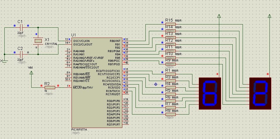
To display a counter of 0-99, two 7-segments of common anode type are interfaced with PIC16F877A in this project, one for tens and the other for ones. The seven pins of each segment are connected to the seven pins of PORTB and PORTC, starting from LSB, via a resistor of 560R. Each pin represents an alphabet which switches the corresponding LED bar on and off with respect to the code.
As per the connections shown in the circuit diagram, alphabet ‘a’ of the tens segment is connected to the RC0 pin of the MCU, ‘b’ is connected to RC1 pin and so on. The same pattern is followed for the one segment connected to PORTB. We have chosen both 7-segments with a common anode display. As such, the common pin of both 7-segments is connected to Vcc.
Multiplexing Seven Segment display code MikroC
Write the following code in the Code Editor Window of mikroC Compiler:
/* 7 Segment display counter 0-99 interfacing with PIC1F877A*/

void delay();
void main()
{
unsigned char i,j,ar[]={0xC0,0xF9,0xA4,0xB0,0x99,0x92,0x82,0xF8,0x80,0x90};
TRISB=TRISC=0x00;
do
{
for(i=0;i<10;i++)
{
PORTC=ar[i]; // for tens
for(j=0;j<10;j++)
{
PORTB=ar[j];    // for ones
delay();
}
}
}
while (1);
}

void delay() //delay routine
{
unsigned char i,j;
for(i=0;i<255;i++)
for(j=0;j<50;j++);
}
Code Working
A delay function has been declared at the beginning of the code which is used to slow done the abrupt changes in the counter of one segment, which is then effective for tens segment as well. Apart from char ‘i’ and ‘j’, an array ‘ar’ has also been declared. The values defined within the brackets correspond to digits from 0 to 9. But these are not the hex values of the actual digits 0-9.
These are the values that need to be generated on the port pins for the corresponding digit to appear on the 7-segment. For example, to display ‘5’ on the 7-segment, the LEDs that should be illuminated are ‘a’, ‘c’, ‘d’, ‘f’ and ‘g’. So, the port pins should give the output 0b10010010 to the 7-segment, which is equivalent in hex to 0x92.
The inner ‘for’ loop displays the ones counter and the outer ‘for’ loop is for the tens counter. The program is executed infinite times until aborted.
7 Segment Displays Applications
Seven segment displays are vastly used in our daily life equipment, be it the digital clocks at our homes or the electronic meters at our work stations. It can be used as a countdown or a timer when playing games or in competitions etc. The basic calculators also use a 7-segment display.
Compiler says that “#DEVICE is requires before this line.” What is missing?
which compiler you are using?
I’m using PIC C (C language). I tried to replay the fist statement to but still don’t work.
above code is written in Mikro c complier
Yes, I wrote that first. But its doesn’t work so I replace it of but still doesn’t work.
you must be having trouble while designing
SALLAM, PLS I NEED YOUR HELP I AM A COMPUTER SCIENCE STUDENT AND NEED ELECTRICAL PROJECT RELATED TO COMPUTER, OR ANY ELECTRICAL BASE PROJECT THAT AS TO DO WITH PROGRAMMING( PLS WITH THE COMPLETE CODE) THANKS
what does it mean ar[]={0xC0,0xF9,0xA4,0xB0,0x99,0x92,0x82,0xF8,0x80,0x90} ?
tnks
Sir thanks for the great project sir actually i want to show this temperature result also on 16*2 display on the same time. Sir as you see that the port d is not used in this schematic diagram so please tell ,me how can i show the same temperature on both display and 7 segment on the same time.
sorry I write temperature actually its digitts
Can I use pic16F84A for this project?
finding it so hard working with it
share your difficulties
Please how can i scroll text on seven segment.
Pls i need to design a counter from 0-46 using two seven segment display and push button in assembly language
Pls i need this code in assembly language
Hello billal..how does the delay function works in for loop..how yo get the vale 255 and 50 in the for loop for delay…
hi bilal, i need to design a counter from 1-30 using two seven segment display using push button.i’m using PIC16F877A with Hi-Tech Compiler
Nice tutorial for beginners. Can save more pin on microcontroller by multiplexing.
in our area we use 240,50hz. please may u help me with a code so i can edit it or just a clue or even the code in text so i can do that. thanks much
I want Code for Dual 7 segment dispaly from 0-99
The “ABCDEFG” in the number table should be arranged in reverse order “GFEDCBA”.
How can I use 4 pins from PORTB and PORTC for the interfacing of seven segment display