Recommended Components
The following components are used in this project or are helpful for building it with a PIC microcontroller.
| Component | How it’s used in this project | Buy on Amazon |
|---|---|---|
| PIC16F877A microcontroller | Host MCU that sends and receives data over its hardware UART. | Check Price |
| PICkit 5 programmer/debugger | Flashes the compiled hex file onto the PIC and debugs it. | Check Price |
| FTDI / USB-TTL serial adapter | Bridges the PIC UART to your PC to send and monitor serial data. | Check Price |
| Breadboard | Solderless base for wiring the PIC and components together. | Check Price |
| Jumper Wires | Connect power, ground and signal lines between the parts. | Check Price |
As an Amazon Associate we earn from qualifying purchases. Prices and availability are accurate as of the date/time indicated and are subject to change.
Why we need UART Communication?
As you know that all modern microprocessors and microcontrollers transfer data to other digital devices in bytes. Two modes of communication are used to transfer data. One is parallel and the other one is a serial method. Parallel mode is used when high-speed transmission needed, and distance is short between the sender and receiver. On the contrary, Serial communication is used for long-range data communication and when less number of connecting wires (GPIO pins) are available. For example, in the case of microcontrollers, general-purpose input-output ports are usually less. Therefore, Microcontrollers use serial communication to transmit and receive data from other devices.UART Communication Brief Description
UART communication is of two types such as synchronous and asynchronous. Asynchronous is the most widely adopted method in microcontrollers and peripherals that used to transfer data serially. In the asynchronous protocol, the 8-bit data(byte) packet is embedded within a start and stop bit. This is also known as a UART data frame. Sometimes one extra parity bit is also used before the end bit. Parity bit checks if data changes during transmission or not.UART Data Transmission Process

- Normally when no data transmission occurs, UART lines remain active high.
- When the transmitting microcontroller wants to transmit data, it makes the serial line low for one clock cycle.
- After that receiving device detects this signal transition and starts to read the data frame.
- The speed of data reception depends on the baud rate.
- After that transmitting microcontroller sends a low to high signal for at least two clock cycles to signal the end of the data frame.
PIC Microcontroller UART Module
PIC18F4550 microcontroller has one USART module. Synchronous Asynchronous Receiver Transmitter (USART) module can be configured either in Full-Duplex or half-duplex mode. In full-duplex mode, data transfer simultaneously in both ways (transmit and receive). On the contrary, in half-duplex mode, data transfer only in one direction at a time. Peripherals such as ADCs, serial EEPROM, D/A converters need only half-duplex mode. PIC microcontrollers support both modes.UART Pins PIC18F4550
UART pins of this pic microcontroller chip are available on PORTC pins such as RC6/TX and RC7/RX. That means RC6 is a transmit pin and RC7 is used to receiving data. Before using these pins for serial communication, we should set direction control registers of these pins to logic high.TRISCbits.RC7 =1 // bit must be set (= 1) TRISCbits.RC6 = 1 // bit must be set (= 1)Although the receiver pin should be set as digital input and transmitter pin as an output. But the UART module will set these pins input to output automatically according to requirement.
PIC18F4550 UART Module Configuration Registers
Now let’s start with Internal configuration registers and how to use these register to configure the UART communication module of PIC18F4550 microcontroller. There are three main control registers associated with the PIC18F4550 microcontroller UART module:- Transmit Status and Control (TXSTA)
- Receive Status and Control (RCSTA)
- Baud Rate Control (BACON)
Data Registers
Other than control registers, four other registers are used for data storage, data transmission and for Baud rate generation. Like control registers, Data registers are also of 8-bit size.- TXREG USART Transmit Register: It holds the data that the transmitter device wants to send to a receiver device.
- RCREG EUSART Receive Register: It stores data that PIC18F4550 microcontroller on RC7 pin.
- SPBRGH and SPBRG: These 8-bit registers are used to calculate the baud rate.
UART Transmit Status and Control (TXSTA)
This is an 8-bit register that is used to control and enable transmission features. Firstly, it selects data transfer type either synchronous or asynchronous. Secondly, it chooses the data frame size ( 8-bit or 9-bit).
Bit7 CSRC – Clock Source Select Bit
This bit selects the clock source input for the UART module. PIC18F4550 supports both synchronous and asynchronous modes of communication. Asynchronous serial communication does not require a clock source. Therefore, this bit acts as a don’t care, if you are using asynchronous mode. In this tutorial, we will be using asynchronous mode. Therefore, it will be a don’t care.On the other hand, if the synchronous mode is selected, we should configure CSRC according to the master and slave mode.- Set CSRC= 1, if you want to use Master mode and clock generated internally from the baud rate generator
- Set CSRC= 0, if slave mode selected and the clock will be used from an external source
Bit6 TX9 – Data width Selection
TX9 selects data format width either 9-bit transmission or 8-bit transmission.TXSTAbits.TX9=1 // selects 9-bit data transmission format TXSTAbits.TX9=0 // selects 8-bit data transmission format
Bit5 TXEN – Transmission Enable
It used to enable and disable transmit data from UART pin RC6/TX.TXSTAbits.TXEN = 1 //Transmit enabled TXSTAbits.TXEN = 0 // Transmit disabled
Bit4 SYNC (Communication Mode Select)
This bit selects the synchronous and asynchronous mode. Setting SYNC to one selects synchronous and other asynchronous.Bit3 SENDB ( Send Break Character)
It sends a signal to show that transmission is completed.Bit2 BRGH ( High Baud Rate Selector )
This is a high baud rate select bit. By default, a low-speed mode is selected. If we want to use high speed, then we can set BRGH =1 to get a high baud rate. By setting BRDG, we can double the baud rate with the same operating frequency of a microcontroller.Bit1 TRMT ( Transmit Register Status )
It is a flag bit that shows the status of transmitting shift register ( TXREG ).- If TRMT= 0, that means data transmission is in process and TXREG still holds data.
- Otherwise, if TRMT=1, that means microcontroller completed data transfer and TXREG is empty.
Bit0 TX9D ( 9th Bit of Data Frame)
This is a readable bit. We can address it either as a 9th bit of data or a parity bit.PIC UART RCSTA: Receive Status and Control Register
RCSTA is an 8-bit register used to program the UART receiver module of PIC18F4550 microcontroller. Besides other functions, it enables/ disables the UART pins to receive data on the RX pin.- SPEN Bit7
RCSTAbits.SPEN = 1 // enables the serial communications pins
RCSTAbits.SPEN = 0 // disables serial communication port and remains in reset mode.
- RX9 Bit6
RCSTAbits.RX9 = 1 // 9-bit reception
RCSTAbits.RX9 = 0 // 8-bit reception
- SREN Bit5
- CREN Bit4
RCSTAbits.CREN = 1 // It enables receive register to continously receive data
RCSTAbits.CREN = 0 // Otherwise disable
- ADDEN Bit3
- FERR Bit2 Framing Error Bit
RCSTAbits.FERR = 1 // Framing error
RCSTAbits.FERR = 0 // No Framing error
- OERR Bit1 Overrun Error Bit
RCSTAbits.OERR = 1 // Overrun Error
RCSTAbits.OERR = 0 // No Overrun Error
- RX9D Bit0
How to Calculate Baud Rate of PIC8F4550 UART?
What is Baud Rate?
Baud rate defines the rate of data transfer between two devices such as transmitting and receiving microcontrollers. It is also known as bits per second. This data transfer rate depends on the type of microcontroller or device we are using. Some old computers support the transfer rates between 100 to 9600 bps. However, modern microprocessors and microcontrollers support up to 56k.This table shows some of the most widely used baud rates for PIC18 microcontrollers that are used to transfer data between the microcontroller and personal computers.| Number | Baud rate |
|---|---|
| 1 | 1200 |
| 2 | 2400 |
| 3 | 4800 |
| 4 | 9600 |
| 5 | 19200 |
| 6 | 38400 |
| 7 | 57600 |
PIC18F4550 Microcontroller Baud Rate Registers
But in the case of pic microcontrollers, the baud rate is programmable. For PIC18F4550 microcontroller, we can set the desired baud rate with this formula:Desired Baud Rate = FOSC/(64 ([SPBRGH:SPBRG] + 1))Where:
- FOSC is an operating frequency of PIC18F4550 microcontroller
- SPBRGH: SPBRG: We should upload values of the nearest integer to these two registers according to the desired baud rate.
SPBRGH: SPBRG =( FOSC / 64 x Baud_Rate ) - 1For example, we want to set the baud rate of 9600 and FOSC is 20MHz. Hence:
SPBRGH: SPBRG = ( 20 MHz / 64 x 9600) - 1
SPBRGH: SPBRG = ( 20 MHz / 614400) - 1 = 31.55=32
Hence SPBRG=0 and SPCRG=32.Note: This calculation is based on BRGH =0 of the TXSTA register. Because we didn’t enable high-speed data transfer options. But if you enable BRGH =1, this formula will become:
SPBRGH: SPBRG =( FOSC / 16 x Baud_Rate ) - 1
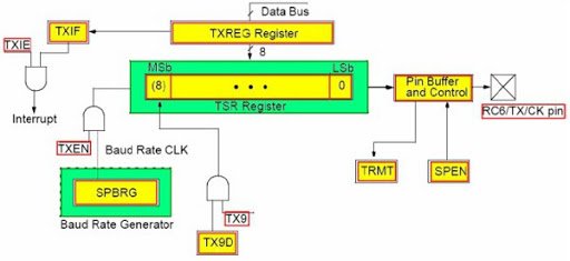
PIC18F4550 UART Programming to Send Data Serially
In this section, we will see how to send data serially using UART transmit pin of PIC18F4550 microcontroller. Follow these steps to program to send data serially:- First place the data ( byte) inside a transmit register (TXREG) of UART. We can send a maximum of one character at a time. Because UART transmits register is of 8-bit size and UART serial communication supports maximum 9-bit of a data frame.
- TXREG is a transmit shift register whose function is to get data from the microcontroller and send it to TX pin serially bit by bit.
- After that enable TXEN and initialize baud rate.
- When it completes sending data serially, the TRMT flag becomes high that indicates that transmission is completed.
PIC UART Transmitter Code
This example code transmits data serially to any UART based device at the baud rate of 9600. Before using this code, you should include a configuration file for the PIC18F4550 microcontroller. You can generate a configuration file using the MPLAB XC8 compiler.#include <xc.h> // Includes header file for PIC Microcontroller
#include "pic18f4550_config.h" // Include configuration file
#define F_CPU 8000000/64 // value to calculate baud rate
// This function used to generate delay in miliseconds
void MSdelay(unsigned int val)
{
unsigned int i,j;
for(i=0;i<=val;i++)
for(j=0;j<81;j++);
}
//This function initialize UART module
void UART_Initial(long baud_rate)
{
float bps;
TRISCbits.RC6=1;
TRISCbits.RC7=1;
bps = (( (float) (F_CPU) / (float) baud_rate) - 1); // sets baud rate
SPBRG=(int)bps; // store value for 9600 baud rate
TXSTAbits.CSRC = 0; // Don't care for asynchronous mode
TXSTAbits.TX9 = 0; // Selects 8-bit data transmission
TXSTAbits.TXEN = 1; // Enable Data tranmission on RC6 pin
TXSTAbits.SYNC = 0; // Selects Asynchronous Serial Communication Mode
TXSTAbits.BRGH = 0; // Default Baud rate speed
BAUDCONbits.BRG16 = 0; // selects only 8 bit register for baud rate
RCSTA = 0x90; // Enables UART Communication PORT
}
void UART_Write( char data )
{
//while (TXIF == 0);
TXREG = data;
while(TRMT==0); // wait until transmit register not empty
}
void main(void)
{
OSCCON=0x72; // Select internal oscillator with frequency = 8MHz
UART_Initial(9600);
while(1)
{
UART_Write('U'); // Send character U
UART_Write('A'); // Send character A
UART_Write('R'); // Send character R
UART_Write('T'); // Send character T
UART_Write('\r'); // Send carriage return for new line
MSdelay(1000); // adds delay of one second
}
return;
}This code sends UART on transmit TX pin after every one second. For demonstration purposes, we have used a virtual terminal in proteus. The virtual terminal used emulate hyper terminal to send and receive data serially. As you see this simulation, terminal receives ‘uart’ text after every one second.- To simulate this in proteus, copy the above code and generate configuration bits with MPLAB XC8 compiler and add as a header file.
- After that generate Hex code, upload in proteus and click on play button. You will see this result in virtual terminal.
PIC18F4550 UART Programming to Receive Data Serially
In this section, we will see how to receive data on the UART pin (RC7/RX) of the PIC18F4550 microcontroller. The code for the receiver part is almost the same as the transmitter part expect this UART_READ() function.char USART_Read()
{
while(RCIF==0); // see if data on RC7 pin is available
if(RCSTAbits.OERR)
{
CREN = 0;
NOP();
CREN=1;
}
return(RCREG); //read the byte from recieve register and return value
}This line first checks if data is available to read. If not, it will keep waiting and hold there.while(RCIF==0); // see if data on RC7 pin is availableIf available, OERR checks, if there is any overrun error in the data. After that, it receives data from RCREG and returns through a function call.
PIC UART Data Receiving Program
In this example code, we will turn on LED based on the data received on serial receive pin of PIC18F4550 microcontroller.#include <xc.h>
#include <stdio.h>
#include <string.h>
#include <stdlib.h>
#include "pic18f4550_config.h" // Include configuration file
#define F_CPU 8000000/64 // value to calculate baud rate
void MSdelay(unsigned int val)
{
unsigned int i,j;
for(i=0;i<=val;i++)
for(j=0;j<81;j++);
}
void UART_Initial(long baud_rate)
{
float bps;
TRISCbits.RC6=1;
TRISCbits.RC7=1;
bps = (( (float) (F_CPU) / (float) baud_rate) - 1); // sets baud rate
SPBRG=(int)bps; // store value for 9600 baud rate
TXSTAbits.CSRC = 0; // Don't care for asynchronous mode
TXSTAbits.TX9 = 0; // Selects 8-bit data transmission
TXSTAbits.TXEN = 1; // Enable Data tranmission on RC6 pin
TXSTAbits.SYNC = 0; // Selects Asynchronous Serial Communication Mode
TXSTAbits.BRGH = 0; // Default Baud rate speed
BAUDCONbits.BRG16 = 0; // selects only 8 bit register for baud rate
RCSTA = 0x90; // Enables UART Communication PORT
}
char USART_Read()
{
while(RCIF==0); // see if data on RC7 pin is available
if(RCSTAbits.OERR)
{
CREN = 0;
NOP();
CREN=1;
}
return(RCREG); //read the byte from recieve register and return value
}
void main(void)
{
char data;
OSCCON=0x72; // Select internal oscillator with frequency = 8MHz
TRISDbits.RD0=0; //Make RD0 pin as a output pin
PORTDbits.RD0=0; //initialize RD0 pin to logic zeeo
UART_Initial(9600);
while(1)
{
data=USART_Read();
if(data=='A')
PORTDbits.RD0=1;
else
PORTDbits.RD0=0;
}
return;
}We connect an LED with an RD0 pin of PORTD. We define this pin as a digital output pin. If data received on the RC7/RX pin is character ‘A’, LED will turn on. Otherwise LED remains off whatever data receives serially. You can read this tutorial on How to use GPIO pins of PIC Microcontrollers if you don’t know how to interface a Light-emitting diode with a pic microcontroller.
Code Working
In this code, the only new part is the data receiving and LED controlling part. The rest of the code is same. I have already explained UART_Read function above.data=USART_Read(); if(data=='A') PORTDbits.RD0=1; else PORTDbits.RD0=0;
- In this code, this line ‘data=USART_Read();’ receives data and store it inside a character type variable ‘data’.
- If condition checks if received character is equal to A.
- After evaluating this condition, if the answer is true, the RD0 pin will become high and turns on the LED.
- Otherwise LED will remain off.
Summary
In this tutorial, we have learned the following concepts of PIC Microcontroller UART:- Control and Data Registers Configuration
- How to send a string with pic UART
- How to use receive string with pic UART
Everything is very open with a precise explanation of the issues.
It was truly informative. Your site is very helpful. Many thanks for sharing!
I visit daily a few sites and sites to read articles, except this
weblog offers quality based articles.
Sir,
Iam using a controller with a display. Iam getting in display only as cccccccccccccccccccccccccccccccc.
My PCB contains ADC, USART, and others. Can u pls tell me why Iam getting only c alphabet in display