This tutorial will focus on the 4×4 keypad and its interfacing and programming with Arduino. We will see how to wire the keypad with an Arduino board and write the program for communication between Arduino and keypad. I recommend you to check this first tutorial on getting started with Arduino Uno R3. In embedded devices, one of the essential parts is a keypad and it is used to interact with embedded devices. A keypad is an input device that is used to give commands to other devices, from calculators to computers; input is given through the keypad.
Recommended Components
The following components are used in this project or are helpful for building it with the Arduino.
| Component | How it’s used in this project | Buy on Amazon |
|---|---|---|
| Arduino Uno R3 | The main controller board that runs the sketch and drives all the components in this project. | Check Price |
| Membrane keypad | The 4×4 matrix keypad whose key presses the Arduino scans and decodes. | Check Price |
| Breadboard | Lets you build and prototype the circuit without soldering. | Check Price |
| Jumper Wires | Used to make all the connections between the Arduino and the components. | Check Price |
As an Amazon Associate we earn from qualifying purchases. Prices and availability are accurate as of the date/time indicated and are subject to change.
Introducing Keypads
Keypads consist of push buttons arranged in row and column patterns. That means if we take an example of a 4×4 keypad, it will internally consist of 16 push buttons. To save microcontroller pins, keypads are arranged in the form matrix of rows and columns. For instance, a 4×4 keypad is arranged into a matrix of four rows and four columns. By using this pattern, we will need only 8 GPIO pins of Arduino.
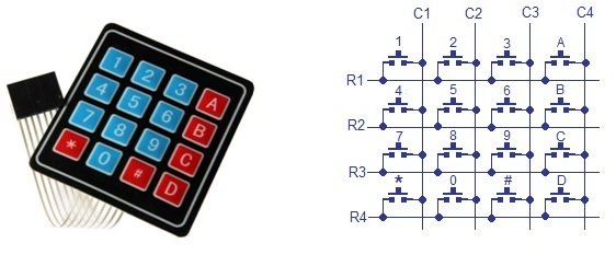
The status of each key/switch is determined by Scanning the rows or columns. The column pins (Col 1–Col4) are connected to the microcontroller as the inputs pins and the rows pins (Row 1–Row 4) are connected to the output pins of the microcontroller. Normally, all the column pins are pulled high by internal or external pull up resistors. Now we can read the status of each switch through scanning.
How to Read Data from Keypad with Arduino GPIO Pins?
Scanning is done in a different way. Columns pins are used as input pins, and rows pins are used as output.
For finding Column number
- When a switch/key is pressed, the corresponding row and column will get short.
- Output of the corresponding column goes to go low.
- Since we have made all the rows zero so this gives the column number of the pressed key.
For Finding Row number
- After the detection of column number, the controller set’s all the rows to high.
- Each row is one by one set to zero by the microcontroller and the earlier detected column is checked and obviously it becomes zero.
- The row due to which the column gets zero is the row number of the pressed key.
The following figure shows the pinout of a 4×4 keypad.
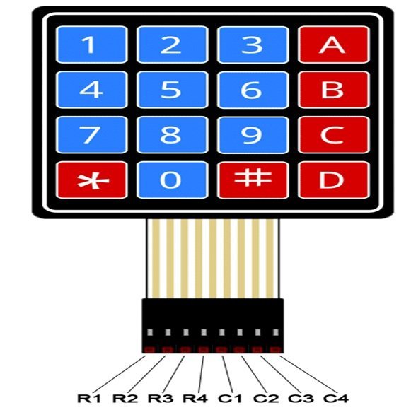
The output connector provides output pins for rows and columns. The first four pins from the left are rows and the last four pins from the right are the columns. To sense the state of each pushbutton from a specific location of a row and a column, we will use digital pins of Arduino.
Keypad internal diagram
As discussed earlier, internally a 4×4 keypad consists of a matrix of 4×4 push buttons. When a particular push button is pressed, a particular row and column make contact with each other. In other words, pressing a push button makes connection of one of the row lines with one of the column lines. It allows the current to pass between this row and column. This contact or current flow will be used to detect which particular key is pressed.
Identifying the Pins of 4×3 Keypad
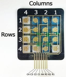
First you need to get a piece of paper and draw the right hand diagram as you see it below. I’ve already written my pin numbers (1, 2, 3 across the bottom and 7, 6, 5, 4 down the right side) which you can just leave off of your drawing. Next, you are going to use your Ohm meter to find out which pins are connected to which keys. The first thing to do is count how many pins are on your keypad (as seen in the photo below.) The photo is showing 14 pins though not all of the pins are used. Don’t worry, once you’ve completed this procedure you will know which pins are unused and can be ignored.
Note: If you bought an original keypad used for this purpose then you don’t need to figure out pins but if you got it from some other electronic device then you need to identify pins which will be used for this purpose.
Procedure
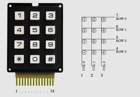
- Connect your Ohm meter leads to pins 1 and 2.
- Press all the buttons until the meter indicates a closure.
- Write down the pin numbers next to the column and row for the key you just found. Example: Your meter is connected to pins 1 and 5. When you pressed the number 7 your meter reacted. Write 1 under COL0 and 5 next to ROW2.
- If the meter didn’t react then move the meter lead from pin 2 to pin 3 and repeat steps 2 and 3 above.
- Now, keep moving the lead to the next pin and repeat steps 2 and 3 for each pin.
- Once you have reached the end move the first meter lead from pin 1 to pin 2 and repeat steps 2 and 3 while connecting the second meter lead to pins 3 through the highest pin.
- Once you have completely identified all the pins on the diagram then you can safely ignore any unused keypad pins. You are now ready to wire the keypad to your Arduino.
If you bought keypad look one below. You don’t need to perform above steps. Below diagram is enough for knowing pin configuration.

Interfacing 4×4 Keypad with Arduino
Now after learning about the keypad let us connect it with Arduino. We will require the following components.

Required Components
- 4×4 keypad
- Arduino UNO
- Connecting Wires
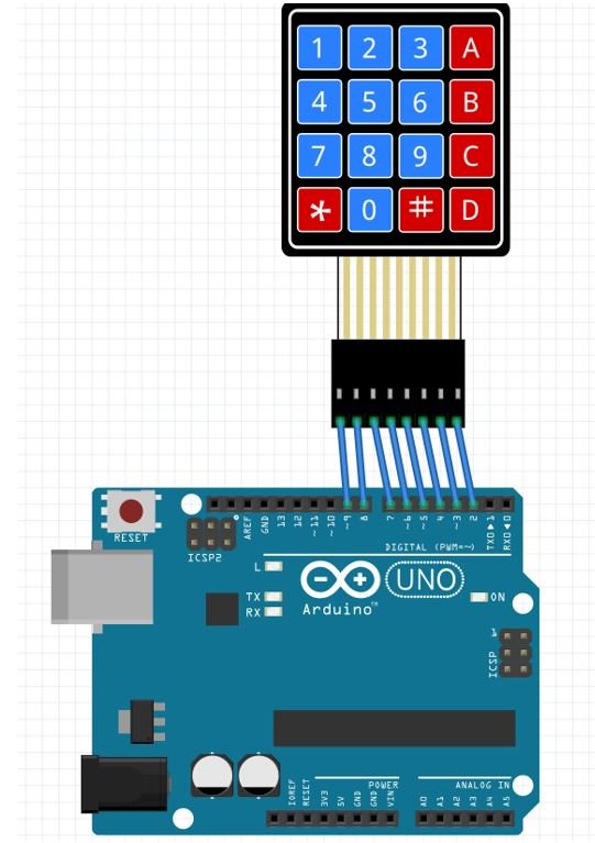
These are the Arduino pins that we will use (starting from left):
| Keypad | Arduino |
| pin 1 (R1) | Pin 9 |
| pin 2 (R2) | Pin 8 |
| pin 3 (R3) | Pin 7 |
| pin 4 (R4) | Pin 6 |
| pin 5 (C1) | Pin 5 |
| pin 6 (C2) | Pin 4 |
| pin 7 (C3) | Pin 3 |
| pin 8 (C4) | Pin 2 |
We will use Arduino IDE to program our Arduino board.
Install Keypad Library
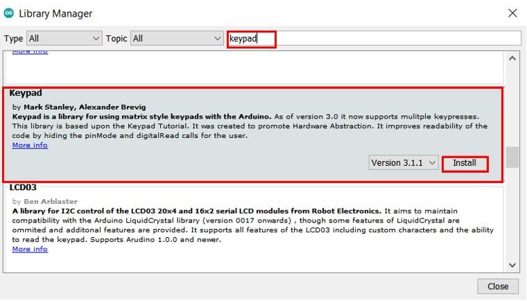
We will use the Keypad library by Mark Stanley and Alexander Brevig. This library will make it easy to work with the 4×4 keypad.
We will use the Library Manager in our Arduino IDE to install the latest version of the library. Open your Arduino IDE and go to Sketch > Include Libraries > Manage Libraries. Type ‘keypad’ in the search bar and install the latest version.
Arduino Keypad Sketch
Open your Arduino IDE and go to File > New to open a new file. Copy the code given below in that file and save it.
#include <Keypad.h>

const byte ROWS = 4; //four rows
const byte COLS = 4; //four columns

char keys[ROWS][COLS] = {
    {'1', '2', '3', 'A'},
    {'4', '5', '6', 'B' },
    {'7', '8', '9', 'C'},
    {'*', '0', '#', 'D'}
};

byte rowPins[ROWS] = {9,8,7,6}; //connect to the row pinouts of the keypad
byte colPins[COLS] = {5,4,3,2}; //connect to the column pinouts of the keypad

Keypad keypad = Keypad( makeKeymap(keys), rowPins, colPins, ROWS, COLS );

void setup() {
    Serial.begin(9600);
}

void loop() {
    char key = keypad.getKey();
    if (key != NO_KEY) {
        Serial.println(key);
  }
}
How does the Code Work?
We will start by including the Keypad.h library.
#include <Keypad.h>The following lines of code are for the keypad keys defining the rows, columns, and the array matrix for the keys.
If using a 4×3 keypad then set the ROWS variable to 4 and COLS variable to 3.
const byte ROWS = 4; //four rows
const byte COLS = 4; //four columns

char keys[ROWS][COLS] = {
    {'1', '2', '3', 'A'},
    {'4', '5', '6', 'B' },
    {'7', '8', '9', 'C'},
    {'*', '0', '#', 'D'}
};
Specify the Arduino pins connected with the row and column pins of the keypad as shown below:
byte rowPins[ROWS] = {9,8,7,6}; //connect to the row pinouts of the keypad
byte colPins[COLS] = {5,4,3,2}; //connect to the column pinouts of the keypad
Moreover, we will create an object of Keypad library called ‘keypad.’ It takes in five parameters. The first is makeKeymap(keys) which is used to initialize the internal keymap as that set by the user. The second parameter is rowPins that indicates the Arduino pins connected to the row pins of the keypad. Likewise, the third parameter is colPins that indicates the Arduino pins connected to the column pins of the keypad. Lastly, the fourth and fifth parameters are ROWS and COLS that set the number of rows and columns present in the keypad respectively.
Keypad keypad = Keypad( makeKeymap(keys), rowPins, colPins, ROWS, COLS );Inside the setup() function, open the serial monitor at a baud rate of 9600.
void setup() {
    Serial.begin(9600);
}
Inside the loop() function, we will print the key pressed in the serial monitor using the getKey() method.
void loop() {
    char key = keypad.getKey();
    if (key != NO_KEY) {
        Serial.println(key);
  }
}
Testing the Circuit
- After hardware connection, insert the sample sketch into the Arduino IDE.
- Using a USB cable, connect the ports from the Arduino to the computer.
- Upload the program.
- See the results in the serial monitor
- Now whichever key you press, it is shown on serial monitor of Arduino IDE.
Watch the video demonstration below:
You may also like to read:
- 16×2 LCD Interfacing with Arduino – Explained with Example Codes
- Measure Analog voltage using Arduino ADC
- Interface HC-SR501 PIR Sensor with Arduino
- Interface DS1307 RTC Module with Arduino – Display Date/Time on OLED
- Infrared Sensor Module Interfacing with Arduino – Obstacle Detection
- Joystick Based Servo Motor Control using Arduino
- Servo Motor Control and Interfacing with Arduino
- DS18B20 Temperature Module interfacing with arduino
What’s up, I wish for to subscribe for this
website to obtain newest updates, therefore
where can i do it please help out.
Hi,
Easier to connect via I2C and PCF8574 to the Arduino.
You can also connect Display 16×2 with the same type PCF8574 to I2C BUS and it will only take up 2 I/O on the Arduino!
Hi Max, Yes you are right. But this tutorial is just to give an idea to beginners about keypad interfacing with Arduino. There are many ways to save GPIO pins of Arduino. Even with one Analog pin Arduino we can scan a keypad of any size.