In this tutorial, we will perform UART or serial communication between two Arduino boards using UART software library of Arduino IDE. To debug and program Arduino using a USB port, the serial port which is known as Universal Asynchronous Receiver/Transmitter (UART) Communication is used. For most sensors and systems, the main communication method is considered to be UART. In order to share workload, information and perform different tasks; sometimes communication between to Arduino is necessary.
Communication between two Arduino boards using Software Serial
We will use a serial software library which is available in Arduino IDE. But the questions why we want to use the software UART library of Arduino when Arduino Uno has one UART port available on D0 and D1 pins. Because, Arduino only have one UART port and sometimes in embedded projects, we require more than one UART communication port to interface different sensors and modules such as GSM, GPS, Bluetooth, Xbee, etc.
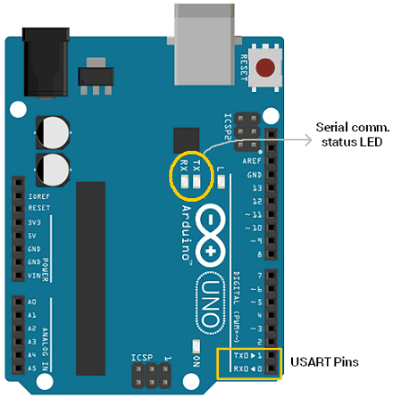
The other important reason to use the uart software library is that the UART port of Arduino is used by the onboard USB connection. This USB connection transfers data to the Arduino IDE serial monitor using Rx and Tx pins.

Although Arduino Mega has up to four serial communication ports. But, maximum Ardiuno compatible boards do not have multiple serial ports. In this case, a specially implemented software library is used to simulate UART communication behavior on other digital input output pins of Arduino. It is very easy to simulate serial UART communication but it should be remembered that it does not have any dedicated hardware and it will utilize the resources of already given Arduino Board like memory and execution time. However, all the functions which are usually available in hardware serial ports can be simulated and utilized using software serial ports.
Arduino SoftwareSerial Library
Arduino IDE has a built-in software serial library which allows use to perform serial communication using other digital input-output pins. By using SoftwareSerial library, we can communicate with multiple devices or sensors over the UART interface.
To use this library, first include the header file of software serial library using this line:
#include <SoftwareSerial.h>After that create an instant or object of the software serial library with a name of your own choice. For example, this line creates an object with the name of UART0. As an argument, we pass the name of digital pins which we want to use for serial communication. First argument is a receiver pin(RX) and the second argument is a transmit pin (TX). Hence, this line sets pin2 as a Rx pin and pin3 as a Tx pin for UART0.
SoftwareSerial UART0(2, 3); // RX, TXConnection Diagram Between Two Arduino Boards via Serial Pins
Following figure shows a connection diagram between two Arduino boards using digital pins to simulate a UART communication port using a pre-built library.
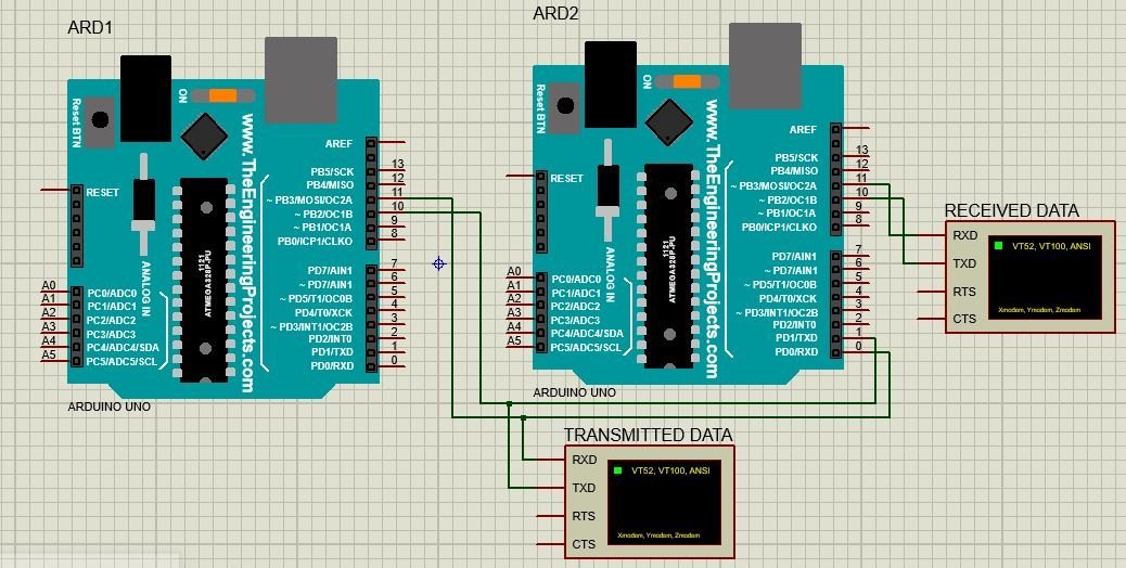
Consider we are using digital pin 11 and pin 10 as Tx and Rx for both Arduino boards.
- Connect virtual pin Tx of first Arduino board with pin Rx of second Arduino board.
- Connect virtual pin Rx of first Arduino board with pin Tx of second Arduino board.
- Virtual Tx pin of Arduino 1 transmit data to real buffer of receiver Arduino 2 and this data is written on virtual Tx pin of receiver Arduino 2 which is than shown on virtual terminal named as “Received Data”
- In order to monitor the status of transmitter and receiver Arduino, virtual terminals have been used.
- Connect the GND pin of both Arduino board together (if using real Arduino Boards)
- In case both Arduinos are not powered up using USB port than it is necessary to connect 5V pins of both Arduinos and power up one Arduino with USB port. (if using real Arduino Boards)
Serial Communication Code
The computer sends commands to Master Arduino, it is written on soft serial pins as defined in master code then it travels to the second Arduino through hardware connections made in pic 1 and it is communicated with Slave Arduino.
Code for Master Arduino
#include <SoftwareSerial.h>
SoftwareSerial softSerial(10, 11);

void setup()
{
  softSerial.begin(9600);
}
void loop()
{
  softSerial.write("UART Communication");
  delay (100);
}
Description of Code for Master Arduino
Now lets see how above code works.
First includes the software serial library using its #include files. This line includes the SoftwareSerial.h library.
#include <SoftwareSerial.h>A serial object named as “softSerial” is declared here. Pin 10 will be used as Rx pin and pin 11 will be Tx pin. Using this “softSerial” object all functions of a normal serial connection can be used such as read, write and so on.
SoftwareSerial softSerial (10, 11);Here the baud rate of 9600 is being set for the softSerial object defined above. One important point to note here is that the baud rate of both Arduino boards such as master and slave should be same.
softSerial.begin (9600); Here the statement “UART Communication” is being written repeatedly with a time delay of 0.1 second on Tx pin 11 of Arduino 1 for transmitting it to other Arduino.
softSerial.write("UART Communication");Now add a delay of 100ms and this Arduino master will keep sending a string “UART Communication” on the transmit pin after every 100ms.
delay(100);Code for Slave Arduino
#include <SoftwareSerial.h>
SoftwareSerial softSerial(10, 11);
char ip;
void setup()
{
  softSerial.begin(9600);
}
void loop()
{
  if (softSerial.available())
  {
    ip=softSerial.read();
    softSerial.print(ip);
  }
}
Description of Code for Slave Arduino
This line includes the SoftwareSerial.h library.
#include <SoftwareSerial.h>SoftwareSerial softSerial () creates a serial object named as “softSerial” is declared here. Pin 10 will be used as Rx pin and pin 11 will be Tx pin. Using this “softSerial” object all functions of a normal serial connection can be used such as read, write and so on.
SoftwareSerial softSerial (10, 11);After that, this line sets the baud to 9600 for soft serial and serial communication.
softSerial.begin(9600);Then presence of data is checked in buffer. if some data is available, it is stored in “ip” variable and then written on softserial transmit pin which is pin 11 of Arduino.
ip=softSerial.read();
softSerial.print(ip);
Proteus Simulation
Figure above shows the circuit diagram for simulating this communication.
Below figure shows the data being sent by Master device through Tx pin 11 of Arduino 1.
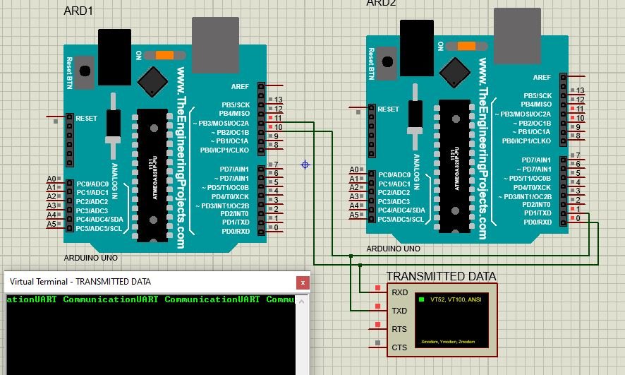
Below figure shows the data sent by Master device and data received by Slave device at pin 11 of Arduino 2.

So data is successfully being transmitted using serial communication and soft serial library of Arduino.
Three most important points should be kept in mind while performing simulated serial communication.
- Tx pin of one Arduino board should be connected to Rx of other Arduino board. If opposite connections are made, Arduino board might get damage.
- Both Arduino boards must share same ground connection from sup
- Also, both Arduino boards should operate at same speed which means baud rate of both board should be same.
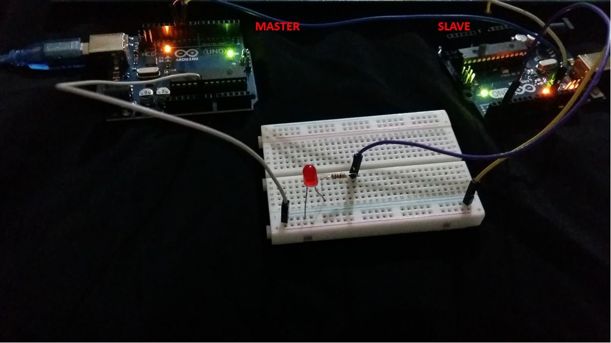
Control an LED via Serial Communication
Let us see another example of serial communication where the master will send either ‘1’ or ‘0’ to the slave. The slave will then receive that data and control an LED connected with its digital pin. We will use Software Serial to communicate between the two boards.
You will require the following components for this project.
Required Components
- Two Arduino UNOs
- One 5mm LED
- One 220 ohm resistor
- Connecting Wires
- Breadboard
Connection Diagram
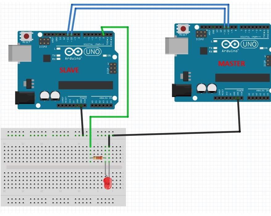
Connect virtual pin Tx of first Arduino board with pin Rx of second Arduino board. Connect virtual pin Rx of first Arduino board with pin Tx of second Arduino board. We will use Software Serial to configure pin 10 as RX and pin 11 as TX.
Anode pin of LED is connected with digital pin 2 (slave) through a 220 ohm current limiting resistor. The cathode pin is grounded.
Also make sure both Arduino boards have their grounds in common.
Code for Master Arduino
#include <SoftwareSerial.h>
SoftwareSerial softSerial(10, 11);

void setup()
{
  softSerial.begin(9600);
  Serial.begin(9600);
}
void loop()
{
  softSerial.print(1);
  Serial.print(1);
  delay(5000);
  softSerial.print(0);
  Serial.print(0);
  delay(5000);
}
Description of Code for Master Arduino
Now lets see how above code works.
First includes the software serial library using its #include files. This line includes the SoftwareSerial.h library.
#include <SoftwareSerial.h>A serial object named as “softSerial” is declared here. Pin 10 will be used as Rx pin and pin 11 will be Tx pin. Using this “softSerial” object all functions of a normal serial connection can be used such as read, write and so on.
SoftwareSerial softSerial (10, 11);Here the baud rate of 9600 is being set for the softSerial object defined above. One important point to note here is that the baud rate of both Arduino boards such as master and slave should be same.
softSerial.begin (9600); Here the master will send the number 1 and 0 to the slave after every 5 seconds.
  softSerial.print(1);

  delay(5000);
  softSerial.print(0);

  delay(5000);
Code for Slave Arduino
#include <SoftwareSerial.h>
SoftwareSerial softSerial(10, 11);

char number  = ' ';
int LED = 2;

void setup()
{
  softSerial.begin(9600);
  Serial.begin(9600);
  pinMode(LED, OUTPUT);
}
void loop()
{
  if (softSerial.available())
  {
    char number = softSerial.read();
    if (number == '0') {
      digitalWrite(LED, LOW);
    }
    if (number == '1') {
      digitalWrite(LED, HIGH);
    }
    Serial.println(number);
  }
}
Description of Code for Slave Arduino
This line includes the SoftwareSerial.h library.
#include <SoftwareSerial.h>SoftwareSerial softSerial () creates a serial object named as “softSerial” is declared here. Pin 10 will be used as Rx pin and pin 11 will be Tx pin. Using this “softSerial” object all functions of a normal serial connection can be used such as read, write and so on.
SoftwareSerial softSerial (10, 11);A char variable called ‘number’ stores the data that the slave will receive from the master.
char number = ' ';
The LED is connected with the slave Arduino’s digital pin 2.
int LED = 2;After that, this line sets the baud to 9600 for soft serial and serial communication.
softSerial.begin(9600);Set the LED pin as an output pin using the pinMode() function. Specify the pin as the first parameter and the mode as the second parameter.
pinMode(LED, OUTPUT);Inside the loop() function, we check if data is present in the buffer. If some data is available, it is stored in variable ‘number.’ Now if the number is ‘0’ then turn the LED OFF. If the number is ‘0’ then turn the LED ON.
The master will send ‘1’ and ‘0’ with a delay of 5 seconds continuously to the slave. Hence, the LED will stay ON for 5 seconds and then OFF for 5 seconds.
void loop()
{
  if (softSerial.available())
  {
    char number = softSerial.read();
    if (number == '0') {
      digitalWrite(LED, LOW);
    }
    if (number == '1') {
      digitalWrite(LED, HIGH);
    }
    Serial.println(number);
  }
}
Hardware Demonstration
To see the demonstration, upload the master and sender codes to the two Arduino boards. But, before uploading code, make sure to select the Arduino board from Tools > Board and also select the correct COM port to which the Arduino board is connected from Tools > Port.

The LED will turn ON and stay ON for 5 seconds before turning OFF for 5 seconds. This continues as the master keeps on sending 1/0 to the slave.

Watch the video below:
Limitations of Software Serial Library
While using software serial communication following limitations should be kept in mind for successfully transmitting and receiving required data.
- Useable Pins
Every pin on the Arduino Board cannot be used as a Tx and Rx pin. For Tx generally, any of the available digital pins can be used but for Rx only pins which are interrupt enabled can be used.
- For Arduino Micro and Leonardo pin 8, 9, 10, 11, 14, 15, 16 can be used as Tx and Rx.
- On the other hand, for Arduino Mega pin 10, 11, 12, 13, 50, 51, 52, 53, 62, 63, 64, 65, 66, 67, 68, 69 can be used as TX and Rx.
- Interference
Simulated software serial communication uses resources of the same hardware. It uses the same timer as used by some other libraries. So some other functions can get effected if simulated serial port is used. The best known interference is with Servo Library.
- Multiple Software Connection:
Using this library, we can have multiple software simulated serial ports. But in this case only one port can receive data at one time. This can cause data loss. However, another software serial library is available which resolves this issue.
Related UART Communication Tutorials:
- SPI Communication Between two Arduino Boards
- UART Communication TM4C123 Tiva C Launchpad
- Serial Communication with Pic Microcontroller
- UART Serial communication with MSP430 microcontroller
Related Projects which used Arduino Serial communication:
- HM-10 Bluetooth Module – Interfacing Example with Arduino
- Sending Data from GSM module to a web server using Arduino
- GSM module interfacing with Arduino: Send and receive SMS
- GSM Based Home Automation project using Arduino
- wifi based home automation system over cloud using Arduino
- Voice Controlled Robot using Arduino and voice recognition app
- WIFI CONTROLLED ROBOT USING ARDUINO and BLYNK
- Bluetooth Based Home Automation project using Arduino
Thanks for this howto. I think the code for the slave is incorrect, the lines
Serial.available())
and
ip=Serial.read();
should use the softSerial object and not Serial otherwise it expects traffic on the serial port.
nice explanation, good place to learn.
I encountered a failure when using pins 10 and 11 on the arduino uno, instead it works for pins 2 and 3