In this tutorial, we will learn to interface a keypad with TM4C123 Tiva C Launchpad and programming in Keil uvision IDE. We will use a 4×4 keypad. But you can use a keypad of any size such as 4×3, 3×4, etc. Because the concepts and process to interface a keypad with Tiva C launchpad will remain the same.
Pre-requisites:
- How to Download and Install Keil uVision for ARM and 8051
- Getting started with Keil uVision: Write your first Program for Tiva LaunchPad
Recommended Components
The following components are used in this project or are helpful for getting started with TM4C123 Tiva C LaunchPad development.
| Component | How it’s used in this project | Buy on Amazon |
|---|---|---|
| TM4C123G Tiva C LaunchPad | The Tiva C board that scans the keypad and drives the LCD. | Check Price |
| Micro USB Cable | Connects the LaunchPad’s onboard debugger to your PC for programming and power. | Check Price |
| 4×4 Membrane Keypad | The matrix keypad whose key presses are detected by row/column scanning. | Check Price |
| 16×2 LCD | Displays the value of the pressed key. | Check Price |
| 10kΩ Potentiometer | Adjusts the LCD contrast. | Check Price |
| Breadboard | Solderless breadboard for building the circuit. | Check Price |
| Jumper Wires | For wiring the keypad and LCD to the LaunchPad. | Check Price |
As an Amazon Associate we earn from qualifying purchases. Prices and availability are accurate as of the date/time indicated and are subject to change.
Keypads Introduction
Keypads consist of push buttons arranged in row and column pattern. That means if we take an example of a 4×4 keypad, it will internally consist of 16 push buttons. As you know, to interface a single push button with a TM4C123 microcontroller, we need one GPIO pin for each push button. If you don’t know how to use push button with TM4C123 Tiva C Launchpad, you can read these posts:
That means to interface a 4×4 keypad with TM4C123, we need to use 16 GPIO pins. No that is not true. Because using 16 GPIO pins only to interface a keypad is the wastage of Tiva Launchpad GPIO pins. To save microcontroller pins, keypads are arranged in the form matrix of rows and columns. For instance, a 4×4 keypad is arranged into a matrix of four rows and four columns. By using this pattern, we will need only 8 GPIO pins of TM4C123 microcontroller. This is exactly the half of original required pins. Therefore, we need four GPIO pins for rows and four for columns.
Keypad Pinout
As mentioned above, we are using a 4×4 keypad. The following figure shows the pinout of the selected keypad.
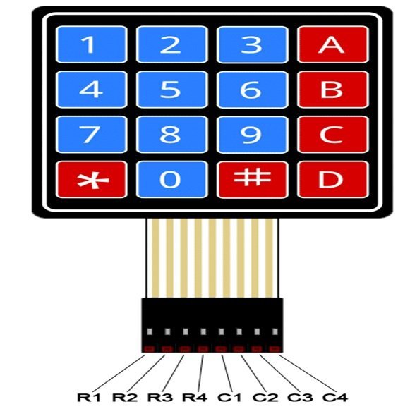
The output connector provides output pins for rows and columns. The first four pins from the left are rows and the last four pins from the right are the columns. To sense the state of each pushbutton from a specific location of a row and a column, we will use GPIO pins of TM4C123 microcontroller as digital input pins.
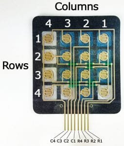
Keypad internal diagram
As discussed earlier, internally a 4×4 keypad consists of a matrix of 4×4 push buttons. When a particular push button is pressed, a particular row and column make contact with each other. In other words, pressing a push button makes connection of one of the row lines with one of the column lines. It allows the current to pass between this row and column. This contact or current flow will be used to detect which particular key is pressed.
How to detect Pressed keys with TM4C123 GPIO Pins?
To detect the pressed button or key of the keypad (4×4, 4×3) with TM4C123, first, we should initialize GPIO pins as digital input pins. Tiva Launchpad scans rows and columns to detect a pressed key according to following steps:
- In the first step, TM4C123 microcontroller configures all the GPIO pins, which connect with rows and columns of keypad, as input lines.
- After that Tiva Launchpad, selects a row and sets it HIGH.
- Then, it scans each of the column lines from the selected row.
If the scanned column lines are low, then no button is pressed in this row. If any of the column lines goes high, Tiva Launchpad already knows to which row it belongs. In this way, the microcontroller finds the respective position of the pressed key in terms of row and column. In programming, we will assign a specific character and numeric value to each key of the keypad.
Connection Diagram TM4C123 and Keypad
Now make connections with the keypad, LCD, and TM4C123 Tiva C Launchpad according to this circuit diagram. The reason we are using a 16×2 LCD. Because we want to display the value of the pressed key on the LCD. In the previous tutorial, we have posted an in-depth guide to interfacing a 16×2 LCD with TM4C123 board. You can refer to this article here:
In this tutorial, we use PORTE and PORTC of TM4C123 to connect a 4×4 keypad. Least significant 4-bits of PORTE are used to connect with 4 rows pins and most significant four bits of PORTC are used to connect with 4 columns of 4×4 keypad.
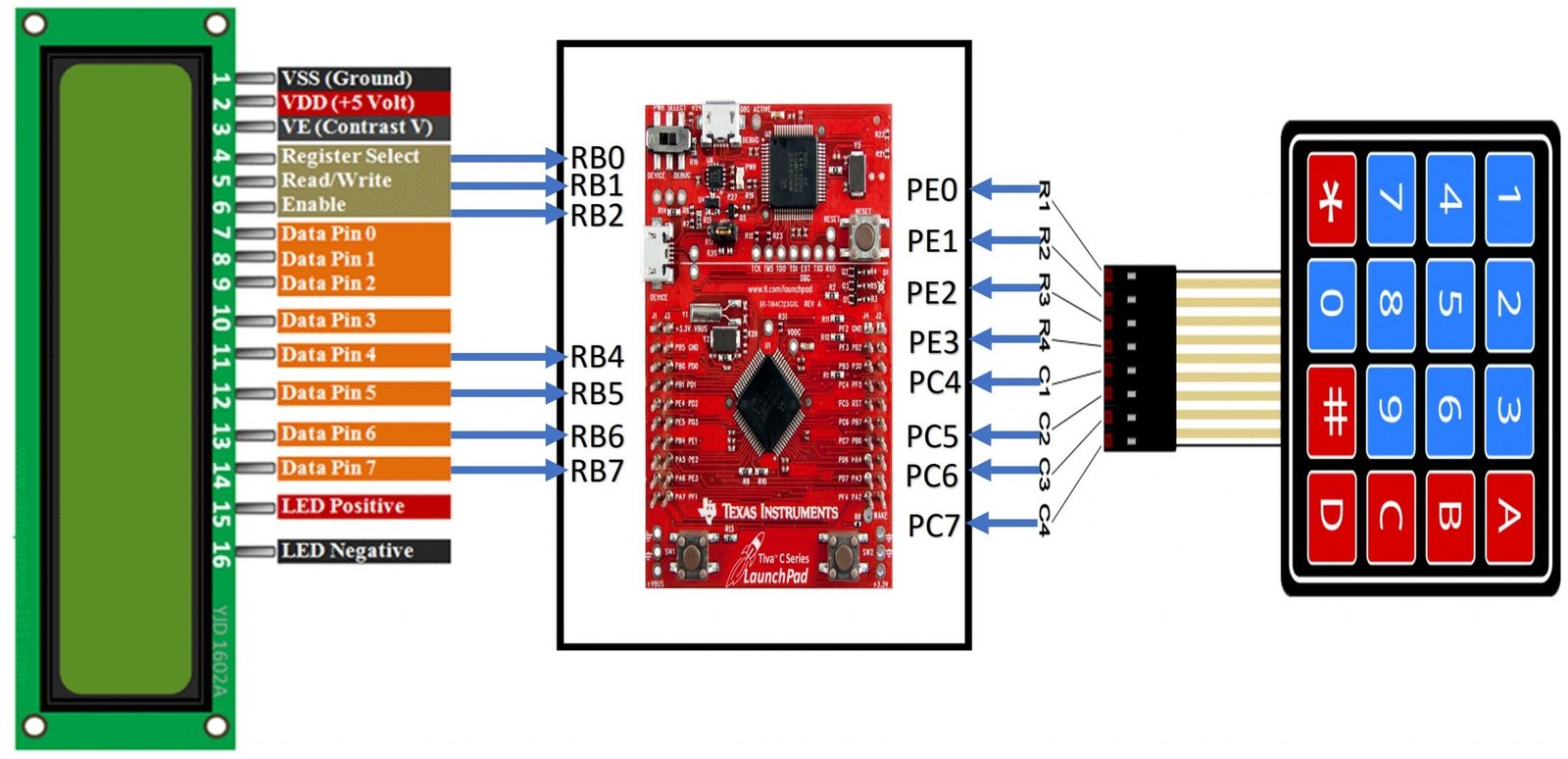
Similarly, make connections with 16×2 LCD according to the above diagram.
4×4 or 4×3 Keypad Programming TM4C123
In this section, we will learn to write a 4×4 keypad program with TM4C123. There are two main parts of keypad coding. Firstly, we need to initialize the GPIO pins of TM4C123 as digital input and digital output pins according to rows and columns of keypad. Secondly, we will write a keypad scan function to detect whenever a user pressed the specific key of the keypad.
2 Dimensional Array to Define Keypad Characters
First, we need to define a 2-dimensional array of key maps. This array consists of values corresponding to each key of the keypad. Therefore, this line defines the array named “symbol” with 16 characters as they mentioned on the actual 4×4 keypad. But you can give them any name you want.
/* Array of 4x4 to define characters which will be printe on specific key pressed */
unsigned  char symbol[RowsSize][ColsSize] = {{ '1', '2',  '3', '+'},
                                                { '4', '5',  '6', '-'},
                                                { '7', '8',  '9', '*'},
                                                { '.', '0',  '=', '/'}};
For example, if you want to design a calculator project with TM4C123 Tiva launchpad and keypad. You can define the array values like this:
 char symbol[ROWS][COLS] = {
  {'1','2','3','4'},
  {'5','6','7','8'},
  {'9','0','+','-'},
  {'.','*','/','='}
};
Keypad Initialization Function
Keypad_Init() function configures the PORTC and PORTE pins, to connect with rows and columns of keypad, as digital output and digital input pins respectively.
Pin PE1 to PE4 are initialized as digital input pins and make connections of PE1 to PE4 with R1 R4 rows of the keypad. Similarly, pins PC4 to PC7 are initialized as digital output pins and make connections of PC4 to PC7 with C1-C4 columns of the keypad. Moreover, we also enable the internal pulldown resistor for PE1 to PEE pins using GPIOE->PDR register.
/* Keypad_Init() configures PORTC and PORTE to scan keypad keys */

void keypad_Init(void)
{
  SYSCTL->RCGCGPIO |= 0x14;        //Enable clock to PORTC and PORTE
  while ((SYSCTL->RCGCGPIO&0x14)==0);  //wait for clock to be setted
  GPIOC->CR  |= 0xF0;             //Allow settings for all pins of PORTC
  GPIOE->CR  |= 0x1E;             //Allow settings for all pins of PORTD
  GPIOE->DIR |= 0x00;             //PE1-PE4 are used with row and set them as digital input pins
  GPIOE->PDR |= 0x1E;             //Enable pull down resistor on PORTE
  GPIOC->DEN |= 0xF0;             //Set PORTC as digital pins
  GPIOE->DEN |= 0x1E;             //Set PORTE as digital pins
}
If you don’t know how to use GPIO pins of TM4C123 Tiva Launchpad as digital input and output pins, you can read these getting started tutorials:
- GPIO Pins of TM4C123
- Push button with TM4C123
Keypad Key Scan Function
This keypad_getkey() function returns the value of a pressed key. This method uses a polling based approach and call back this function whenever we want to scan the keypad. This logic to scan keypad keys consists of two loops. The outer loop scans the columns and the inner loop scans the rows.
/* keypad_getkey() function returns the value of key pressed by the user by traversing columns
and rows respectivley */
char keypad_getkey(void)
{
  while(1)
  {
    for(int i = 0; i < 4; i++)    //Scan columns loop
    {
      GPIOC->DATA = (1U << i+4);
      delay_us(2);
      for(int j = 0; j < 4; j++)  //Scan rows
      {
        if((GPIOE->DATA & 0x1E) & (1U << j+1))
          return symbol[j][i];
      }
    }
  }
}
It makes use of 2 for loops to detect the pressed key. The outer loop finds the column which contains the button had been pressed and the inner for loop to determine the row of that button. After finding the specific position of the key pressed, we return the corresponding value from the 2-dimensional array of characters which we defined above.
Code for Keypad with LCD and TM4C123
This demo code uses a 4×4 keypad and 16×2 LCD to print the value of the pressed key on the LCD. Also, this code is written in Keil uvision. If you don’t know how to use Keil, you can read these tutorials:
#include "TM4C123.h" /* include register definition file of TM4C123GH6PM */
#define LCD GPIOB   /* Define "LCD" as a symbolic name for GPIOB */
#define RS 0x20 /* PORTB BIT5 mask */
#define RW 0x40 /* PORTB BIT6 mask */
#define EN 0x80 /* PORTB BIT7 mask */
#define HIGH 1
#define LOW 0

/*define useful symbolic names for LCD commands */
#define clear_display     0x01
#define returnHome        0x02
#define moveCursorRight   0x06
#define moveCursorLeft    0x08
#define shiftDisplayRight 0x1C
#define shiftDisplayLeft  0x18
#define cursorBlink       0x0F
#define cursorOff         0x0C
#define cursorOn          0x0E
#define Function_set_4bit 0x28
#define Function_set_8bit 0x38
#define Entry_mode        0x06
#define Function_8_bit    0x32
#define Set5x7FontSize    0x20
#define FirstRow          0x80
unsigned int ncols = 0;
unsigned int nrows = 0;

/* Defines the size of rows and columns of keypad */
#define  RowsSize  4
#define  ColsSize  4

/* Array of 4x4 to define characters which will be printe on specific key pressed */
unsigned  char symbol[RowsSize][ColsSize] = {{ '1', '2',  '3', '+'},
                                                { '4', '5',  '6', '-'},
                                                { '7', '8',  '9', '*'},
                                                { '.', '0',  '=', '/'}};

/* prototypes of LCD functions */
void delay_ms(int n); /* mili second delay function */
void delay_us(int n); /* micro second delay function */
void LCD_init(void);  /* LCD initialization function */
void LCD_Cmd(unsigned char command); /*Used to send commands to LCD */
void LCD_Write_Char(unsigned char data); /* Writes ASCII character */
void LCD_Write_Nibble(unsigned char data, unsigned char control); /* Writes 4-bits */
void LCD_String (char *str);	/* Send string to LCD function */
void keypad_Init(void); /* Keypad initialization */
char keypad_getkey(void); /*Scan and detect key pressed */

/* Main function calls LCD and keypad initialization functions */
int main()
{
keypad_Init(); //Initialize keypad and TM4C123 GPIO pins
 LCD_init(); // initialize 16x2 LCD
 LCD_Cmd(clear_display); // Clear LCD screen
 LCD_Cmd(FirstRow); /* Force cursor to beginning of first row */
 while(1)
    {
    char value = keypad_getkey(); //get the key pressed value
    LCD_Write_Char(value); // display key value on LCD
    delay_ms(1000);  // delay of one second
    }

}

/* LCD and GPIOB initialization Function */
void LCD_init(void)
{
 SYSCTL->RCGCGPIO |=(1<<1); /* Enable Clock to GPIOB */
 LCD->DIR |=0xFF; /* Set GPIOB all pins a digital output pins */
 LCD->DEN |=0xFF; /* Declare GPIOB pins as digital pins */

 LCD_Cmd(Set5x7FontSize);  /* select 5x7 font size and 2 rows of LCD */
 LCD_Cmd(Function_set_4bit); /* Select 4-bit Mode of LCD */
 LCD_Cmd(moveCursorRight); /* shift cursor right */
 LCD_Cmd(clear_display); /* clear whatever is written on display */
 LCD_Cmd(cursorBlink);  /* Enable Display and cursor blinking */

}

void LCD_Cmd(unsigned char command)
{
    LCD_Write_Nibble(command & 0xF0, 0);   /* Write upper nibble to LCD */
    LCD_Write_Nibble(command << 4, 0);     /* Write lower nibble to LCD */

    if (command < 4)
        delay_ms(2);         /* 2ms delay for commands 1 and 2 */
    else
        delay_us(40);        /* 40us delay for other commands */
}


void LCD_Write_Nibble(unsigned char data, unsigned char control)
{

    data &= 0xF0;       /* Extract upper nibble for data */
    control &= 0x0F;    /* Extract lower nibble for control */
    LCD->DATA = data | control;       /* Set RS and R/W to zero for write operation */
    LCD->DATA = data | control | EN;  /* Provide Pulse to Enable pin to perform wite operation */
    delay_us(0);
    LCD->DATA = data; /*Send data */
    LCD->DATA = 0; /* stop writing data to LCD */
}
void LCD_Write_Char(unsigned char data)
{
    LCD_Write_Nibble(data & 0xF0, RS);    /* Write upper nibble to LCD and RS = 1 to write data */
    LCD_Write_Nibble(data << 4, RS);      /* Write lower nibble to LCD and RS = 1 to write data */
    delay_us(40);
}


void LCD_String (char *str)	/* Send string to LCD function */
{
	int i;
	for(i=0;str[i]!=0;i++)  /* Send each char of string till the NULL */
	{
		LCD_Write_Char(str[i]);  /* Call LCD data write */
	}
}

/* Keypad_Init() configures PORTC and PORTE to scan keypad keys */

void keypad_Init(void)
{
  SYSCTL->RCGCGPIO |= 0x14;        //Enable clock to PORTC and PORTE
  while ((SYSCTL->RCGCGPIO&0x14)==0);  //wait for clock to be setted
  GPIOC->CR  |= 0xF0;             //Allow settings for all pins of PORTC
  GPIOE->CR  |= 0x1E;             //Allow settings for all pins of PORTD
  GPIOE->DIR |= 0x00;             //PE1-PE4 are used with row and set them as digital input pins
  GPIOE->PDR |= 0x1E;             //Enable pull down resistor on PORTE
  GPIOC->DEN |= 0xF0;             //Set PORTC as digital pins
  GPIOE->DEN |= 0x1E;             //Set PORTE as digital pins
}

/* keypad_getkey() function returns the value of key pressed by the user by traversing columns
and rows respectivley */
char keypad_getkey(void)
{
  while(1)
  {
    for(int i = 0; i < 4; i++)    //Scan columns loop
    {
      GPIOC->DATA = (1U << i+4);
      delay_us(2);
      for(int j = 0; j < 4; j++)  //Scan rows
      {
        if((GPIOE->DATA & 0x1E) & (1U << j+1))
          return symbol[j][i];
      }
    }
  }
}

/* Mili seconds delay function */
void delay_ms(int n)
{
 int i,j;
 for(i=0;i<n;i++)
 for(j=0;j<3180;j++)
 {}
}

/* Micro seconds delay function */
void delay_us(int n)
{
 int i,j;
 for(i=0;i<n;i++)
 for(j=0;j<3;j++)
 {}

}
Conclusion
In this tutorial, we’ve covered the essential steps to interface a 4×4 keypad with the TM4C123 Tiva C Launchpad using Keil uVision IDE. We explored the wiring and configuration required to connect the keypad and how to program the Tiva C Launchpad to read inputs from it. Although this example uses a 4×4 keypad, the principles and techniques discussed are applicable to keypads of various sizes, such as 4×3 or 3×4. By understanding these concepts, you can adapt the process to different keypad configurations, enhancing your ability to integrate user input into your embedded projects effectively.
Related Tutorials:
- 4×4 keypad interfacing with Arduino Uno R3 with code
- KEYPAD INTERFACING 8051 MICROCONTROLLER with code
- Electronic lock using pic microcontroller
- KEYPAD INTERFACING WITH PIC16F877A MICROCONTROLLER
- Automatic electronic bell for school using pic microcontroller
- SPI Communication TM4C123
- HC-SR04 Ultrasonic Sensor Interfacing with TM4C123
- Frequency Measurement using TM4C123
- ADC TM4C123G Tiva C Launchpad
- MPU6050 Gyroscope Accelerometer sensor interfacing with TM4C123G
Sir,ı could ask you a question,if you would mind.The keypad gets values as char,but ı need them as integers for my project.How can ı convert char values to integer in keilv5
Thank you
In C++, stoi() function is used to convert char to int or you can use type casting. But the way is used to stoi() function. Check if stio() function is available in keil.
Sİr how can ı configure this code to use on putty screen ı just need to read number from putty screen with keypad.
Sir when I try to configure this codeto use with putty screen I just use keypad function part of this code and uart part of your other code but my JTAG had some problem than I reset my card with lm flash programmer it can be reason according to my research using c pins somethime cause this error. Could you share a code please how we can use keypad with putty. Than your all kind answer.
Hi sir, how can do this with uart and putty
Hi
Excellent contribution, thank you very much.
I have a question, I hope you can help me.
In the case of the function keypad_getkey as you mention it uses a polling based approach, my question is, how can I make this function but with interrupt approach
TY
🙂
void keypad_Init(void){
SYSCTL->RCGCGPIO |= 0x14; //Enable clock to PORTC and PORTE
while ((SYSCTL->RCGCGPIO&0x14)==0); //wait for clock to be setted
GPIOC->CR |= 0xF0; //Allow settings for all pins of PORTC
GPIOE->CR |= 0x1E; //Allow settings for all pins of PORTD
GPIOC->DIR |= (1<<4) | (1<<5) | (1<<6) | (1<DIR &= ~(1<<1) & ~(1<<2) & ~(1<<3) & ~(1<PDR |= 0x1E; //Enable pull down resistor on PORTE
GPIOC->DEN |= 0xF0; //Set PORTC as digital pins
GPIOE->DEN |= 0x1E; //Set PORTE as digital pins
}
#define RS 0x01 /* PORTB BIT0 mask */
#define RW 0x02 /* PORTB BIT1 mask */
#define EN 0x04 /* PORTB BIT2 mask */