In this tutorial, we will learn how to interface a microSD card with STM32 Blue Pill using the microSD card module using STM32CubeIDE. This module provides an SPI interface to connect an SD card module with any microcontroller which supports the SPI communication interface. Using a microSD card becomes very handy for applications where we need to store files of large sizes.
We will show you how to handle files on the microSD card including creating a new file, writing to a file, finding storage space, etc. Storage data including text, video, audio, CSV, HTML, JavaScript, and CSS files can all be conveniently stored on the microSD card. It is one of the most reliable and practical ways to store data in devices such as mobile phones, laptops, and personal computers.
We have similar guides with other microcontrollers also:
- Interface Micro SD Card Module with Raspberry Pi Pico
- MicroSD Card Module with ESP32 using Arduino IDE
- BME280 Data Logger with Arduino and Micro SD Card
- Micro SD Card Interfacing with Arduino using MicroSD Module
Recommended Components
The following components are used in this project or are helpful for getting started with STM32 Blue Pill development.
| Component | How it’s used in this project | Buy on Amazon |
|---|---|---|
| STM32F103C8T6 Blue Pill Board | The STM32 board reading and writing the SD card over SPI. | Check Price |
| ST-Link V2 Programmer | SWD programmer/debugger used to flash code onto the Blue Pill. | Check Price |
| MicroSD Card Module | The SPI SD card module interfaced in this project. | Check Price |
| MicroSD Card | FAT32-formatted card the file is written to. | Check Price |
| Breadboard & Jumper Wires | For wiring the SD card module to the Blue Pill. | Check Price |
As an Amazon Associate we earn from qualifying purchases. Prices and availability are accurate as of the date/time indicated and are subject to change.
MicroSD Card Module Introduction
The microSD card modules are designed to communicate with the MicroSD cards. These connectors provide the required hardware and pinout to connect SD cards with microcontrollers such as STM32, ESP32, Arduino, ESP8266, Raspberry Pi, etc. Although, they are compatible with almost all SD cards which are commonly used in cell phones. But they can handle a maximum of 16GB capacity microSD cards and only 2GB capacity for standard SD cards.
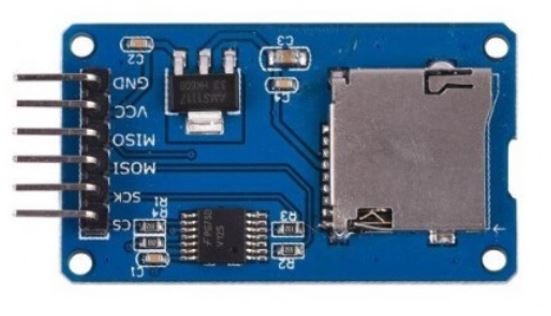
With the help of these modules, we will be able to read and write data to and from SD cards through the SPI communication protocol. There are several different types of microSD card modules easily available in the market. But, the one which we will be using in this article is shown below:
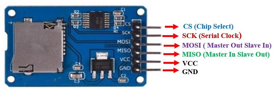
Pinout
This microSD card module has 6 terminals consisting of SPI and power supply terminals. Below you can view the pinout of this module with some description of the individual pins.
| Pin Name | Description |
|---|---|
| GND | This is the ground pin which should be connected with the ground pin of STM32 Blue Pill. |
| VCC | This pin supplies power to the module. The power supply of ~4.5V-5.5V. The adapter also consists of a 3.3V voltage regulator circuit as well. |
| CS | This is the Chip Select pin for SPI communication. |
| MOSI | This is called the ‘Master Out Slave In.’ It is used as the SPI input to the module. |
| SCK | This is called the ‘Serial Clock’ pin which is used in SPI serial clock output. |
| MISO | This is called the ‘Master in Slave Out.’ It is used as the SPI output from the module. |
MicroSD card module Interfacing with STM32 Blue Pill
We will require the following components for this project.
- STM32 Blue Pill board
- MicroSD card
- MicroSD card module
- Connecting Wires
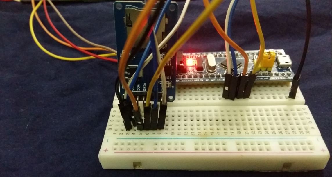
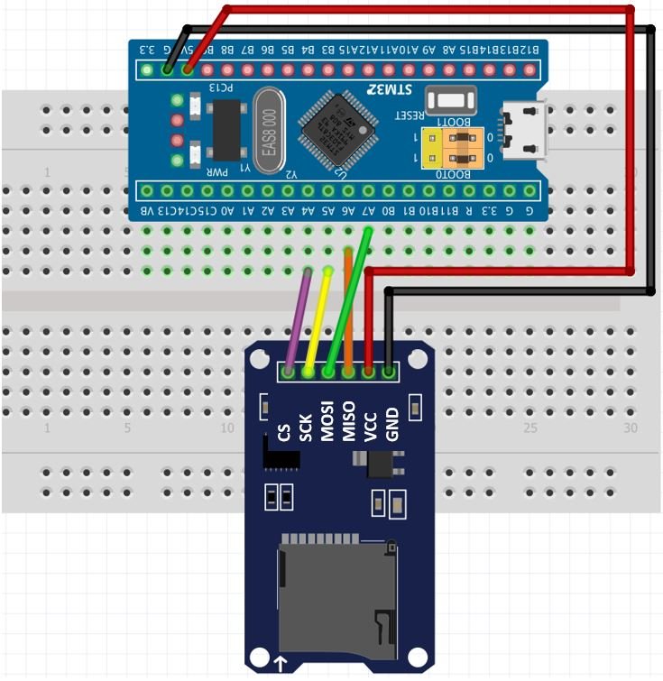
The table below shows the connections between the two devices that we will be using:
| MicroSD card module | STM32 Blue Pill |
|---|---|
| GND | GND |
| VCC | 5V |
| CS | PA4 |
| MOSI | PA7 (SPI1_MOSI) |
| SCK | PA5 (SPI1_SCK) |
| MISO | PA6 (SPI1_MISO) |
As shown from the table, we will connect the VCC terminal of MicroSD card module with 5V pin of STM32 Blue Pill. Both grounds will be common. We are using SPI1 pins of Blue Pill to connect with the Microsd card module.
Now, as we know how to interface the microSD card module and the STM32 Blue Pill together let us learn how to prepare the microSD card to handle files.
You can learn about STM32 Blue Pill SPI here:
Formatting the MicroSD card
Make sure your microSD card is formatted as FAT32. We will have to follow a series of steps to accomplish it successfully.
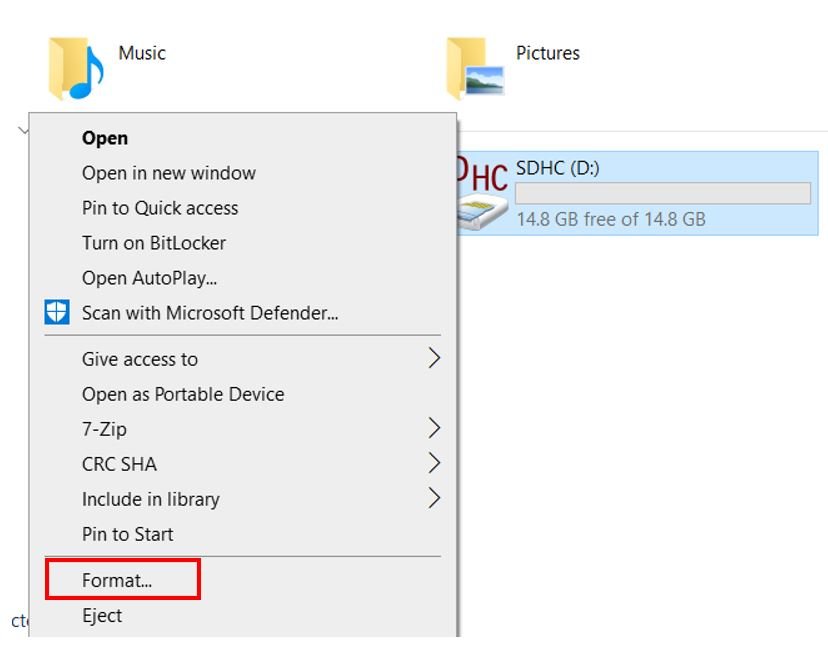
- First, insert your microSD card in your laptop/computer. Now go to ‘This PC’ and click on SD card icon. Then click on Format by right clicking the SD card icon.
- The following window will appear. Select FAT32 from the dialog box of ‘File System’ and click on ‘START.’

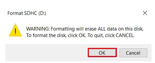
- You will receive a warning message that formatting will erase all previous data saved on the microSD card. Click ‘OK.’
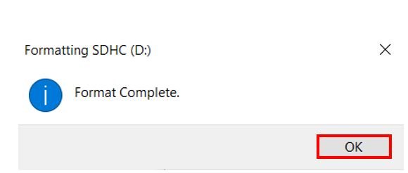
- After a few moments, your microSD card will be formatted successfully. Click ‘OK.’
MicroSD Card Module with STM32 Blue Pill Code
We will use STM32CubeIDE to program our STM32 board. Open the IDE and head over to a new project.
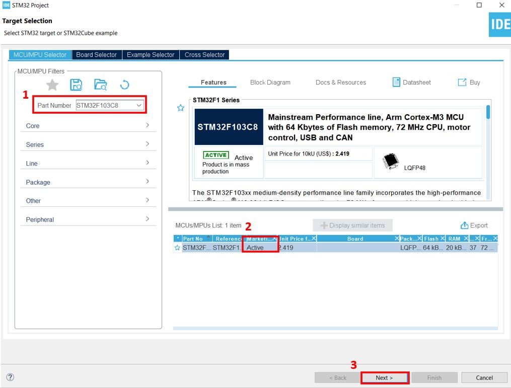
Then for the target selection, specify the STM32 Blue Pill board number. After that click on any column as shown in the picture below. Then click the ‘Next’ button.
Specify the name of your project then click ‘Finish’ to complete the setup of your project.
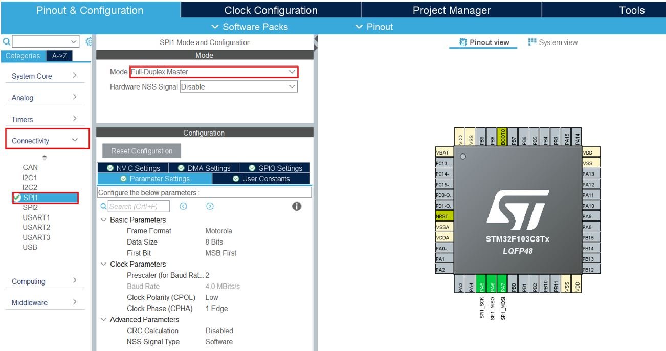
Now head over to Connectivity > SPI1. Select the SPI mode as ‘Full Duplex Master.’
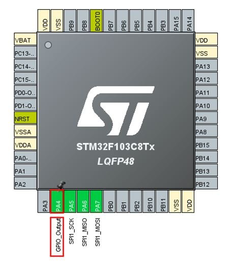
Configure PA4 as GPIO_Output.
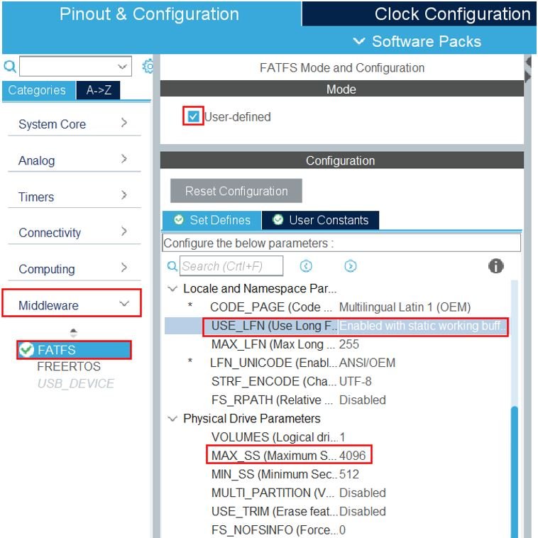
Now head over to Middleware > FATFS. In the Mode section, tick User-defined. Then click ‘Set Defines’ in the Configuration section. Scroll down and enable with static working buffer for USE_LFN. Also, set MAX_SS as 4096.
Now we will save our file. Press Ctrl + S. The following window will appear. Click ‘Yes.’ This will generate a template code for you.

Another window will appear that will ask if you want to open the perspective. Click ‘Yes.’

MicroSD Card Module Libraries
As we are working with a SD card with our STM32 Blue Pill, we will require the fatfs_sd.h library. Let us show you how to add the required libraries and make some modifications in some files which is necessary.
fatfs_sd.h
Go to Core > Inc and create a new file called ‘fatfs_sd.h‘ Copy the following code from this link and save it to this file.
fatfs_sd.c
Similarly, head over to Core > Src and create a new file called ‘fatfs_sd.c‘ Copy the following code from this link and save it to this file.
Modifications
Go to Core > Src and replace the code in the stm32f1xx_it.c file with the code given below:
/* USER CODE BEGIN Header */
/**
  ******************************************************************************
  * @file    stm32f1xx_it.c
  * @brief   Interrupt Service Routines.
  ******************************************************************************
  * @attention
  *
  * Copyright (c) 2022 STMicroelectronics.
  * All rights reserved.
  *
  * This software is licensed under terms that can be found in the LICENSE file
  * in the root directory of this software component.
  * If no LICENSE file comes with this software, it is provided AS-IS.
  *
  ******************************************************************************
  */
/* USER CODE END Header */

/* Includes ------------------------------------------------------------------*/
#include "main.h"
#include "stm32f1xx_it.h"
/* Private includes ----------------------------------------------------------*/
/* USER CODE BEGIN Includes */
/* USER CODE END Includes */

/* Private typedef -----------------------------------------------------------*/
/* USER CODE BEGIN TD */

/* USER CODE END TD */

/* Private define ------------------------------------------------------------*/
/* USER CODE BEGIN PD */

/* USER CODE END PD */

/* Private macro -------------------------------------------------------------*/
/* USER CODE BEGIN PM */

/* USER CODE END PM */

/* Private variables ---------------------------------------------------------*/
/* USER CODE BEGIN PV */

/* USER CODE END PV */

/* Private function prototypes -----------------------------------------------*/
/* USER CODE BEGIN PFP */

/* USER CODE END PFP */

/* Private user code ---------------------------------------------------------*/
/* USER CODE BEGIN 0 */
extern uint16_t Timer1, Timer2;

/* USER CODE END 0 */

/* External variables --------------------------------------------------------*/

/* USER CODE BEGIN EV */

/* USER CODE END EV */

/******************************************************************************/
/*           Cortex-M3 Processor Interruption and Exception Handlers          */
/******************************************************************************/
/**
  * @brief This function handles Non maskable interrupt.
  */
void NMI_Handler(void)
{
  /* USER CODE BEGIN NonMaskableInt_IRQn 0 */

  /* USER CODE END NonMaskableInt_IRQn 0 */
  /* USER CODE BEGIN NonMaskableInt_IRQn 1 */
  while (1)
  {
  }
  /* USER CODE END NonMaskableInt_IRQn 1 */
}

/**
  * @brief This function handles Hard fault interrupt.
  */
void HardFault_Handler(void)
{
  /* USER CODE BEGIN HardFault_IRQn 0 */

  /* USER CODE END HardFault_IRQn 0 */
  while (1)
  {
    /* USER CODE BEGIN W1_HardFault_IRQn 0 */
    /* USER CODE END W1_HardFault_IRQn 0 */
  }
}

/**
  * @brief This function handles Memory management fault.
  */
void MemManage_Handler(void)
{
  /* USER CODE BEGIN MemoryManagement_IRQn 0 */

  /* USER CODE END MemoryManagement_IRQn 0 */
  while (1)
  {
    /* USER CODE BEGIN W1_MemoryManagement_IRQn 0 */
    /* USER CODE END W1_MemoryManagement_IRQn 0 */
  }
}

/**
  * @brief This function handles Prefetch fault, memory access fault.
  */
void BusFault_Handler(void)
{
  /* USER CODE BEGIN BusFault_IRQn 0 */

  /* USER CODE END BusFault_IRQn 0 */
  while (1)
  {
    /* USER CODE BEGIN W1_BusFault_IRQn 0 */
    /* USER CODE END W1_BusFault_IRQn 0 */
  }
}

/**
  * @brief This function handles Undefined instruction or illegal state.
  */
void UsageFault_Handler(void)
{
  /* USER CODE BEGIN UsageFault_IRQn 0 */

  /* USER CODE END UsageFault_IRQn 0 */
  while (1)
  {
    /* USER CODE BEGIN W1_UsageFault_IRQn 0 */
    /* USER CODE END W1_UsageFault_IRQn 0 */
  }
}

/**
  * @brief This function handles System service call via SWI instruction.
  */
void SVC_Handler(void)
{
  /* USER CODE BEGIN SVCall_IRQn 0 */

  /* USER CODE END SVCall_IRQn 0 */
  /* USER CODE BEGIN SVCall_IRQn 1 */

  /* USER CODE END SVCall_IRQn 1 */
}

/**
  * @brief This function handles Debug monitor.
  */
void DebugMon_Handler(void)
{
  /* USER CODE BEGIN DebugMonitor_IRQn 0 */

  /* USER CODE END DebugMonitor_IRQn 0 */
  /* USER CODE BEGIN DebugMonitor_IRQn 1 */

  /* USER CODE END DebugMonitor_IRQn 1 */
}

/**
  * @brief This function handles Pendable request for system service.
  */
void PendSV_Handler(void)
{
  /* USER CODE BEGIN PendSV_IRQn 0 */

  /* USER CODE END PendSV_IRQn 0 */
  /* USER CODE BEGIN PendSV_IRQn 1 */

  /* USER CODE END PendSV_IRQn 1 */
}

/**
  * @brief This function handles System tick timer.
  */
void SysTick_Handler(void)
{
  /* USER CODE BEGIN SysTick_IRQn 0 */
	if(Timer1 > 0)
		Timer1--;
	if(Timer2 > 0)
		Timer2--;

  /* USER CODE END SysTick_IRQn 0 */
  HAL_IncTick();
  /* USER CODE BEGIN SysTick_IRQn 1 */

  /* USER CODE END SysTick_IRQn 1 */
}

/******************************************************************************/
/* STM32F1xx Peripheral Interrupt Handlers                                    */
/* Add here the Interrupt Handlers for the used peripherals.                  */
/* For the available peripheral interrupt handler names,                      */
/* please refer to the startup file (startup_stm32f1xx.s).                    */
/******************************************************************************/

/* USER CODE BEGIN 1 */

/* USER CODE END 1 */
Similarly, go to FATFS > Target and replace the code in the user_diskio.c file with the following code:
/* USER CODE BEGIN Header */
/**
 ******************************************************************************
  * @file    user_diskio.c
  * @brief   This file includes a diskio driver skeleton to be completed by the user.
  ******************************************************************************
  * @attention
  *
  * Copyright (c) 2022 STMicroelectronics.
  * All rights reserved.
  *
  * This software is licensed under terms that can be found in the LICENSE file
  * in the root directory of this software component.
  * If no LICENSE file comes with this software, it is provided AS-IS.
  *
  ******************************************************************************
  */
 /* USER CODE END Header */

#ifdef USE_OBSOLETE_USER_CODE_SECTION_0
/*
 * Warning: the user section 0 is no more in use (starting from CubeMx version 4.16.0)
 * To be suppressed in the future.
 * Kept to ensure backward compatibility with previous CubeMx versions when
 * migrating projects.
 * User code previously added there should be copied in the new user sections before
 * the section contents can be deleted.
 */
/* USER CODE BEGIN 0 */
/* USER CODE END 0 */
#endif

/* USER CODE BEGIN DECL */

/* Includes ------------------------------------------------------------------*/
#include <string.h>
#include "ff_gen_drv.h"

/* Private typedef -----------------------------------------------------------*/
/* Private define ------------------------------------------------------------*/

/* Private variables ---------------------------------------------------------*/
/* Disk status */
static volatile DSTATUS Stat = STA_NOINIT;

/* USER CODE END DECL */

/* Private function prototypes -----------------------------------------------*/
DSTATUS USER_initialize (BYTE pdrv);
DSTATUS USER_status (BYTE pdrv);
DRESULT USER_read (BYTE pdrv, BYTE *buff, DWORD sector, UINT count);
#if _USE_WRITE == 1
  DRESULT USER_write (BYTE pdrv, const BYTE *buff, DWORD sector, UINT count);
#endif /* _USE_WRITE == 1 */
#if _USE_IOCTL == 1
  DRESULT USER_ioctl (BYTE pdrv, BYTE cmd, void *buff);
#endif /* _USE_IOCTL == 1 */

Diskio_drvTypeDef  USER_Driver =
{
  USER_initialize,
  USER_status,
  USER_read,
#if  _USE_WRITE
  USER_write,
#endif  /* _USE_WRITE == 1 */
#if  _USE_IOCTL == 1
  USER_ioctl,
#endif /* _USE_IOCTL == 1 */
};

/* Private functions ---------------------------------------------------------*/

/**
  * @brief  Initializes a Drive
  * @param  pdrv: Physical drive number (0..)
  * @retval DSTATUS: Operation status
  */
DSTATUS USER_initialize (
	BYTE pdrv           /* Physical drive nmuber to identify the drive */
)
{
  /* USER CODE BEGIN INIT */
    return SD_disk_initialize(pdrv);
  /* USER CODE END INIT */
}

/**
  * @brief  Gets Disk Status
  * @param  pdrv: Physical drive number (0..)
  * @retval DSTATUS: Operation status
  */
DSTATUS USER_status (
	BYTE pdrv       /* Physical drive number to identify the drive */
)
{
  /* USER CODE BEGIN STATUS */
    return SD_disk_status(pdrv);
  /* USER CODE END STATUS */
}

/**
  * @brief  Reads Sector(s)
  * @param  pdrv: Physical drive number (0..)
  * @param  *buff: Data buffer to store read data
  * @param  sector: Sector address (LBA)
  * @param  count: Number of sectors to read (1..128)
  * @retval DRESULT: Operation result
  */
DRESULT USER_read (
	BYTE pdrv,      /* Physical drive nmuber to identify the drive */
	BYTE *buff,     /* Data buffer to store read data */
	DWORD sector,   /* Sector address in LBA */
	UINT count      /* Number of sectors to read */
)
{
  /* USER CODE BEGIN READ */
    return SD_disk_read(pdrv, buff, sector, count);
  /* USER CODE END READ */
}

/**
  * @brief  Writes Sector(s)
  * @param  pdrv: Physical drive number (0..)
  * @param  *buff: Data to be written
  * @param  sector: Sector address (LBA)
  * @param  count: Number of sectors to write (1..128)
  * @retval DRESULT: Operation result
  */
#if _USE_WRITE == 1
DRESULT USER_write (
	BYTE pdrv,          /* Physical drive nmuber to identify the drive */
	const BYTE *buff,   /* Data to be written */
	DWORD sector,       /* Sector address in LBA */
	UINT count          /* Number of sectors to write */
)
{
  /* USER CODE BEGIN WRITE */
  /* USER CODE HERE */
    return SD_disk_write(pdrv, buff, sector, count);
  /* USER CODE END WRITE */
}
#endif /* _USE_WRITE == 1 */

/**
  * @brief  I/O control operation
  * @param  pdrv: Physical drive number (0..)
  * @param  cmd: Control code
  * @param  *buff: Buffer to send/receive control data
  * @retval DRESULT: Operation result
  */
#if _USE_IOCTL == 1
DRESULT USER_ioctl (
	BYTE pdrv,      /* Physical drive nmuber (0..) */
	BYTE cmd,       /* Control code */
	void *buff      /* Buffer to send/receive control data */
)
{
  /* USER CODE BEGIN IOCTL */
   return SD_disk_ioctl(pdrv, cmd, buff);
  /* USER CODE END IOCTL */
}
#endif /* _USE_IOCTL == 1 */
STM32 MicroSD Card Module STM32CubeIDE Code
We will show you how to create a new .txt file in the microSD card and write to it. Now let us look at our main.c file that was generated.
Inside the main.c file, make sure the following code is part of your script by including the lines of code given below.
#include "main.h"
#include "fatfs.h"

FATFS fs;
FIL fil;


SPI_HandleTypeDef hspi1;

void SystemClock_Config(void);
static void MX_GPIO_Init(void);
static void MX_SPI1_Init(void);

int main(void)
{
  HAL_Init();

  SystemClock_Config();

  MX_GPIO_Init();
  MX_SPI1_Init();
  MX_FATFS_Init();

  HAL_Delay(500);
   f_mount(&fs, "", 0);
   f_open(&fil, "test.txt", FA_OPEN_ALWAYS | FA_WRITE | FA_READ);
   f_lseek(&fil, fil.fsize);
   f_puts("This is an example text to check SD Card Module with STM32 Blue Pill\n", &fil);
   f_close(&fil);

  while (1)
  {

  }

}
Working of the Code
We start off by including the fatfs.h library to access the APIs for FATFS.
#include "fatfs.h"We create the file system object called ‘fs’ and the file object structure ‘fil.’
FATFS fs;
FIL fil;
Inside the main function, first all the peripherals are initialized, system clock is configured and all the configured peripherals are initialized.
  HAL_Init();

  SystemClock_Config();

  MX_GPIO_Init();
  MX_SPI1_Init();
  MX_FATFS_Init();
Mount
After a slight delay, we fount the filesystem. We call f_mount() function that provides the work area to the FatFs module. This function takes in three parameters:
- the pointer to the filesystem object. In our case it is ‘&fs.’
- the pointer to the logical drive number. In our case the string does not consist of a drive number which denotes the default drive.
- the mounting option. In our case it is ‘0’ which means it will be mounted on the first access to the volume. If ‘1’ was specified as a parameter instead then it meant that the volume would be force mounted to check if it is ready to work.
f_mount(&fs, "", 0);Open
Then we call f_open() to create or open a file. This function takes in three parameters:
- The pointer to the blank file object structure.
- The pointer to the null-terminated string that denotes the file name to open or create.
- Lastly, the mode flags. They denote the type of access and open method for the file. The table below shows the combination of different flags which may be used.
| Flags | Description |
| FA_READ | To read data from a file. |
| FA_WRITE | To write data to a file. If it is combined with FA_READ then both read-write access is granted. |
| FA_OPEN_EXISTING | Open an already existing file. If the file does not exist, then this function fails. |
| FA_CREATE_NEW | Create a new file. If the file already exists, then this function fails. |
| FA_CREATE_ALWAYS | Create a new file. If the file already exists, then the file gets overwritten. |
| FA_OPEN_ALWAYS | Create a new file, if the file does not exist. If the file exists, then it opens the file. |
| FA_OPEN_APPEND | Create a new file, if the file does not exist. If the file exists, then it opens the file. The read/write pointer is set at end of the file. |
Here we are creating a file called ‘test.txt’ and giving it read-write access.
f_open(&fil, "test.txt", FA_OPEN_ALWAYS | FA_WRITE | FA_READ);Next, we call the f_lseek() function which will transfer the file read/write pointer of an open file object. Moreover, it can also be used to increase the size of the file. This function takes in two parameters:
- The pointer to the open file object.
- The byte offset from top of the file which will be used to configure the read/write pointer.
f_lseek(&fil, fil.fsize);Write
Then we write a string to the file using f_puts() function. This function takes in two parameters:
- The pointer to the null terminated string to be written.
- The pointer to the open file object structure.
Here we are writing the string “This is an example text to check SD Card Module with STM32 Blue Pill” to the file.
f_puts("This is an example text to check SD Card Module with STM32 Blue Pill\n", &fil);After writing to the file, we close the open file using the function f_close(). This function takes in a single parameter which is the pointer to the open file object structure that is to be closed.
f_close(&fil);main.c file
This is how a complete main.c file will be after modification.
#include "main.h"
#include "fatfs.h"

FATFS fs;
FIL fil;

SPI_HandleTypeDef hspi1;

void SystemClock_Config(void);
static void MX_GPIO_Init(void);
static void MX_SPI1_Init(void);

int main(void)
{
  HAL_Init();

  SystemClock_Config();

  MX_GPIO_Init();
  MX_SPI1_Init();
  MX_FATFS_Init();

  HAL_Delay(500);
   f_mount(&fs, "", 0);
   f_open(&fil, "test.txt", FA_OPEN_ALWAYS | FA_WRITE | FA_READ);
   f_lseek(&fil, fil.fsize);
   f_puts("This is an example text to check SD Card Module with STM32 Blue Pill\n", &fil);
   f_close(&fil);


  while (1)
  {

  }

}

/**
  * @brief System Clock Configuration
  * @retval None
  */
void SystemClock_Config(void)
{
  RCC_OscInitTypeDef RCC_OscInitStruct = {0};
  RCC_ClkInitTypeDef RCC_ClkInitStruct = {0};

  /** Initializes the RCC Oscillators according to the specified parameters
  * in the RCC_OscInitTypeDef structure.
  */
  RCC_OscInitStruct.OscillatorType = RCC_OSCILLATORTYPE_HSI;
  RCC_OscInitStruct.HSIState = RCC_HSI_ON;
  RCC_OscInitStruct.HSICalibrationValue = RCC_HSICALIBRATION_DEFAULT;
  RCC_OscInitStruct.PLL.PLLState = RCC_PLL_ON;
  RCC_OscInitStruct.PLL.PLLSource = RCC_PLLSOURCE_HSI_DIV2;
  RCC_OscInitStruct.PLL.PLLMUL = RCC_PLL_MUL9;
  if (HAL_RCC_OscConfig(&RCC_OscInitStruct) != HAL_OK)
  {
    Error_Handler();
  }
  /** Initializes the CPU, AHB and APB buses clocks
  */
  RCC_ClkInitStruct.ClockType = RCC_CLOCKTYPE_HCLK|RCC_CLOCKTYPE_SYSCLK
                              |RCC_CLOCKTYPE_PCLK1|RCC_CLOCKTYPE_PCLK2;
  RCC_ClkInitStruct.SYSCLKSource = RCC_SYSCLKSOURCE_PLLCLK;
  RCC_ClkInitStruct.AHBCLKDivider = RCC_SYSCLK_DIV1;
  RCC_ClkInitStruct.APB1CLKDivider = RCC_HCLK_DIV2;
  RCC_ClkInitStruct.APB2CLKDivider = RCC_HCLK_DIV1;

  if (HAL_RCC_ClockConfig(&RCC_ClkInitStruct, FLASH_LATENCY_1) != HAL_OK)
  {
    Error_Handler();
  }
}

/**
  * @brief SPI1 Initialization Function
  * @param None
  * @retval None
  */
static void MX_SPI1_Init(void)
{

  /* USER CODE BEGIN SPI1_Init 0 */

  /* USER CODE END SPI1_Init 0 */

  /* USER CODE BEGIN SPI1_Init 1 */

  /* USER CODE END SPI1_Init 1 */
  /* SPI1 parameter configuration*/
  hspi1.Instance = SPI1;
  hspi1.Init.Mode = SPI_MODE_MASTER;
  hspi1.Init.Direction = SPI_DIRECTION_2LINES;
  hspi1.Init.DataSize = SPI_DATASIZE_8BIT;
  hspi1.Init.CLKPolarity = SPI_POLARITY_LOW;
  hspi1.Init.CLKPhase = SPI_PHASE_1EDGE;
  hspi1.Init.NSS = SPI_NSS_SOFT;
  hspi1.Init.BaudRatePrescaler = SPI_BAUDRATEPRESCALER_2;
  hspi1.Init.FirstBit = SPI_FIRSTBIT_MSB;
  hspi1.Init.TIMode = SPI_TIMODE_DISABLE;
  hspi1.Init.CRCCalculation = SPI_CRCCALCULATION_DISABLE;
  hspi1.Init.CRCPolynomial = 10;
  if (HAL_SPI_Init(&hspi1) != HAL_OK)
  {
    Error_Handler();
  }
  /* USER CODE BEGIN SPI1_Init 2 */

  /* USER CODE END SPI1_Init 2 */

}

/**
  * @brief GPIO Initialization Function
  * @param None
  * @retval None
  */
static void MX_GPIO_Init(void)
{
  GPIO_InitTypeDef GPIO_InitStruct = {0};

  /* GPIO Ports Clock Enable */
  __HAL_RCC_GPIOA_CLK_ENABLE();

  /*Configure GPIO pin Output Level */
  HAL_GPIO_WritePin(GPIOA, GPIO_PIN_4, GPIO_PIN_RESET);

  /*Configure GPIO pin : PA4 */
  GPIO_InitStruct.Pin = GPIO_PIN_4;
  GPIO_InitStruct.Mode = GPIO_MODE_OUTPUT_PP;
  GPIO_InitStruct.Pull = GPIO_NOPULL;
  GPIO_InitStruct.Speed = GPIO_SPEED_FREQ_LOW;
  HAL_GPIO_Init(GPIOA, &GPIO_InitStruct);

}

/* USER CODE BEGIN 4 */

/* USER CODE END 4 */

/**
  * @brief  This function is executed in case of error occurrence.
  * @retval None
  */
void Error_Handler(void)
{
  /* USER CODE BEGIN Error_Handler_Debug */
  /* User can add his own implementation to report the HAL error return state */
  __disable_irq();
  while (1)
  {
  }
  /* USER CODE END Error_Handler_Debug */
}

#ifdef  USE_FULL_ASSERT
/**
  * @brief  Reports the name of the source file and the source line number
  *         where the assert_param error has occurred.
  * @param  file: pointer to the source file name
  * @param  line: assert_param error line source number
  * @retval None
  */
void assert_failed(uint8_t *file, uint32_t line)
{
  /* USER CODE BEGIN 6 */
  /* User can add his own implementation to report the file name and line number,
     ex: printf("Wrong parameters value: file %s on line %d\r\n", file, line) */
  /* USER CODE END 6 */
}
#endif /* USE_FULL_ASSERT */
Save the main.c file after modifying it. Now we are ready to build our project.
Building the Project
To build our project press Ctrl + B or go to Project > Build All.
Your project will start building. After a few moments, your project will be successfully built if there are no errors.
Connecting ST-Link Programmer with STM32
Now as we have successfully built our project let us move ahead and upload the code to our STM32 board. To do that, first we will have to connect our Blue Pill STM32 with a ST-Link programmer. We will be using ST-Link V2.

This will provide an interface between our computer and our STM32 board. It consists of 10 pins. We will be using pin2 SWDIO, pin6 SWCLK, pin4 GND, and pin8 3.3V to connect with our STM32 board. The SWDIO is the data input/output pin and the SWCLK is the clock pin. Follow the pin configuration given on the ST-LINK V2 to identify each pin.
Follow the table below to connect both devices correctly.
| STM32 | ST-LINK V2 |
| VCC 3.3V pin | pin8 3.3V |
| SWDIO pin | pin2 SWDIO |
| SWCLK pin | pin6 SWCLK |
| GND pin | pin4 GND |

Additionally, move the BOOT jumper to the right to enable the microcontroller to go into programming mode.

- Now connect your ST-LINK V2 with your computer via the USB port. Both devices will power ON.
- Next press the RUN button in the IDE. The ‘Edit configuration’ window will open up. Click ‘OK’.
- After a few moments, the code will be successfully sent to the STM32 board. Otherwise, press the RESET button on your STM32 board.
- Now to bring the Blue pill back to normal mode make sure you bring the BOOT jumper back at its place.
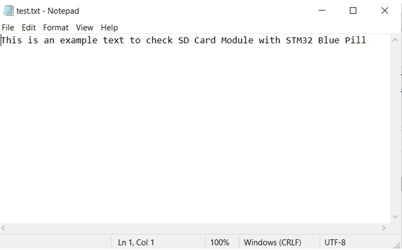
Once the code is uploaded to the board, take the microSD card out of the module and insert it in your system to view the test.txt file.
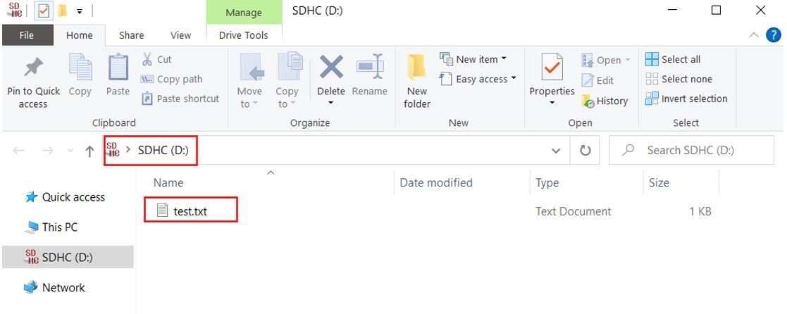
Open the test.txt file. Inside it, you can view the string that we wrote to the file:
You may also like to read:
- DHT22 Sensor with STM32 Blue Pill using STM32CubeIDE
- HC-SR04 Ultrasonic Sensor with STM32 Blue Pill using STM32CubeIDE
- SSD1306 OLED with STM32 Blue Pill using STM32CubeIDE
- HC-05 Bluetooth Module with STM32 Blue Pill using STM32CubeIDE
- STM32 Blue Pill Timer Encoder Mode with Rotary Encoder Example
Other MicroSD related projects:
- Data Logger with Raspberry Pi Pico and Micro SD Card
- ESP32-CAM Capture Photo and Save to MicroSD Card
- BME280 Data Logger with Arduino and Micro SD Card
- DHT22 Data Logger with Arduino and Micro SD Card
- GPS Data Logger with Arduino and Micro SD Card – GPS Tracker
- ESP32 Web Server Hosting Files from Micro SD card (Arduino IDE)
I am a beginner with BluePill and STM32CubeIDE.
The IDE gives me an error. In the file fatfs sd.c is
#include “stm32f4xx_hal.h”
The IDE reports
../Core/Src/fatfs_sd.c:5:10: fatal error: stm32f4xx_hal.h: No such file or directory
The same error is also reported in the data logger program. In the directory Core/Inc is file stm32f4xx_hal_conf.h
Is that the file? Should I rename it?
The problem is for some reason it´s including headers for STM32 F4 family and Blue Pill is STM32F1 family. Check you choose the correct MCU or if you copied any file that has that header instead the f1 (stm32f1xx_hal.h).
Please use the code given in the article, it contains modified files for STM32F1.
Links are also updated for STM32F1.
Hi! The code in fatfs_sd.c and stm32f4xx_it.c files when using it for STM32F411RETx. The errors and are thrown. Thank you!
Hi! The code in fatfs_sd.c and stm32f4xx_it.c files when using it for STM32F411RETx. The errors and are thrown. Thank you!
errors are undefined reference to ‘Timer1’ and ‘Timer2’
For people trying this code and running into the errors I did while compiling:
in fatfs_sd.c add somewhere near the top:
#define SD_CS_GPIO_Port GPIOA
#define SD_CS_Pin GPIO_PIN_4
in stm32f1xx_it.c change:
extern uint16_t Timer1, Timer2;
into:
volatile uint16_t Timer1, Timer2;
For me it compiles now without errors. Have not tested the actual functionality yet.