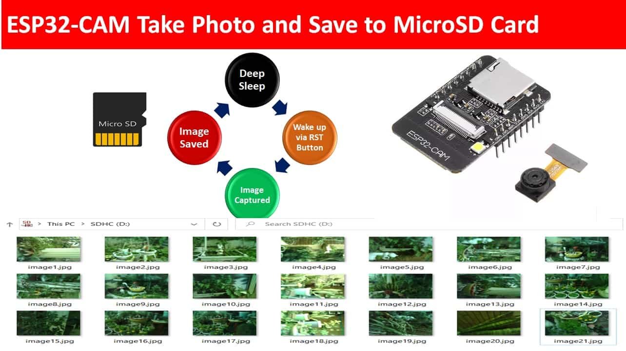
This ESP32-CAM guide shows the users an easy way to capture photos through ESP32-CAM and save it to microSD card. In order to save battery, ESP32-CAM will remain in sleep mode for most of the time and wake up from deep sleep whenever the RST button will be pressed. After wake up from deep sleep, ESP32-CAM will capture a photo and save the photo to the microSD card.
You can know more about ESP32-CAM and its pinout here:
Recommended Components
The following components are used in this project or are helpful for building it with the ESP32.
| Component | How it’s used in this project | Buy on Amazon |
|---|---|---|
| ESP32 Development Board | General ESP32 board for development alongside the camera module. | Check Price |
| ESP32-CAM board | Captures the photos saved to the microSD card. | Check Price |
| FTDI / USB-TTL programmer | Required to upload code to the ESP32-CAM, which has no onboard USB. | Check Price |
| MicroSD card | Stores the captured photos in the ESP32-CAM onboard slot. | Check Price |
| Micro USB Cable | Powers the boards during development. | Check Price |
| Jumper Wires | Wire the ESP32-CAM to the FTDI programmer for flashing. | Check Price |
As an Amazon Associate we earn from qualifying purchases. Prices and availability are accurate as of the date/time indicated and are subject to change.
ESP32-CAM Introduction
The ESP32-CAM development board is another member of the ESP32 module family. It is an inexpensive board consisting of an ESP32-S chip, an OV2640 video camera, and a micro-SD card slot that is extremely useful in major IoT applications. It can be used with advanced projects where facial recognition, image tracking, wireless monitoring, and identification are required.
Key Features
The ESP32-CAM consists of the ESP32 chip so it shares the same specifications as that of the generic ESP32 module. The key features of the ESP32-CAM module are given below:
- 802.11b/g/n Wi-Fi, Classic Bluetooth 4.2 and BLE
- Consists of two 32-bit LX6 CPUs
- Has 7 stage pipeline architecture
- Equipped with Hall, on-chip and temperature sensor
- Main frequency ranges from 80MHz-240MHz
- Supports UART/SPI/I2C/PWM/ADC/DAC interfaces
- 520 KB SRAM and 4MB PSRAM
- 160MHz clock speed with computing power up to 600 DMIPS
- Supports OV2640/OV7670 video cameras with built-in flash, image Wi-Fi upload, TF card, FOTA upgrades and various sleep modes
- FreeRTOS and embedded Lwip
ESP32-CAM OV2640 Video Camera Specifications
As mentioned before, the ESP32-CAM module consists of an OV2640 camera module. It has the following specifications:
- 2 Megapixel sensor
- UXGA 1622×1200
- Output formats include: YUV422, YUV420, RGB565, RGB555
- 15-60 fps image transfer rate
Project Overview
The ESP32-CAM board has a built-in SD card connector which can used to connect a microSD card. We will capture photos through this development board and save them to the microSD card. Moreover, the photos captured will be saved in the ESP32-CAM flash memory. This will help us distinguish the amount of pictures taken. To save power, the microcontroller will remain in deep sleep mode and will wake up when the RST button will be pressed and then captures the image.
Follow the figure below which shows the whole project process:

You can read about ESP32 sleep modes here:
- ESP32 Deep Sleep Mode and Wake Up Sources using Arduino IDE
- MicroPython: ESP32 Deep Sleep Mode and Wake Up Sources
For this project we will require the following components:
Required Components
- ESP32-CAM board with camera
- FTDI Programmer
- microSD card
- Connecting Wires
- External 5V Power Supply (optional)
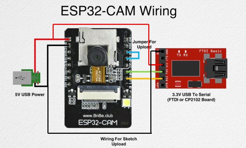
Connecting ESP32-CAM with FTDI programmer
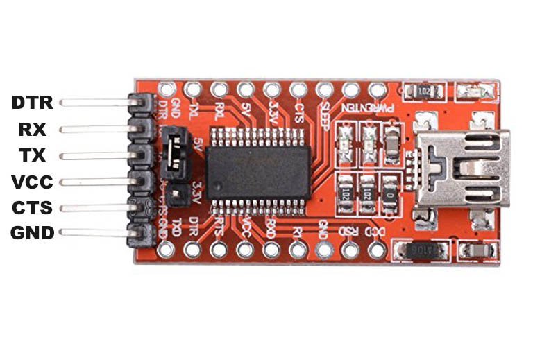
Unlike the ESP32 development board, the ESP32-CAM does not come with the USB port attached to it. So to upload a program sketch to the ESP32-CAM, we will need to use an FTDI programmer (USB to TTL Serial converter).
You can learn more about this FTDI cable here:
The table shows the connections between the ESP32-CAM and FTDI programmer:
| ESP32-CAM | FTDI Programmer |
| 5V | VCC |
| UOR (GPIO3) | TX |
| UOT (GPIO1) | RX |
| GND | GND |
Connect the 5V pin of ESP32-CAM with the VCC pin of the FTDI programmer to power up. Both grounds of the two devices will be connected in common. The TX pin of the FTDI programmer will be connected with UOR (GPIO3) of ESP32-CAM. Likewise, the RX pin will be connected with the UOT (GPIO1) of the ESP32-CAM module.
Additionally, you will need to connect GPIO0 with GND to enable the ESP32-CAM module to go in flashing mode. Remove this connection after uploading the program sketch to the module.
On some ESP32-CAM boards, you will get a brown-out detector error which is due to the insufficient voltage provided by the FTDI cable. In that case, you should connect an external 5V power supply to ESP32 as shown below:
Formatting the MicroSD card
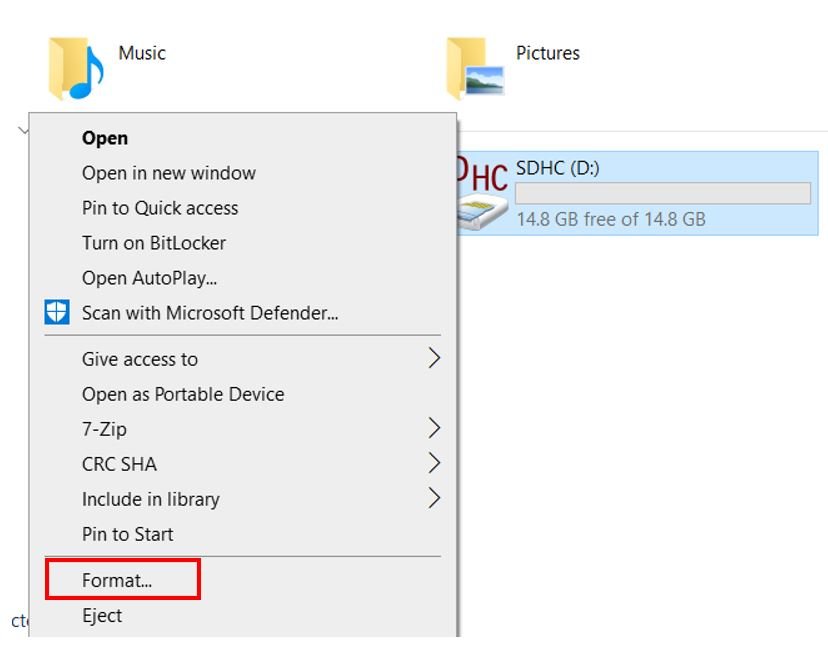
As we have to use our microSD card in Arduino IDE so we would have to format it as FAT32. We will have to follow a series of steps to accomplish it successfully.
- First, insert your microSD card in your laptop/computer. Now go to ‘This PC’ and click on SD card icon. Then click on Format by right clicking the SD card icon.
- The following window will appear. Select FAT32 from the dialog box of ‘File System’ and click on ‘START.’

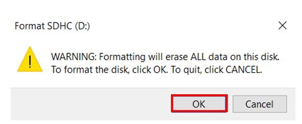
- You will receive a warning message that formatting will erase all previous data saved on the microSD card. Click ‘OK.’
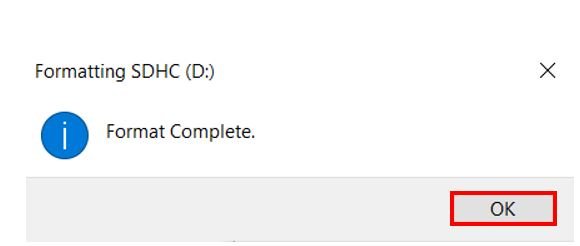
- After a few moments, your microSD card will be formatted successfully. Click ‘OK.’
Setting up Arduino IDE
Before we proceed further, you should make sure that you have the latest version of Arduino IDE installed on your system. Moreover, you should also install an ESP32 add-on in Arduino IDE. If your IDE does not have the plugin installed you can visit the link below:
Installing ESP32 library in Arduino IDE and upload code
Arduino Sketch
Open your Arduino IDE and go to File > New to open a new file. Copy the code given below in that file.
#include "esp_camera.h"
#include "Arduino.h"
#include "FS.h"
#include "SD_MMC.h"
#include "soc/soc.h"
#include "soc/rtc_cntl_reg.h"
#include "driver/rtc_io.h"
#include <EEPROM.h>

// define the number of bytes you want to access
#define EEPROM_SIZE 1

// Pin definition for CAMERA_MODEL_AI_THINKER
#define PWDN_GPIO_NUM     32
#define RESET_GPIO_NUM    -1
#define XCLK_GPIO_NUM      0
#define SIOD_GPIO_NUM     26
#define SIOC_GPIO_NUM     27
#define Y9_GPIO_NUM       35
#define Y8_GPIO_NUM       34
#define Y7_GPIO_NUM       39
#define Y6_GPIO_NUM       36
#define Y5_GPIO_NUM       21
#define Y4_GPIO_NUM       19
#define Y3_GPIO_NUM       18
#define Y2_GPIO_NUM        5
#define VSYNC_GPIO_NUM    25
#define HREF_GPIO_NUM     23
#define PCLK_GPIO_NUM     22

int imageNum = 0;

void setup() {
  WRITE_PERI_REG(RTC_CNTL_BROWN_OUT_REG, 0); //disable brownout detector

  Serial.begin(115200);

  camera_config_t config;
  config.ledc_channel = LEDC_CHANNEL_0;
  config.ledc_timer = LEDC_TIMER_0;
  config.pin_d0 = Y2_GPIO_NUM;
  config.pin_d1 = Y3_GPIO_NUM;
  config.pin_d2 = Y4_GPIO_NUM;
  config.pin_d3 = Y5_GPIO_NUM;
  config.pin_d4 = Y6_GPIO_NUM;
  config.pin_d5 = Y7_GPIO_NUM;
  config.pin_d6 = Y8_GPIO_NUM;
  config.pin_d7 = Y9_GPIO_NUM;
  config.pin_xclk = XCLK_GPIO_NUM;
  config.pin_pclk = PCLK_GPIO_NUM;
  config.pin_vsync = VSYNC_GPIO_NUM;
  config.pin_href = HREF_GPIO_NUM;
  config.pin_sscb_sda = SIOD_GPIO_NUM;
  config.pin_sscb_scl = SIOC_GPIO_NUM;
  config.pin_pwdn = PWDN_GPIO_NUM;
  config.pin_reset = RESET_GPIO_NUM;
  config.xclk_freq_hz = 20000000;
  config.pixel_format = PIXFORMAT_JPEG;

  if(psramFound()){
    config.frame_size = FRAMESIZE_UXGA; // FRAMESIZE_ + QVGA|CIF|VGA|SVGA|XGA|SXGA|UXGA
    config.jpeg_quality = 10;
    config.fb_count = 2;
  } else {
    config.frame_size = FRAMESIZE_SVGA;
    config.jpeg_quality = 12;
    config.fb_count = 1;
  }

  // Init Camera
  esp_err_t err = esp_camera_init(&config);
  if (err != ESP_OK) {
    Serial.printf("Camera init failed with error 0x%x", err);
    return;
  }

  if(!SD_MMC.begin()){
    Serial.println("SD Card Mount Failed");
    return;
  }

  uint8_t cardType = SD_MMC.cardType();
  if(cardType == CARD_NONE){
    Serial.println("No SD Card attached");
    return;
  }

  camera_fb_t * fb = NULL;

  // Capture picture
  fb = esp_camera_fb_get();
  if(!fb) {
    Serial.println("Camera Failed to Capture");
    return;
  }
  // initialize EEPROM
  EEPROM.begin(EEPROM_SIZE);
  imageNum = EEPROM.read(0) + 1;

  String path = "/image" + String(imageNum) +".jpg";

  fs::FS &fs = SD_MMC;
  Serial.printf("Picture file name: %s\n", path.c_str());

  File file = fs.open(path.c_str(), FILE_WRITE);
  if(!file){
    Serial.println("Failed to open file in writing mode");
  }
  else {
    file.write(fb->buf, fb->len);
    Serial.printf("Saved file to path: %s\n", path.c_str());
    EEPROM.write(0, imageNum);
    EEPROM.commit();
  }
  file.close();
  esp_camera_fb_return(fb);

  pinMode(4, OUTPUT);
  digitalWrite(4, LOW);
  rtc_gpio_hold_en(GPIO_NUM_4);

  delay(2000);
  Serial.println("ESP32-CAM going to sleep...");
  delay(2000);
  esp_deep_sleep_start();
}

void loop() {

}
How the Code Works?
We will start off by including all the necessary libraries required for this project including the camera functionality, EEPROM and microSD card functionality.
#include "esp_camera.h"
#include "Arduino.h"
#include "FS.h"
#include "SD_MMC.h"
#include "soc/soc.h"
#include "soc/rtc_cntl_reg.h"
#include "driver/rtc_io.h"
#include <EEPROM.h>
Then we will define the EEPROM size. We are defining a single byte that we will use in the flash memory. This will allow us to save 256 image numbers.
#define EEPROM_SIZE 1The following definitions are for OV2640 camera module pins. We are using CAMERA_MODEL_AI_THINKER.
// Pin definition for CAMERA_MODEL_AI_THINKER
#define PWDN_GPIO_NUM     32
#define RESET_GPIO_NUM    -1
#define XCLK_GPIO_NUM      0
#define SIOD_GPIO_NUM     26
#define SIOC_GPIO_NUM     27
#define Y9_GPIO_NUM       35
#define Y8_GPIO_NUM       34
#define Y7_GPIO_NUM       39
#define Y6_GPIO_NUM       36
#define Y5_GPIO_NUM       21
#define Y4_GPIO_NUM       19
#define Y3_GPIO_NUM       18
#define Y2_GPIO_NUM        5
#define VSYNC_GPIO_NUM    25
#define HREF_GPIO_NUM     23
#define PCLK_GPIO_NUM     22
Then we will create an integer variable called ‘imageNum.’ This is the number of the image. Initially we have set to to 0.
int imageNum = 0;setup()
Inside the setup() function we will open the serial communication at a baud rate of 115200.
Serial.begin(115200);The following code sets the OV2640 camera module and the settings required for the photo capturing.
 camera_config_t config;
  config.ledc_channel = LEDC_CHANNEL_0;
  config.ledc_timer = LEDC_TIMER_0;
  config.pin_d0 = Y2_GPIO_NUM;
  config.pin_d1 = Y3_GPIO_NUM;
  config.pin_d2 = Y4_GPIO_NUM;
  config.pin_d3 = Y5_GPIO_NUM;
  config.pin_d4 = Y6_GPIO_NUM;
  config.pin_d5 = Y7_GPIO_NUM;
  config.pin_d6 = Y8_GPIO_NUM;
  config.pin_d7 = Y9_GPIO_NUM;
  config.pin_xclk = XCLK_GPIO_NUM;
  config.pin_pclk = PCLK_GPIO_NUM;
  config.pin_vsync = VSYNC_GPIO_NUM;
  config.pin_href = HREF_GPIO_NUM;
  config.pin_sscb_sda = SIOD_GPIO_NUM;
  config.pin_sscb_scl = SIOC_GPIO_NUM;
  config.pin_pwdn = PWDN_GPIO_NUM;
  config.pin_reset = RESET_GPIO_NUM;
  config.xclk_freq_hz = 20000000;
  config.pixel_format = PIXFORMAT_JPEG;

  if(psramFound()){
    config.frame_size = FRAMESIZE_UXGA; // FRAMESIZE_ + QVGA|CIF|VGA|SVGA|XGA|SXGA|UXGA
    config.jpeg_quality = 10;
    config.fb_count = 2;
  } else {
    config.frame_size = FRAMESIZE_SVGA;
    config.jpeg_quality = 12;
    config.fb_count = 1;
  }
Initializing ESP32-CAM:
 esp_err_t err = esp_camera_init(&config);
  if (err != ESP_OK) {
    Serial.printf("Camera init failed with error 0x%x", err);
    return;
  }
The following lines of code will initialize the microSD card using the begin() function on the SD filesystem. It will start the SPI communication.
 if(!SD_MMC.begin()){
    Serial.println("SD Card Mount Failed");
    return;
  }

  uint8_t cardType = SD_MMC.cardType();
  if(cardType == CARD_NONE){
    Serial.println("No SD Card attached");
    return;
  }
Next, we will capture an image using ESP32-CAM. The following lines enable us to do that.
 camera_fb_t * fb = NULL;
  fb = esp_camera_fb_get();
  if(!fb) {
    Serial.println("Camera Failed to Capture");
    return;
  }
Then we will initialize EEPROM using the begin() method and pass the EERPROM_SIZE that we defined earlier as a parameter inside it.
EEPROM.begin(EEPROM_SIZE);
The imageNum will be set to the latest number saved in the EEPROM plus 1.
imageNum = EEPROM.read(0) + 1;The following line sets the path of the image. It will consist of /image1.jpg for the first image, /image2.jpg for the second image and so on.
String path = "/image" + String(imageNum) +".jpg";Next we will save the image in the microSD card on the specified path. The EEPROM will save the latest image number to monitor the number of images captured.
 fs::FS &fs = SD_MMC;
  Serial.printf("Picture file name: %s\n", path.c_str());

  File file = fs.open(path.c_str(), FILE_WRITE);
  if(!file){
    Serial.println("Failed to open file in writing mode");
  }
  else {
    file.write(fb->buf, fb->len);
    Serial.printf("Saved file to path: %s\n", path.c_str());
    EEPROM.write(0, imageNum);
    EEPROM.commit();
  }
  file.close();
  esp_camera_fb_return(fb);
The onboard LED of ESP32-CAM will turn ON at the time the picture will be captured. It will then turn off and the board will go to deep sleep mode.
  pinMode(4, OUTPUT);
  digitalWrite(4, LOW);
  rtc_gpio_hold_en(GPIO_NUM_4);

  delay(2000);
  Serial.println("ESP32-CAM going to sleep...");
  delay(2000);
  esp_deep_sleep_start();
loop()
The loop() function is empty because it is not needed for this project. The setup() function will run once every time the ESP32-CAM resets.
Uploading and Demonstration
Now, we are ready to compile and upload the code to our ESP32-CAM. Make sure the FTDI programmer is properly connected with the module and GPIO0 is grounded as well.
Choose the correct board and COM port before uploading your code to the ESP32-CAM board. Go to Tools > Board and select ESP32 AI Thinker.
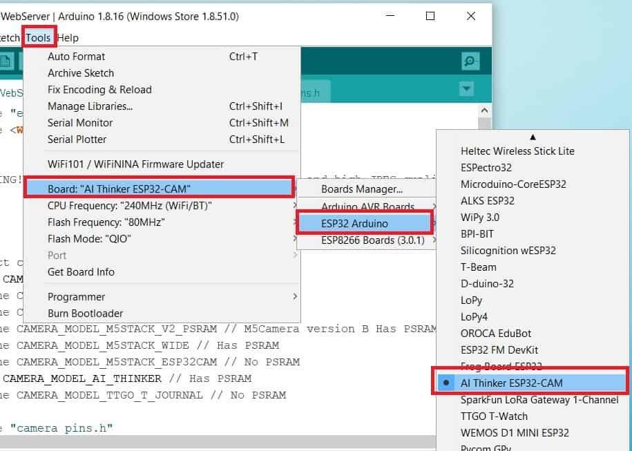
Next, go to Tools > Port and select the appropriate port through which your board is connected.
Click on the upload button to upload the code into the ESP32-CAM board.
If you view Connecting….._____….._____….. in the error window, press the RESET button present on the ESP32-CAM as shown below:

After you have successfully uploaded your code to the board, remove the connecting wire from GPIO0 and GND.
Now open the serial monitor and press the RESET button on the ESP32-CAM.
This will allow you to take a photo that will get saved in the microSD card. The ESP32-CAM then goes to deep sleep and wakes up only when the Reset button is pressed.
Below you can view the serial monitor when the eighth picture gets captured and then gets saved to the microSD card.

Take the microSD card out of the module and insert it in your system to view all the images. Here you can view 21 photos that we captured via ESP32-CAM which were saved to our microSD card.

You may also like to read:
Thank you for this simple code, as I am trying to use my esp32 Cam with my telescope adapter and three things I would like to modify this code for. 1- no LED on, I am trying to use it with dark environment so wanted to disable the LED. tried to comment out this section of the code and 2- also don’t let it go to sleep:
pinMode(4, OUTPUT);
digitalWrite(4, LOW);
rtc_gpio_hold_en(GPIO_NUM_4);
delay(2000);
Serial.println(“ESP32-CAM going to sleep…”);
delay(2000);
esp_deep_sleep_start();
but still LED enabled and still goes to sleep…
I would like to use a remote RST button to avoid shaking the telescope while I press the reset button.. Any pointers would be appreciated.. Thanks