This tutorial is a guide to AI thinker ESP32-CAM development board. We will discuss pinout, features, and specifications and see how to get started with ESP32- CAM development board.
Recommended Components
The following parts are used in this article, along with a generic electronics kit that is handy for building and testing the circuit.
| Component | How it’s used | Buy on Amazon |
|---|---|---|
| ESP32-CAM (AI-Thinker) board | The AI-Thinker ESP32-CAM board with OV2640 camera this article covers. | Check Price |
| Electronic component assortment kit (1390 pcs) | A handy assortment of resistors, capacitors, LEDs, diodes and transistors for building circuits. | Check Price |
| Digital multimeter (AstroAI) | Measures voltage, current, resistance and checks continuity while you build and debug. | Check Price |
| Breadboard | Solderless base for prototyping the circuit. | Check Price |
| Jumper Wires | Make the connections on the breadboard. | Check Price |
As an Amazon Associate we earn from qualifying purchases. Prices and availability are accurate as of the date/time indicated and are subject to change.
ESP32-CAM AI-Thinker Introduction
The world has been revolving around IoTs i.e., Internet of Things for quite a while now. From the hobbyists to the innovators, everyone is interested in Smart technology, designing different prototypes and products, and launching them in the market. ESP32 Series chips are one of the popular intelligent modules for IoTs. ESP32-CAM AI-Thinker is the advanced version of ESP8266-01 launched by Espressif with many features. The ultra-small, low-power module comes with two high-performance 32-bit LX6 CPUs with a 7-stage pipeline architecture.
Peripherals
ESP32-CAM has integrated with Wi-Fi, Bluetooth and can be used with OV2640 or OV7670 cameras. The ESP32 IC has high-resolution ADCs, SPI, I2C, and UART protocols for information communication. The module has an inbuilt Hall sensor, temperature sensor, and touch sensors, and watchdog timers. RTC can be operated in different modes. The module has a maximum clock frequency of 160 MHz that means the computing power up to 600 DMPIS. Furthermore, it is quite durable and reliable when it comes to internet connectivity.
Applications
ESP32-CAM AI-Thinker module has a never-ending list of applications like home automation, intelligent devices, positioning systems, security systems and perfect for IoT applications.
ESP32-CAM AI-Thinker Components
This development board is a 27*40.5*4.5 DIP style PCB Board. The following figure shows the components of the ESP32-CAM board from both top and bottom side.
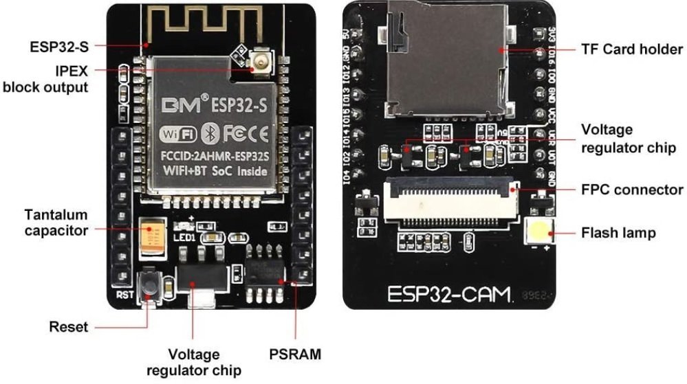
ESP32-CAM AI-Thinker module consists of different parts. These areas described below:
ESP32-S Chip: The module is a main chip contains two high-performance 32-bit LX6 CPUs with a 7-stage pipeline architecture and used for all the processing and functioning.
IPEX block output: The printed IPEX connects GSM antennas to transmit signals.
Tantalum capacitor: The tantalum capacitor is majorly used on small size modules. They are durable and provide power supply filtering for fine signal quantity.
Reset button: When pressed, the reset button restarts the code executed on the module.
Voltage regulator chip: The voltage regulator chip on the module maintains the output voltage despite the fluctuations in the input supply. It regulates the voltage to 3.3 volts.
PSRAM: A low-power Pseudo-Random Access Memory of 4MB is incorporated in the module for fast processing of the instructions. It helps the camera to run smoothly.
TF Card Holder: ESP32 series are embedded with a micro-SD card holder to store the data. All the transmission takes place through the Serial Peripheral Interface.
FPC connector: To mount the camera, the ESP32 module contains a flexible printed circuit connector. Their fine pitch is responsible for signal reliability.
Flash Light: The flash lamp produces electric pulses which work as a flash for the camera so that it can capture clear images.
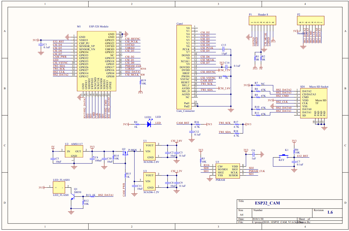
Schematic Diagram
ESP32-CAM AI-Thinker Pinout
The following diagram shows the pinout of the ESP32-CAM AI-Thinker Module:
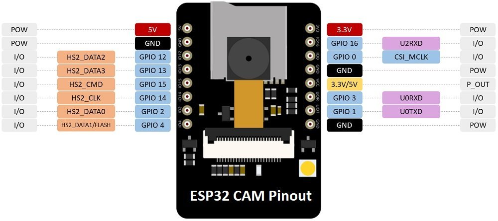
This section describes the pinout of the ESP32-CAM AI-Thinker Module. The ESP32-S chip has a total of 34 pins but only 16 pins are exposed to the pinout headers.
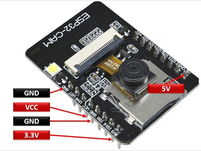
Power pins
The module has three ground pins and two positive power supply pins such as 5V and 3.3V pins. These pins can be used to power the ESP32-CAM AI-Thinker module. But it is recommended not to power this development bord with 3.3V pin, it does not provide stable power to board.
Power Output Pin
ESP32-CAM also provide one power output pin as shown in yellow color in the pinout diagram above. This is a VCC pin that can output either 5V or 3.3V. According to Jumper connection on ESP32-CAM, VCC pin provides 3.3V output.
GPIO33 – Built-in Red LED
AI-Thinker board also has one onboard RED LED. You can find this LED next to the reset button. This built-in red LED is connected with GPIO 33 in logic low active state. That means if we want to turn on LED, we drive GPIO 33 to logic low level. Similarly, to turn off LED, we drive GPIO 33 to active high state.

UART pins
Almost all the GPIO pins of ESP32-CAM are multi-purpose pins. GPIO1 and GPIO3 has alternate functions for the serial transmission and reception of the data for UART port, respectively. AI-Thinker board does not come with onboard programmer. Therefore, these UART pins are used to program and communicate with the PC to upload the code.
| Pin Name | Function |
|---|---|
| GPIO1 | U0TXD (UART Transmission pin) |
| GPIO3 | UORXD (UART Reception pin) |
We can use an FTDI cable to flash code to ESP32-CAM by using UART pins. You can read this article on how to use USB to serial FTDI cable:
GPIO0 pin – Flash Mode Selection
This pin determines the mode of the module such as flash or normal mode. In flashing mode, GPIO0 is pulled low which means it should be connected to the ground. When GPIO0 is connected to ground, ESP32-CAM goes into flashing mode and we can flash the code. After flashing the code to board, we should disconnect the GPIO0 from the ground to run the module normally or we say it enters the normal mode.
- GPIO0 connected to ground à ESP32-CAM in Flash Mode
- GPIO0 not connected to ground à ESP32-CAM in normal program execution mode
SD Card pins
As discussed in the previous section, ES32-CAM board has built-in SD card connector which can used to connect an SD card. These GPIO pins use for connections with micro SD cards while reading and writing data to SD card. These GPIO pins can be used as typical I/O pins if the SD card is not in use.
| Pin Name | SD Card Connection |
|---|---|
| GPIO2 | Data0 pin(RTC & ADC supported) |
| GPIO4/Flash lamp | Data1 pin(RTC & ADC supported) |
| GPIO12 | Data2 pin(RTC & ADC supported) |
| GPIO13 | Data3 pin(RTC & ADC supported) |
| GPIO14 | CLK(RTC & ADC supported) |
| GPIO15 | CMD(RTC & ADC supported) |
Note: If you are not using SD card in your ESP32-CAM project, you can use these GPIO pins for other functions such as digital input, digital output, ADC, and RTC.
You can find more features of these pins in the following article:
Flash LED pin
ESP32-CAM also has built-in high brightness flashlight. This flashlight can be used with a Camera while taking picture in darkness. GPIO4 is connected to an embedded flash lamp which (if programmed so) flashes when the camera captures the pictures. GPIO4 is also connected to the SD card, so it might cause difficulty accessing both at the same time. That means flashlight may glow unwanted while using SD card.

If you want to stop the flashlight from lighting up when using SD card, you can instruct the program to do not use GPIO4 as a data line for SD card by using this line:
SD_MMC.begin("/sdcard", true)Camera Connector Pins
The following table lists the GPIO pins connections with OV2640 Camera and their respective variable names that we will use in our program.
| OV2640 CAMERA | ESP32 | Variable name in code |
|---|---|---|
| D0 | GPIO5 | Y2_GPIO_NUM |
| D1 | GPIO18 | Y3_GPIO_NUM |
| D2 | GPIO19 | Y4_GPIO_NUM |
| D3 | GPIO21 | Y5_GPIO_NUM |
| D4 | GPIO36 | Y6_GPIO_NUM |
| D5 | GPIO39 | Y7_GPIO_NUM |
| D6 | GPIO34 | Y8_GPIO_NUM |
| D7 | GPIO35 | Y9_GPIO_NUM |
| XCLK | GPIO0 | XCLK_GPIO_NUM |
| PCLK | GPIO22 | PCLK_GPIO_NUM |
| VSYNC | GPIO25 | VSYNC_GPIO_NUM |
| HREF | GPIO23 | HREF_GPIO_NUM |
| SDA | GPIO 26 | SIOD_GPIO_NUM |
| SCL | GPIO 27 | SIOC_GPIO_NUM |
| POWER PIN | GPIO 32 | PWDN_GPIO_NUM |
ESP32-CAM Features and Specifications
The technical details and specifications of this extremely handy module are listed below:
| Feature | Availability |
| Module | ESP32-CAM AI-Thinker |
| Processor | 32-bit LX6 |
| Architecture | 7-stage pipeline |
| SPI Flash | 32-bit |
| SRAM | 520 KB |
| PSRAM | 4MB |
| Operating Temperature | -200C – 850C |
| Operating Voltage | 5 Volts |
| UART | 1 |
| UART Baud Rate | 115200 bps |
| SPI | Yes |
| I2C | Yes |
| PWM | Yes |
| Wi-fi | 802.11 b/g/n |
| Power Transmission | 802.11 b: 17±2 dBm at 11Mbps 802.11 g: 14±2 dBm at 54Mbps 802.11 n: 13±2 dBm at MCS7 |
| Bluetooth | Bluetooth 4.2 BR/EDR with BLE standards |
| Support TF Card | 4G Maximum Support |
| Security | WPA/WPA2/WPA2-Enterprise/WPS |
| Output Image Format | BMP, GRAYSCALE, JPEG(OV2640 support only) |
| Spectrum Range | 2412 MHz – 2484 MHz |
| On Board PCB Antenna Gain | 2dBi |
| Input/Output port | 9 |
| Reception Sensitivity | CCK, 1 Mbps: -90dBm CCK, 11 Mbps: -85dBm 6 Mbps (1/2 BPSK): -88dBm 54 Mbps (3/4 64-QAM): -70dBm MCS7 (65 Mbps, 72.2 Mbps): -67dBm |
| Power Dissipation | Turn off the flash: 180mA at 5V Turn on the flash with maximum brightness: 310mA at 5V Deep-sleep mode: the lowest power consumption can reach 6mA@5V Modem-sleep mode: < 20mA at 5V Light-sleep mode: <6.7mA at 5V |
| Clock Frequency | 240 MHz (max) |
| Package Type | DIP-16 |
| Package Size | 27*40.5*4.5(±0.2)mm |
Detailed Features
Some the additional prominent features of this amazing module are described as under:
- Supports Smart Config/AirKiss Technology and has capacitive GPIO pins.
- 18 high-resolution analog-to-digital converters.
- 2 digital-to-analog converters with a resolution power of 8-bits.
- Consumes power up to 600 DMIPS at 160 MHz of clock frequency.
- The module has high-speed WiFi with a speed of 2.4 GHz.
- ESP32 module contains 2 I2C, 3 SPI, and 3 UART for fast serial transmission.
- It also has 16 PWM channels to output pulse-width modulated signals.
- It has a TF holder and supports WiFi image upload.
- ESP32 supports 4 different operating modes i.e s STA/AP/STA+AP
- Embedded Lwip and FreeRTOS.
- RTC supported to wake up the module from Deep-sleep mode.
- A built-in flashlight is provided in the module to produce flashes to capture bright clear images.
- A CMOS technology IC has an adjustable output power amplifier
- ESP32 has a low duty cycle to reduce power consumption making it power efficient.
How to program ESP32-CAM AI-Thinker?
Unlike an ESP32 dev kit or other ESP32 development boards, the ESP32-CAM AI-Thinker board does not have any built-in programmer to burn the code to the ESP32-S chip. Therefore, to upload the code, we must use an external USB to UART Converter or an FTDI Programmer.
The following diagram shows the connection between ESP32-CAM and an FTDI cable. We use UART pins of ESP32-CAM to connect with an FTDI cable.

| ESP32-CAM | FTDI Cable |
|---|---|
| GND | GND |
| 5V | VCC (5V) |
| U0RX/GPIO3 | TX |
| U0TX/GPIO1 | RX |
| GPIO0 | GND |
In next tutorial, we will see how to install ESP32-CAM add-on in Arduino IDE and how to upload sample example code to AI-Thinker board using FTDI cable.
In Summary, in this tutorial, we learned the following:
- ESP32-CAM AI-Thinker Introduction, peripherals, and applications
- Pinout Diagram
- Power pins and Power Output Pin
- GPIO33 – Built-in Red LED
- UART pins
- GPIO0 pin – Flash Mode Selection
- SD Card pins
- Flash LED pin
- Camera Connector Pins
- How to program ESP32-CAM AI-Thinker?
In the coming tutorial, we will see how to create a web server with ESP32-CAM with live video streaming.
- ESP32-CAM Take Photo and Display in Web Server
- ESP32-CAM Capture Photo and Save to MicroSD Card
- ESP32-CAM Take and Send Photos via Email using an SMTP Server
- ESP32-CAM Capture and Save Photo to Firebase Storage
- ESP32-CAM Image Classification using Machine Learning
- ESP32-CAM Take Photo and Save to MicroSD Card with Timestamp Date and Time
Related ESP32 Tutorials:
Following on from this, does this mean that if a sd card AND external rtc is present, I could get away with using the rtc lines as long as I’m not actively reading /writing to the card at the time…..? In other words I want to use an external rtc to periodically wake up the esp32-cam, which will then do various things including access the card….. is that doable?
It is possible. But unfortunately, we do not have a tutorial available on this. But you can refer to this deep sleep tutorial of ESP32:
http://microcontrollerslab.com/micropython-esp32-deep-sleep-mode-wake-up-sources/
Gostaria de saber se é possível usar o Wifimanager ou o Autoconnect com o esp32-cam e se há já, algum código para isto? Obrigado
HI!
Thanks you this clear tutorial.
I want take photos and save in SD card withou flash.
You said: SD_MMC.begin(“/sdcard”, true)
Can you explain more or link to an example?
Thanks you very much.
Greetins
I will use this camera in a place where I can’t reach it easy.
So, I added some watchdogs:
* Check if WiFi is still active
* Check if ping is lower than 400ms
* Check if ping is higher than 0.1ms
When they fails I restart : ESP.restart();
But very often the camera was not found after the restart.
My first idea was to trigger a reset of the camera, but the ping CAM_RST is just connected to an power on reset circuit.
But the camera had a second internal power on reset check. The external PWDN (power down) will check if the power supply (CSI_2.8V and CSI1.2V) are high enough.
This pin is also not reachable from GIOP. But this can be triggered when the power supply (CSI_xx) went down.
The GIOP32 drives Q2 which powers the CSI voltage regulators.
To switch off the CSI voltage, just set the GOIP32 to High: digitalWrite(32,HIGH);
After doing this the ESP.restart(); will done.
Since using this, the camera module always come back.
Comments are welcome.
See below the code.
#include
float last_time_ms=0;
float avg_time_ms=0;
int WifiCount=0;
bool ret;
void setup() {
pinMode(33, OUTPUT); //Rote LED
pinMode(4, OUTPUT); //Blitzlicht
pinMode(32, OUTPUT); //Camera Power
//..
void loop() {
digitalWrite(33,LOW);
delay(1000);
digitalWrite(33,HIGH);
delay(1000);
if (WiFi.status()!= WL_CONNECTED){
Serial.println(“Reboot because of lost WiFi”);
digitalWrite(32,HIGH);
ESP.restart();
}
ret = Ping.ping(gateway);
avg_time_ms = Ping.averageTime();
if ((avg_time_ms+last_time_ms)>400) {
Serial.println(“Reboot because of high Ping”);
Serial.println(avg_time_ms);
digitalWrite(32,HIGH);
ESP.restart();
}
if (avg_time_ms>last_time_ms) {
last_time_ms = avg_time_ms;
Serial.println(avg_time_ms);
}
if (avg_time_ms <=0.10) {
Serial.println("Reboot because of low Ping");
digitalWrite(32,HIGH);
ESP.restart();
}
}
I make a face recognition system using the esp32-cam web server. Each enrolled faces will be have their own face id which are consist of 1,2,3,4 and so on. I save the face id in a variable called FACE_ID. Is it possible for me to send the variable value to esp8266 via serial communication or wifi server?
I notice in your wiring diagram, the FTDI has ground connected to the pin beside GPIO1. On new model ESP32 CAM this pin is NOT ground. It is connected to the ESP EN pin for ‘reset’ function. Best to use one of the other ‘GND’ pins.
The GPIO 12 and 13 can be used simultaneously with the SD card, it is simply necessary that the sd card must be used on 1 bits so just D0 and not from D0 to D3, the transfer times are also quite correct in this mode. If you want to make it an effective motion detector that sends you a smartphone notification there is the pycameresp project, which works perfectly well and is very reliable.
is there any way to change the framware of this esp32-cam by ai thinker to micropython, so that i can access the camera
I have a ESP32 Cam board and have coding working to take a photo and sent that photo to my email. This along with a home made weather station will be place up at our remote cabin in the mountains. We have only solar power and during the winter, snow can cover the solar panels for weeks. We have code that will turn on a relay twice a day which will turn on Starlink. Power to the ESP32 Cam will be turned on long enough for it to connect to wifi and send mail and then shut off again. The problem I am having is that the ESP32 CAM will not execute its code when it receives power reliably. Sometimes it does, most of the time it does not. I have connected to several different power sources, which I know are good power.
One this I have noticed is if I unplug the USB cable from power and then plug it back in, it always runs the code. I have read that on ESP32’s if a capacitor is added to the EN and GND pins, it will run the code when powered up. I am unable to find information which pin is the EN pin on the ESP32 Cam. Or is there another solution. Thank you.
The issue you’re experiencing is a known problem with ESP32 boards, including the ESP32-CAM, where the device doesn’t reliably boot when power is applied. This is often due to unstable power or the reset circuitry not initializing properly on power-up.
Potential Solutions
1. Add a Capacitor Between EN and GND
The EN pin (Enable) on the ESP32-CAM is usually labeled as EN or sometimes IO0 depending on the breakout board.
You can try adding a capacitor (typically 10 µF to 47 µF) between the EN pin and GND. This capacitor will help stabilize the signal on the EN pin during power-up.
To locate the EN pin:
Look for the EN pin on your ESP32-CAM board (usually near the middle or one of the corners).
If you’re unsure, consult the datasheet or pinout diagram for your specific ESP32-CAM board.
Solder the capacitor carefully, ensuring no short circuits.
2. Use a Resistor Between EN and GND
If adding a capacitor alone doesn’t work, add a 10 kΩ resistor between the EN pin and GND. This ensures the EN pin pulls low during power-on, resetting the chip correctly.
3. Power-On Reset Circuit
Build a simple power-on reset circuit using a capacitor and a pull-up resistor:
Connect a capacitor (~10 µF) between the EN pin and GND.
Connect a pull-up resistor (10 kΩ) between the EN pin and 3.3V.
This circuit delays the signal on the EN pin slightly, allowing the power to stabilize before the ESP32 initializes.
4. Ensure Stable Power Supply
Even though you mentioned trying multiple power sources, ensure that the ESP32-CAM is receiving clean and stable 5V.
The ESP32-CAM is particularly sensitive to voltage dips. Consider using a capacitor (e.g., 470 µF or larger) across the 5V and GND pins to help buffer power during startup.