This tutorial will focus on ESP32-CAM getting started guide. We will learn about ESP32-CAM by creating a live streaming application and face recognition example. Additionally, we will create a video streaming web server that will be used as a facial/object recognition tool using Arduino IDE.
You can know more about ESP32-CAM and its pinout here:
Recommended Components
The following components are used in this project or are helpful for building it with the ESP32.
| Component | How it’s used in this project | Buy on Amazon |
|---|---|---|
| ESP32 Development Board (DevKit V1) | The main controller that runs the project code and connects to the components. | Check Price |
| Micro USB Cable | Connects the ESP32 to your computer for programming and power. | Check Price |
| Breadboard | Lets you build the circuit and wire up parts without soldering. | Check Price |
| Jumper Wires | Make the connections between the ESP32 and the components on the breadboard. | Check Price |
| ESP32-CAM board | Camera board that captures and streams video for face recognition. | Check Price |
| FTDI / USB-TTL programmer | Uploads the sketch to the ESP32-CAM, which has no built-in USB. | Check Price |
As an Amazon Associate we earn from qualifying purchases. Prices and availability are accurate as of the date/time indicated and are subject to change.
Prerequisites
We will use Arduino IDE to program our ESP32 development boards. Thus, you should have the latest version of Arduino IDE. Additionally, you also need to install the ESP32 plugin. If your IDE does not have the plugin installed you can visit the link below:
Installing ESP32 library in Arduino IDE and upload code.
Required Hardware:
- ESP32-CAM module
- FTDI programmer
ESP32-CAM Introduction
The ESP32-CAM development board is another member of the ESP32 module family. It is an inexpensive board consisting of an ESP32-S chip, an OV2640 video camera, and a micro-SD card slot that is extremely useful in major IoT applications. It can be used with advanced projects where facial recognition, image tracking, wireless monitoring, and identification are required.
Key Features of ESP32-CAM module
The ESP32-CAM consists of the ESP32 chip so it shares the same specifications as that of the generic ESP32 module. The key features of the ESP32-CAM module are given below:
- 802.11b/g/n Wi-Fi, Classic Bluetooth 4.2 and BLE
- Consists of two 32-bit LX6 CPUs
- Has 7 stage pipeline architecture
- Equipped with Hall, on-chip and temperature sensor
- Main frequency ranges from 80MHz-240MHz
- Supports UART/SPI/I2C/PWM/ADC/DAC interfaces
- 520 KB SRAM and 4MB PSRAM
- 160MHz clock speed with computing power up to 600 DMIPS
- Supports OV2640/OV7670 video cameras with built-in flash, image Wi-Fi upload, TF card, FOTA upgrades and various sleep modes
- FreeRTOS and embedded Lwip
ESP32-CAM OV2640 Video Camera Specifications
As mentioned before, the ESP32-CAM module consists of an OV2640 camera module. It has the following specifications:
- 2 Megapixel sensor
- UXGA 1622×1200
- Output formats include: YUV422, YUV420, RGB565, RGB555
- 15-60 fps image transfer rate
ESP32-CAM Pinout
The diagram below shows the pinout of the ESP32-CAM module. It is taken from a datasheet which can be accessed from here. Notice that this module has a lesser number of GPIO pins than the ESP32 development board we have been previously using. This is because various pins are used internally for the camera and micro-SD card slot.
Recommended Reading: ESP32-CAM AI-Thinker Board – All about GPIO Pins
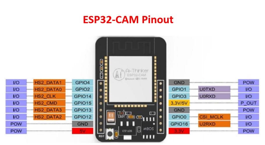
Note: You need to connect GPIO0 with the GND pin to enable the module to go in flashing mode. Before uploading your code, make sure the GPIO0 is grounded.
Front and Back side of ESP32-CAM Module
The diagram below shows the front of the ESP32-CAM module:
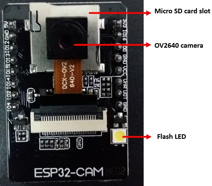
As you see the front side of the board has the camera module and the micro-SD card slot. You can also view the in-built flash LED which is useful when taking images.
The diagram below shows the bask side of the ESP32-CAM module:
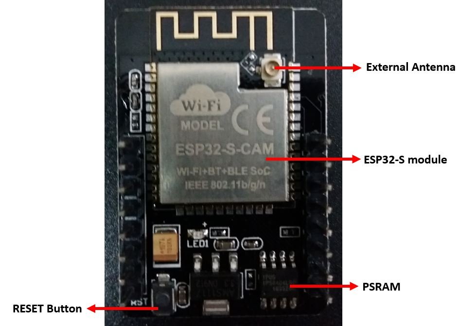
As you can see, this side consists of the ESP32-S chip, a connector for an external antenna, and also an internal antenna. You can also view the RESET button and the PSRAM.
Connecting ESP32-CAM with FTDI programmer
Unlike the ESP32 development board, the ESP32-CAM does not come with the USB port attached to it. So to upload a program sketch to the ESP32-CAM, we will need to use an FTDI programmer (USB to TTL Serial converter).
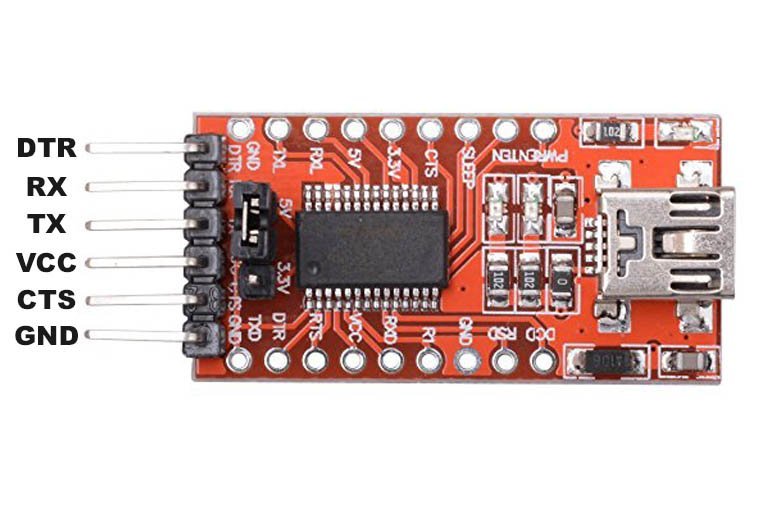
You can learn more about this FTDI cable here:
The table shows the connections between the ESP32-CAM and FTDI programmer:
| ESP32-CAM | FTDI Programmer |
|---|---|
| 3.3V | VCC |
| UOR (GPIO3) | TX |
| UOT (GPIO1) | RX |
| GND | GND |
The diagram below shows how to connect ESP32-CAM with the FTDI programmer.
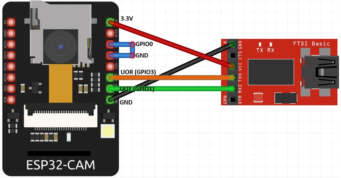
Connect the 3.3V pin of ESP32-CAM with the VCC pin of the FTDI programmer to power up. Both grounds of the two devices will be connected in common. The TX pin of the FTDI programmer will be connected with UOR (GPIO3) of ESP32-CAM. Likewise, the RX pin will be connected with the UOT (GPIO1) of the ESP32-CAM module.
Additionally, you will need to connect GPIO0 with GND to enable the ESP32-CAM module to go in flashing mode. Remove this connection after uploading the program sketch to the module.
On some ESP32-CAM boards, you will get a brown-out detector error which is due to the insufficient voltage provided by the FTDI cable. In that case, you should connect an external 5V power supply to ESP32 as shown below:

Video Streaming Web Server Example Sketch
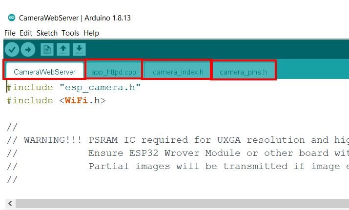
After having some insight regarding the ESP32-CAM module let us proceed with a simple example to see it in action. We will use the example sketch from our Arduino IDE for ESP32. Open your Arduino IDE and go to Files > Examples > ESP32 > Camera > CameraWebServer.

The following sketches will open up.
#include "esp_camera.h"
#include <WiFi.h>

//
// WARNING!!! PSRAM IC required for UXGA resolution and high JPEG quality
//            Ensure ESP32 Wrover Module or other board with PSRAM is selected
//            Partial images will be transmitted if image exceeds buffer size
//

// Select camera model
#define CAMERA_MODEL_WROVER_KIT // Has PSRAM
//#define CAMERA_MODEL_ESP_EYE // Has PSRAM
//#define CAMERA_MODEL_M5STACK_PSRAM // Has PSRAM
//#define CAMERA_MODEL_M5STACK_V2_PSRAM // M5Camera version B Has PSRAM
//#define CAMERA_MODEL_M5STACK_WIDE // Has PSRAM
//#define CAMERA_MODEL_M5STACK_ESP32CAM // No PSRAM
#define CAMERA_MODEL_AI_THINKER // Has PSRAM
//#define CAMERA_MODEL_TTGO_T_JOURNAL // No PSRAM

#include "camera_pins.h"

const char* ssid = "*********";
const char* password = "*********";

void startCameraServer();

void setup() {
  Serial.begin(115200);
  Serial.setDebugOutput(true);
  Serial.println();

  camera_config_t config;
  config.ledc_channel = LEDC_CHANNEL_0;
  config.ledc_timer = LEDC_TIMER_0;
  config.pin_d0 = Y2_GPIO_NUM;
  config.pin_d1 = Y3_GPIO_NUM;
  config.pin_d2 = Y4_GPIO_NUM;
  config.pin_d3 = Y5_GPIO_NUM;
  config.pin_d4 = Y6_GPIO_NUM;
  config.pin_d5 = Y7_GPIO_NUM;
  config.pin_d6 = Y8_GPIO_NUM;
  config.pin_d7 = Y9_GPIO_NUM;
  config.pin_xclk = XCLK_GPIO_NUM;
  config.pin_pclk = PCLK_GPIO_NUM;
  config.pin_vsync = VSYNC_GPIO_NUM;
  config.pin_href = HREF_GPIO_NUM;
  config.pin_sscb_sda = SIOD_GPIO_NUM;
  config.pin_sscb_scl = SIOC_GPIO_NUM;
  config.pin_pwdn = PWDN_GPIO_NUM;
  config.pin_reset = RESET_GPIO_NUM;
  config.xclk_freq_hz = 20000000;
  config.pixel_format = PIXFORMAT_JPEG;

  // if PSRAM IC present, init with UXGA resolution and higher JPEG quality
  //                      for larger pre-allocated frame buffer.
  if(psramFound()){
    config.frame_size = FRAMESIZE_UXGA;
    config.jpeg_quality = 10;
    config.fb_count = 2;
  } else {
    config.frame_size = FRAMESIZE_SVGA;
    config.jpeg_quality = 12;
    config.fb_count = 1;
  }

#if defined(CAMERA_MODEL_ESP_EYE)
  pinMode(13, INPUT_PULLUP);
  pinMode(14, INPUT_PULLUP);
#endif

  // camera init
  esp_err_t err = esp_camera_init(&config);
  if (err != ESP_OK) {
    Serial.printf("Camera init failed with error 0x%x", err);
    return;
  }

  sensor_t * s = esp_camera_sensor_get();
  // initial sensors are flipped vertically and colors are a bit saturated
  if (s->id.PID == OV3660_PID) {
    s->set_vflip(s, 1); // flip it back
    s->set_brightness(s, 1); // up the brightness just a bit
    s->set_saturation(s, -2); // lower the saturation
  }
  // drop down frame size for higher initial frame rate
  s->set_framesize(s, FRAMESIZE_QVGA);

#if defined(CAMERA_MODEL_M5STACK_WIDE) || defined(CAMERA_MODEL_M5STACK_ESP32CAM)
  s->set_vflip(s, 1);
  s->set_hmirror(s, 1);
#endif

  WiFi.begin(ssid, password);

  while (WiFi.status() != WL_CONNECTED) {
    delay(500);
    Serial.print(".");
  }
  Serial.println("");
  Serial.println("WiFi connected");

  startCameraServer();

  Serial.print("Camera Ready! Use 'http://");
  Serial.print(WiFi.localIP());
  Serial.println("' to connect");
}

void loop() {
  // put your main code here, to run repeatedly:
  delay(10000);
}
We will have to make some changes to the sketch before uploading it to our module. First, inside the CameraWebServer go to “Select Camera Mode” and uncomment the particular model which you are using for the ESP32-CAM. In our case, it is the ESP32 AI thinker module.
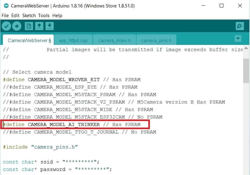
// Select camera model
//define CAMERA_MODEL_WROVER_KIT // Has PSRAM
//#define CAMERA_MODEL_ESP_EYE // Has PSRAM
//#define CAMERA_MODEL_M5STACK_PSRAM // Has PSRAM
//#define CAMERA_MODEL_M5STACK_V2_PSRAM // M5Camera version B Has PSRAM
//#define CAMERA_MODEL_M5STACK_WIDE // Has PSRAM
//#define CAMERA_MODEL_M5STACK_ESP32CAM // No PSRAM
#define CAMERA_MODEL_AI_THINKER // Has PSRAM
//#define CAMERA_MODEL_TTGO_T_JOURNAL // No PSRAM
Next, enter your network credentials to connect with Wi-Fi in the global variables ssid and password.
const char* ssid = "*********";
const char* password = "*********";
Uploading and demonstration
Now, we are ready to compile and upload the code to our ESP32-CAM. Make sure the FTDI programmer is properly connected with the module and GPIO0 is grounded as well.
Choose the correct board and COM port before uploading your code to the ESP32-CAM board. Go to Tools > Board and select ESP32 AI Thinker.
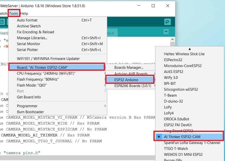
Next, go to Tools > Port and select the appropriate port through which your board is connected.
Click on the upload button to upload the code into the ESP32 board.
After you have uploaded your code to the board, remove the connecting wire from GPIO0 and GND.
Now open the serial monitor and press the RESET button on the ESP32-CAM.

You will be able to view the following messages including the IP address:
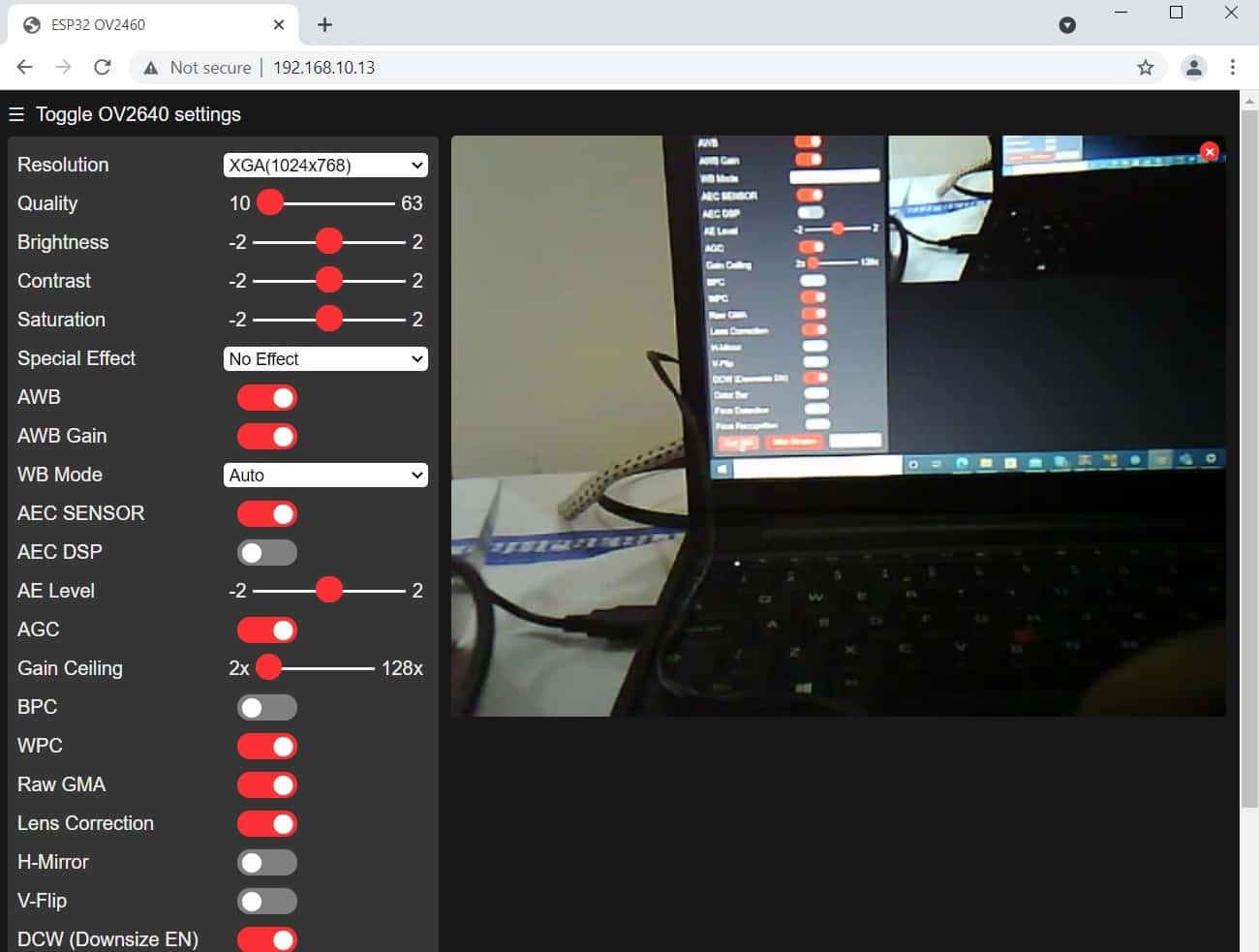
Open a new web browser. Type the IP address in the search bar and press enter. The video streaming web server will open. Press the ‘Start Stream’ button found at the bottom of the web page to start the video streaming.
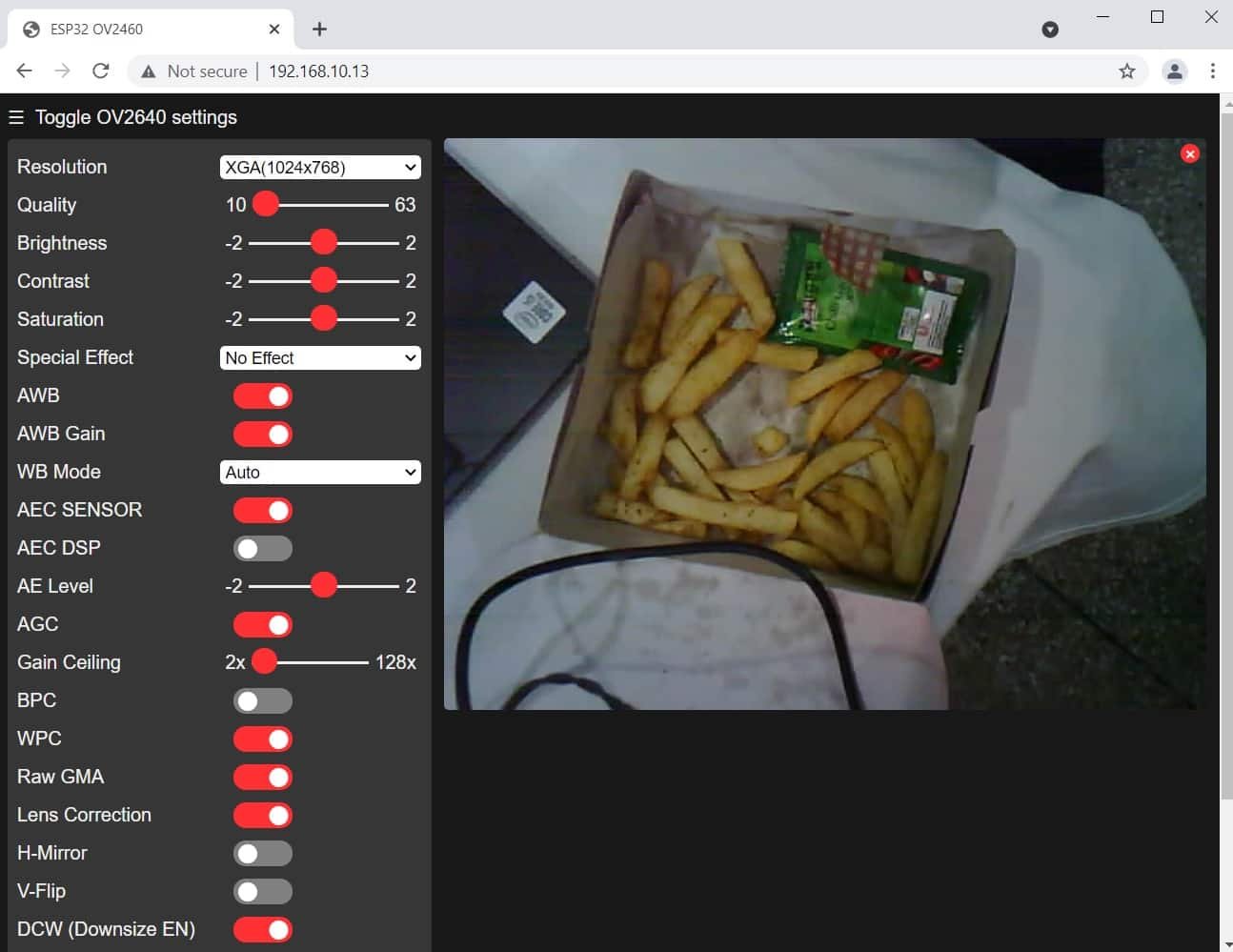
As you can see there are several options to choose from. Check the ‘Face Recognition’ and ‘Face Detection’ option to enable the video streaming web server to act as a facial detection tool.
Now, we will have to save a face which will be detected. To add a face, select the option ‘Enroll Face.’ After the face is saved successfully, the web server will detect the person as ‘subject 0’ and anyone else as an intruder. This can act as a security system to detect and recognize people.
Conclusion
In conclusion, in this getting started ESP32-CAM guide we looked over the key features of this module. We have also learned how to use the ESP32-CAM through an example sketch where we used the face detection option to recognize people. This can be incorporated in advanced IoT applications easily to generate a security tool.
You may also like to read:
Good day! I follow your everything in this tutorial but unfortunately the esp32 cam can’t detect my face. Can you help me about this issue?