In this tutorial, we will learn to use ESP32 I2C communication channels using Arduino IDE. We will learn how to use different pins of ESP32 for I2C communication apart from the default I2C pins, connect different I2C devices to the same bus and also see how to use the two I2C bus interfaces. Moreover, we will interface ESP32 with different sensors and devices that communicate via I2C protocol and program our board to run an I2C scanner. This scanner will determine the number of I2C devices connected with the ESP32 board.
The ESP32 has two I2C bus interfaces that are used for I2C communication. The user can configure the ESP32 board as an I2C master or I2C slave.
Recommended Components
The following components are used in this project or are helpful for building it with the ESP32.
| Component | How it’s used in this project | Buy on Amazon |
|---|---|---|
| ESP32 Development Board | The I2C master board that communicates with the connected I2C devices. | Check Price |
| Micro USB Cable | Connects the ESP32 to your computer for programming and power. | Check Price |
| Breadboard | Lets you share the SDA and SCL bus among the I2C devices without soldering. | Check Price |
| Jumper Wires | Connect the SDA, SCL, power and ground lines between the ESP32 and the devices. | Check Price |
| 0.96″ SSD1306 OLED Display | One of the I2C slave devices used to demonstrate sharing the bus. | Check Price |
| BME280 | An I2C sensor read for temperature, pressure and humidity in the examples. | Check Price |
| MPU6050 | An I2C accelerometer and gyroscope used as a third device on the bus. | Check Price |
As an Amazon Associate we earn from qualifying purchases. Prices and availability are accurate as of the date/time indicated and are subject to change.
Prerequisite
We will use Arduino IDE to program our ESP32 development board. Thus, you should have the latest version of Arduino IDE. Additionally, you also need to install the ESP32 plugin.
If your IDE does not have the plugin installed you can visit the link below: Installing ESP32 library in Arduino IDE and upload code.
I2C Protocol Introduction
I2C is also known as an inter-integrated circuit or IIC or I square C. It is a 2-wire serial communication protocol for short-range data transfer applications. It is an asynchronous half-duplex serial communication protocol. Furthermore, it is a multi-master bus protocol that requires only two wires to transfer data serially which are SCL and SDA.
- SDA ( Bidirectional data line)
- SCL ( Bidirectional clock line)
It is a very popular communication protocol used in embedded projects to interface I2C based sensors, digit displays, and communication modules. Devices that want to communicate with each connect through an I2C bus. I2C bus supports multiple slave devices and multiple master devices.
Data is transferred bit by bit serially along a wire (the SDA line). Like SPI, I2C is concurrent, the output of bits is synchronized to the testing of bits by a clock signal shared between the master and the slave.
Many Sensors use this serial communication protocol to transfer their data to microcontrollers or through this protocol different slave circuits are able to communication with master circuits. It is only applicable for short distance data transmission.
I2C Pins
The distinguishing feature of I2C over SPI is that it uses only two wires to carry out communication. One wire is SCL (serial clock line) which synchronizes the transmission of data between devices and the other wire is SDA (serial data) which carries the actual data to be transmitted. These lines are open-drain lines which means these need to be connected to pull up resistors if devices are active low. Each slave device which is connected with the bus will have a unique 8-bit address.
Note: The SDA line is also known as SDI and the SCL line is also known as SCK.
The communication between specific devices using two wires is accomplished by the fact that each device has its own unique device ID or address and using this address; master can choose any specific device to communicate.
For example, we can connect multiple slaves to one master. The ESP32 is configured as a master device and multiple slave devices are connected with the same bus.

We can also connect multiple masters controlling the same slave. For example, two ESP32 boards configured as master devices connected with the same slave device.
I2C Bus
I2C bus consists of multiple devices such as slave and master devices. Each device connected with the I2C bus can be either in master mode or in slave mode. But only a master device can initiate the data transfer process. Usually, there is one master and one slave or multiple slave devices connected with the same I2C bus through pull-up resistors. Each salve address has a 7-bit unique address.
Slave Devices
Each slave device has a unique address that is utilized to recognize the device on the bus. In other words, slave address helps the master device to send information to a
specific slave device on the bus.
Master devices
Master devices can send and get information. Slaves react to whatever a master sends. When sending information on the bus, just a single device can send information at a time.
In short, we only need two wires for transferring data or communicating with different numbers of devices. I2C allows us to connect with multiple devices at the same time. However, you cannot use this protocol for long-distance data transferring.
For more information on I2C Communication, you can read this post:
ESP32 I2C Pins
As mentioned earlier ESP32 has 2 I2C controllers which can be used to handle communication on an I2C bus. We can configure either as a master or slave. Now let’s see the default GPIO pins which are assigned to I2C controllers in the Arduino IDE library for ESP32.
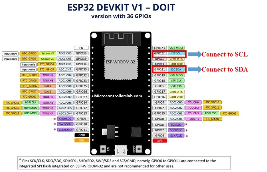
The default I2C pin in ESP32 for SDA is GPIO21 and for SCL is GPIO22. If we want to change the GPIO pins we have to set them in code. The diagram below shows the pinout for the ESP32 which shows the default I2C pins.
The ESP32 I2C interface has the following features:
- Standard mode (100 Kbit/s)
- Fast mode (400 Kbit/s)
- Up to 5 MHz, yet constrained by SDA pull-up strength
- 7-bit/10-bit addressing mode
- Dual addressing mode
Using Multiple Slave I2C Devices with ESP32 (I2C devices with different addresses)
In this section, we will first connect three different I2C devices with the ESP32 board using the default I2C pins. Then we will program our board to run an I2C scanner.
Components Required
- ESP32 development board
- SSD1306 OLED Display
- BME280 sensor
- MPU6050 sensor
- Breadboard
- Connecting Wires
First let us briefly introduce the three I2C devices that we will use in this guide: SSD1306 OLED, BME280, and MPU6050.
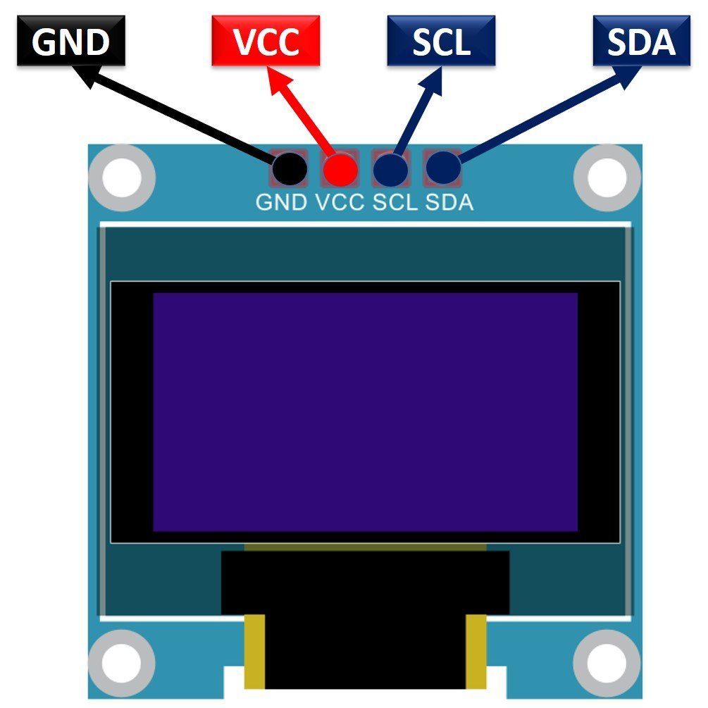
SSD1306 0.96inch OLED Display
Although there are several types of OLED displays available in the market the one which we will be using is the SSD1306 0.96-inch OLED display. The main component of all different types of OLED displays is an SSD1306 controller which uses I2C or SPI protocol to communicate with the microcontrollers. The OLED displays can vary in size, color, and shape but primarily programmed in a similar way.
Let us take a look at the OLED display which we will be using in this article. It is called SSD 1306 0.96-inch OLED display which has 128×64 pixels and communicates only via I2C protocol with the Pi Pico board. It is cheap and readily available in the market.
BME280
The BME280 sensor is used to measure readings regarding ambient temperature, barometric pressure, and relative humidity. It is mostly used in web and mobile applications where low power consumption is key. This sensor uses I2C or SPI to communicate data with the micro-controllers. Although there are several different versions of BME280 available in the market, the one we will be studying uses I2C communication protocol.

The ESP32 communicates with the BME280 sensor through the I2C protocol to give temperature, barometric pressure, and relative humidity readings.
MPU6050 Sensor Module
The MPU6050 sensor module is a MEMS( Micro-Electro-Mechanical System) module that contains an integrated circuit MPU6050 IC. This chip contains a three-axis gyroscope, three-axis accelerometer, and digital motion control processor within a single IC package. On top of that, it also contains an integrated temperature sensor.
MPU6050 provides output data on an I2C bus. Therefore, we can use an I2C bus interface of MPU6050 to transfer a 3-axis accelerometer and 3-axis gyroscope values to Raspberry Pi Pico. In other words, we can use any microcontroller which has an I2C port to read sensors’ output data. There is a specific dedicated address assigned to each parameter value in the MPU6050 I2C interface. We can use these addresses to get specific values from a sensor such as acceleration, gyro, and temperature.
One of the advantages of using the I2C interface of this sensor is that we can interface multiple MPU5060 modules with a single microcontroller.

Interface ESP32 with OLED, BME280 and MPU6050
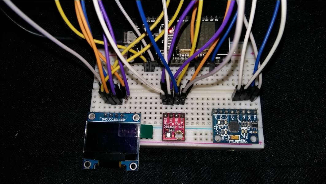
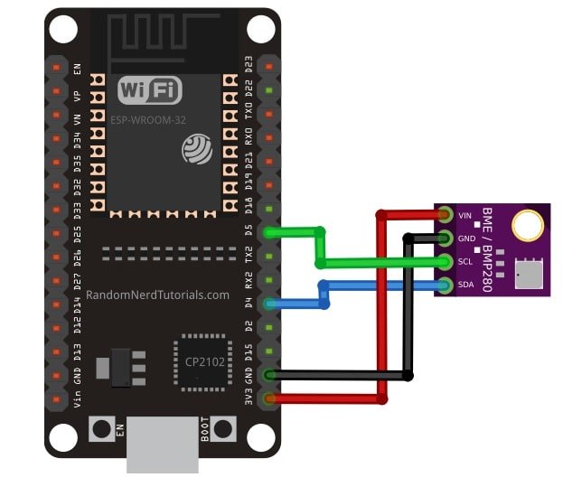
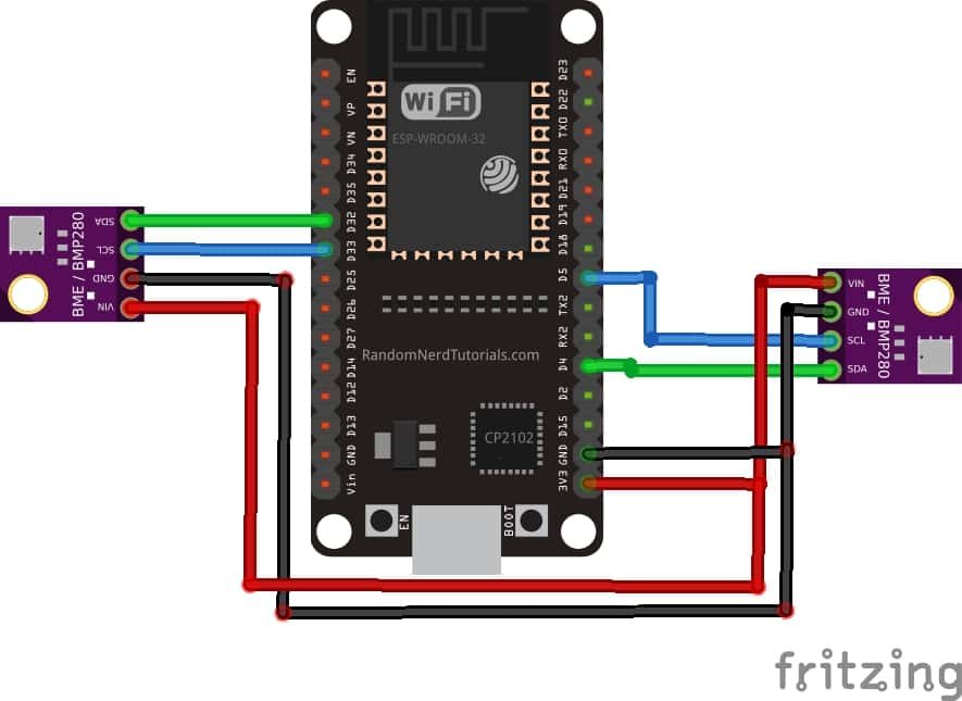
Let us see how to connect ESP32 with an OLED, BME280 module, and MPU6050 module together. We will use a common I2C line to connect all the devices. The ESP32 will act as a master, and the BME280 sensor, MPU6050 sensor, and the OLED will act as slaves.
The connections between the four devices which we are using can be seen in the table below.
| ESP32 | SSD1306 OLED Display | BME280 | MPU6050 |
| 3.3V | VCC | VCC | VCC |
| GPIO21(I2C SDA) | SDA | SDA | SDA |
| GPIO22 (I2C SCL) | SCL | SCL | SCL |
| GND | GND | GND | GND |
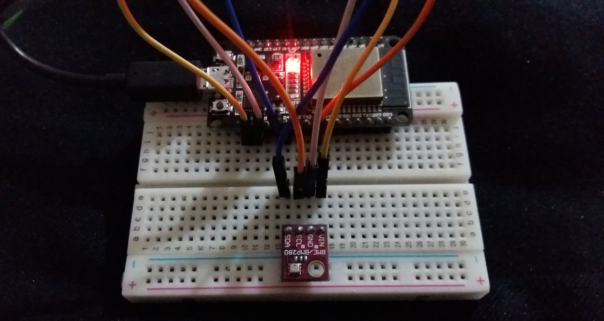
We have used the same connections as specified in the table above.

ESP32 I2C Scanner Arduino Sketch
Every I2C device has an address associated with it. The ESP32 uses this address to communicate with the slave via I2C protocol.
Now copy this code and upload it your board with all the I2C devices already connected with it.
This code will scan for any I2C devices connected with ESP32 and will specify the number of devices with the address in the serial terminal.
#include <Wire.h>

void setup() {
  Wire.begin();
  Serial.begin(115200);
  Serial.println("\nI2C Scanner");
    byte error, address;
  int nDevices;
  Serial.println("Scanning...");
  nDevices = 0;
  for(address = 1; address < 127; address++ ) {
    Wire.beginTransmission(address);
    error = Wire.endTransmission();
    if (error == 0) {
      Serial.print("I2C device found at address 0x");
      if (address<16) {
        Serial.print("0");
      }
      Serial.println(address,HEX);
      nDevices++;
    }
    else if (error==4) {
      Serial.print("Unknown error at address 0x");
      if (address<16) {
        Serial.print("0");
      }
      Serial.println(address,HEX);
    }
  }
  if (nDevices == 0) {
    Serial.println("No I2C devices found\n");
  }
  else {
    Serial.println("done\n");
  }
  delay(5000);
  Serial.print("i2c devices found:");
  Serial.println(nDevices);
}

void loop() {

}

The I2C scanner identified 3 devices connected to the I2C interface. The I2C Address of OLED Display is 0x3C, MPU6050 is 0x68, BME280 is 0x76.
As all of these three I2C devices had different addresses therefore it was possible to share the same I2C bus.
Using Multiple I2C Devices with ESP32 same addresses
In the previous section, we were able to connect three different I2C devices on the same I2C pins of ESP32. This was because the ESP32 was able to identify them due to their unique address. However, what happens when we want to connect multiple devices with ESP32 for I2C communication but they have the same address? For example, two BME280 sensors connected with ESP32 or two OLEDs connected with ESP32.
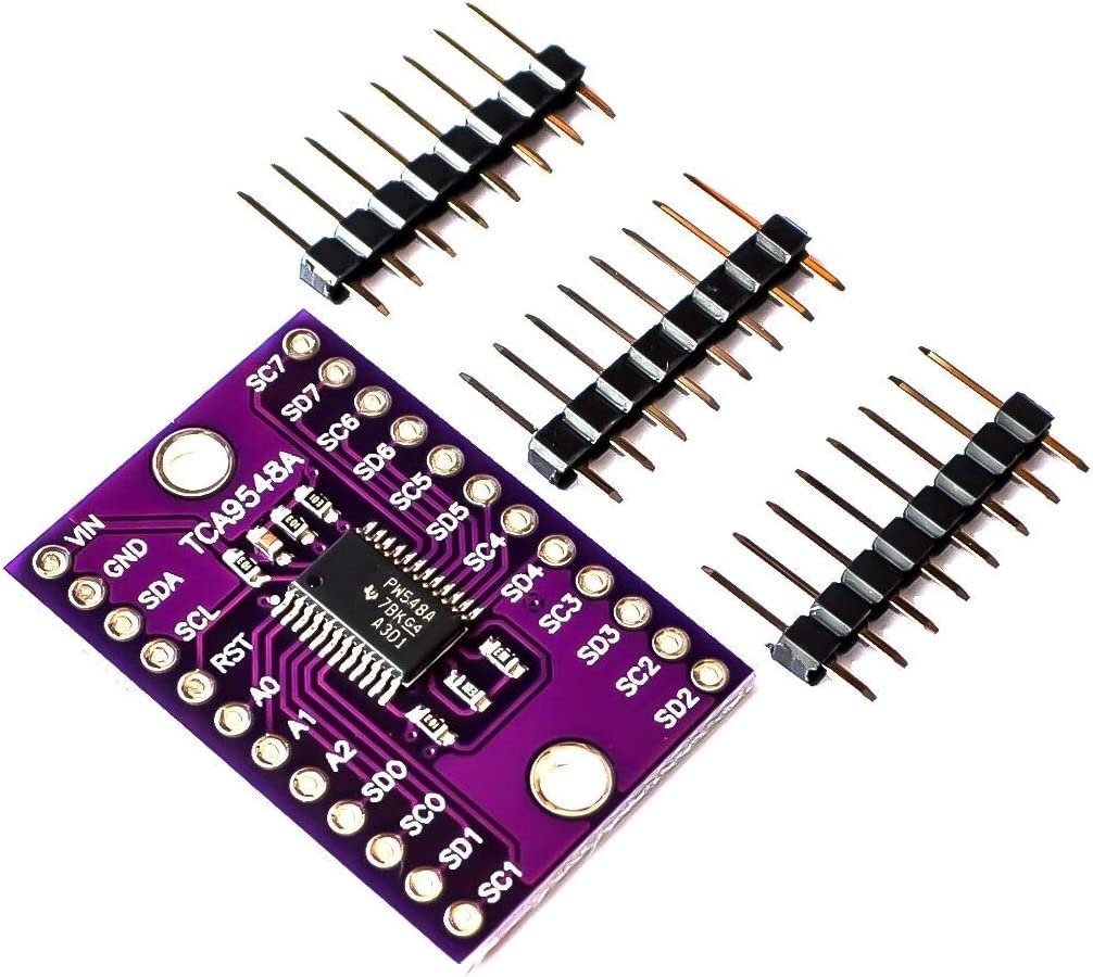
To use the same I2C devices with the ESP32 board, we would either have to change the I2C address of the device or use an I2C multiplexer. However, it is not that simple to change the address of a device and it only allows limited devices to be used on the same I2C bus. Hence we can use a multiplexer eg. TCA9548A that will allow a maximum of eight devices with the same addresses to be connected to the same I2C bus.
Change ESP32 default I2C pins in Arduino IDE
As we mentioned before, the default I2C pin in ESP32 for SDA is GPIO21 and for SCL is GPIO22. If we want to change the default I2C pins we have to set them in code. Most of the GPIO pins of ESP32 can be set as I2C pins.
The Wire.h library is used in Arduino IDE to communicate with I2C devices. It uses the begin() method on the Wire instance to initialize the protocol. If we do not specify any parameters inside this function, then default I2C SDA and SCL pins are used.
Wire.begin();If however, we want to change the default I2C pins then we specify them as parameters inside the function. Wire.begin() takes in two parameters. The first is the I2C SDA pin and the second is the I2C SCL pin that we want to configure
Wire.begin(I2C_SDA, I2C_SCL);Communications through Libraries
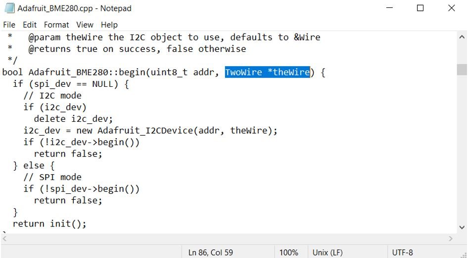
Sometimes libraries are involved to establish communication between the master and the slave. For example, to communicate with BME280 sensor, we require Adafruit BME280 library. The above method will not work in this case because a library is involved to establish communication between the sensor and the ESP32 board. Therefore, if you want to use different I2C pins for such sensors, then we should first refer to the .cpp file of the library and carefully analyze the TwoWire parameters. In case, the library files contain wire.begin(), then you will have to comment it out first in order to set your own I2C pins.
Lets demonstrate this with the BME280 sensor with ESP32. Open Adafruit_BME.cpp and head over to the definition of the begin() method. Here you can view that we have an option to pass our own TwoWire to this method.
Change I2C Pins with BME280
In this example, we use GPIO4 as SDA and GPIO5 as SCL to obtain the BME280 sensor readings with ESP32.
Arduino Sketch
The Arduino sketch below uses GPIO4 as SDA and GPIO5 as SCL to obtain the BME280 sensor readings.
#include <Wire.h>
#include <Adafruit_Sensor.h>
#include <Adafruit_BME280.h>

#define I2C_SDA 4
#define I2C_SCL 5

#define SEALEVELPRESSURE_HPA (1013.25)

TwoWire I2CBME = TwoWire(0);
Adafruit_BME280 bme;

void setup() {
  Serial.begin(115200);
  I2CBME.begin(I2C_SDA, I2C_SCL, 100000ul);

  bool status;
  status = bme.begin(0x76, &I2CBME);
  if (!status) {
    Serial.println("Could not find a valid BME280 sensor, check wiring!");
    while (1);
  }
  delay(1000);
  Serial.println();
}

void loop() {
  Serial.print("Temperature = ");
  Serial.print(bme.readTemperature());
  Serial.println(" *C");

  Serial.print("Pressure = ");
  Serial.print(bme.readPressure() / 100.0F);
  Serial.println(" hPa");

  Serial.print("Altitude = ");
  Serial.print(bme.readAltitude(SEALEVELPRESSURE_HPA));
  Serial.println(" m");

  Serial.print("Humidity = ");
  Serial.print(bme.readHumidity());
  Serial.println(" %");

  Serial.println();
  delay(1000);
}
How the Code Works?
To use different I2C pins, we start by defining the I2C pins that we want to set for the SDA and SCL in their respective variables. In this example, we are using GPIO4 as SDA and GPIO5 as SCL.
#define I2C_SDA 4
#define I2C_SCL 5
Next, we will create a TwoWire instance called I2CBME for the I2C bus.
TwoWire I2CBME = TwoWire(0);Inside the setup() function, we will initialize the I2C communication by using the TwoWire instance on the begin() method. It takes in three parameters. The first parameter is the SDA pin that we previously defined. The second parameter is the SCL pin that we previously defined. The third parameter is the clock frequency.
I2CBME.begin(I2C_SDA, I2C_SCL, 100000ul);Next, we will initialize the BME object with the begin() method and specify the address of the BME280 sensor as the first parameter and the address of the TwoWire instance as the second parameter.
status = bme.begin(0x76, &I2CBME);To obtain the BME280 sensor readings we will use the respective methods on the bme object to acquire the temperature, pressure and humidity readings.
Serial.print("Temperature = ");
  Serial.print(bme.readTemperature());
  Serial.println(" *C");

  Serial.print("Pressure = ");
  Serial.print(bme.readPressure() / 100.0F);
  Serial.println(" hPa");

  Serial.print("Altitude = ");
  Serial.print(bme.readAltitude(SEALEVELPRESSURE_HPA));
  Serial.println(" m");

  Serial.print("Humidity = ");
  Serial.print(bme.readHumidity());
  Serial.println(" %");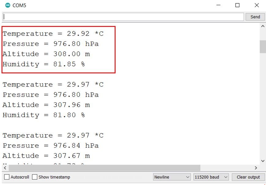
Using both I2C Bus Interfaces of ESP32
In all the previous examples before, we have been using only one I2C interface of the ESP32 board. However, ESP32 provides two I2C bus interfaces let us see some examples of how to use both of them as well. There are two methods to achieve this.
Arduino Sketch Example 1
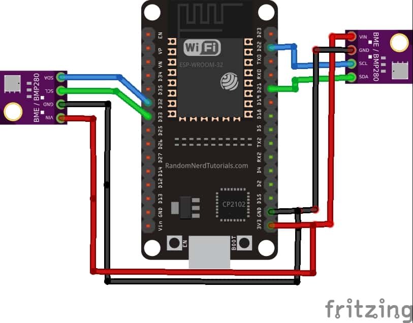
In this method, we will connect two BME280 sensors with ESP32 while using two I2C interfaces of ESP32. The first BME280 sensor will be connected with SDA GPIO4 and SCL GPIO5 and the second BME280 sensor will be connected with SDA GPIO33 and SCL GPIO32.
#include <Wire.h>
#include <Adafruit_Sensor.h>
#include <Adafruit_BME280.h>

#define SDA_1 4
#define SCL_1 5

#define SDA_2 33
#define SCL_2 32

TwoWire I2C_1 = TwoWire(0);
TwoWire I2C_2 = TwoWire(1);

Adafruit_BME280 bme1;
Adafruit_BME280 bme2;

void setup() {
  Serial.begin(115200);

  I2C_1.begin(SDA_1, SCL_1, 100000ul);
  I2C_2.begin(SDA_2, SCL_2, 100000ul);

  bool status1 = bme1.begin(0x76, &I2C_1);
  if (!status1) {
    Serial.println("Could not find a valid BME280_1 sensor, check wiring!");
    while (1);
  }

  bool status2 = bme2.begin(0x76, &I2C_2);
  if (!status2) {
    Serial.println("Could not find a valid BME280_2 sensor, check wiring!");
    while (1);
  }

  Serial.println();
}

void loop() {
  //bme1
  Serial.print("Temperature from BME1= ");
  Serial.print(bme1.readTemperature());
  Serial.println(" *C");

  Serial.print("Humidity from BME1 = ");
  Serial.print(bme1.readHumidity());
  Serial.println(" %");

  Serial.print("Pressure from BME1 = ");
  Serial.print(bme1.readPressure() / 100.0F);
  Serial.println(" hPa");

  Serial.println(" ");

  //bme2
  Serial.print("Temperature from BME2 = ");
  Serial.print(bme2.readTemperature());
  Serial.println(" *C");

  Serial.print("Humidity from BME2 = ");
  Serial.print(bme2.readHumidity());
  Serial.println(" %");

  Serial.print("Pressure from BME2 = ");
  Serial.print(bme2.readPressure() / 100.0F);
  Serial.println(" hPa");

  Serial.println(" ");
  delay(5000);
}
How does Code Work?
Define the I2C SDA and SCL pins for both the BME280 sensors. In this case, we are using GPIO4 for SDA and GPIO5 for SCL for the first sensor. Likewise, we are using GPIO33 for SDA and GPIO32 for SCL for the second sensor.
#define SDA_1 4
#define SCL_1 5

#define SDA_2 33
#define SCL_2 32
Next we will be required to create two TwoWire instances as compared to a single TwoWire instance for the two I2C bus interfaces.
TwoWire I2C_1 = TwoWire(0);
TwoWire I2C_2 = TwoWire(1)
Create two objects of Adafruit_BME280 called ‘bme1’ for the first sensor and ‘bme2’ for the second sensor. These will be used later on to access the sensor data.
Adafruit_BME280 bme1;
Adafruit_BME280 bme2;
Next, inside the setup() function we will initialize the I2C communication for both interfaces at the defined I2C pins and frequency.
void setup() {
  I2C_1.begin(SDA_1, SCL_1, frequency1);
  I2C_2.begin(SDA_2, SCL_2, frequency2);
}
Moreover, we will also initialize the bme1 and bme2 objects according to the device address and I2C bus.
bool status1 = bme1.begin(0x76, &I2C_1);
bool status2 = bme2.begin(0x76, &I2C_2);
To acquire the sensor data, we will use the relevant methods on the bme1 and bme2 objects.
  //bme1
  Serial.print("Temperature from BME1= ");
  Serial.print(bme1.readTemperature());
  Serial.println(" *C");

  Serial.print("Humidity from BME1 = ");
  Serial.print(bme1.readHumidity());
  Serial.println(" %");

  Serial.print("Pressure from BME1 = ");
  Serial.print(bme1.readPressure() / 100.0F);
  Serial.println(" hPa");

  //bme2
  Serial.print("Temperature from BME2 = ");
  Serial.print(bme2.readTemperature());
  Serial.println(" *C");

  Serial.print("Humidity from BME2 = ");
  Serial.print(bme2.readHumidity());
  Serial.println(" %");

  Serial.print("Pressure from BME2 = ");
  Serial.print(bme2.readPressure() / 100.0F);
  Serial.println(" hPa");
Arduino Sketch Example 2
In this second method, we will use predefined Wire() and Wire1() objects to use two I2C buses where one of them will use the default I2C pins and the other one will use pins defined by the user. We will connect two BME280 sensors with ESP32 while using two I2C interfaces of the microcontroller. The first BME280 sensor will be connected with the default I2C pins of ESP32. Whereas the second BME280 sensor will be connected with SDA GPIO33 and SCL GPIO32.
#include <Wire.h>
#include <Adafruit_Sensor.h>
#include <Adafruit_BME280.h>

#define SDA_2 33
#define SCL_2 32

Adafruit_BME280 bme1;
Adafruit_BME280 bme2;

void setup() {
  Serial.begin(115200);

  Wire.begin();
  Wire1.begin(SDA_2, SCL_2);

  bool status1 = bme1.begin(0x76);
  if (!status1) {
    Serial.println("Could not find a valid BME280_1 sensor, check wiring!");
    while (1);
  }

  bool status2 = bme2.begin(0x76, &Wire1);
  if (!status2) {
    Serial.println("Could not find a valid BME280_2 sensor, check wiring!");
    while (1);
  }

  Serial.println();
}

void loop() {
  //bme1
  Serial.print("Temperature from BME1= ");
  Serial.print(bme1.readTemperature());
  Serial.println(" *C");

  Serial.print("Humidity from BME1 = ");
  Serial.print(bme1.readHumidity());
  Serial.println(" %");

  Serial.print("Pressure from BME1 = ");
  Serial.print(bme1.readPressure() / 100.0F);
  Serial.println(" hPa");

  Serial.println(" ");

  //bme2
  Serial.print("Temperature from BME2 = ");
  Serial.print(bme2.readTemperature());
  Serial.println(" *C");

  Serial.print("Humidity from BME2 = ");
  Serial.print(bme2.readHumidity());
  Serial.println(" %");

  Serial.print("Pressure from BME2 = ");
  Serial.print(bme2.readPressure() / 100.0F);
  Serial.println(" hPa");

  Serial.println(" ");
  delay(5000);
}
Define the I2C SDA and SCL pins for the BME280 sensor whose I2C pins we want to set. In this case, we are using GPIO33 for SDA and GPIO32 for SCL for this sensor.
#define SDA_2 33
#define SCL_2 32
Inside the setup() function we will initialize the I2C communication on the first I2C bus at the default I2C pins and 100000 Hz frequency. This is achieved by Wire.begin().
Whereas, Wire1.begin(SDA_2, SCL_2) initializes the I2C communication on the second I2C bus at the pins specified as parameters inside it. Here we have already defined the SDA_2 and SCL_2 pins.
  Wire.begin();
  Wire1.begin(SDA_2, SCL_2);
ESP32 I2C Master Slave Communication Example
In this section, we will see an example to perform I2C communication between two ESP32 boards. We will configure one EPS32 as a master and another ESP32 as a slave.
We will transmit commands from the ESP32 I2C master to slave device to control its onboard LED. Master will transmit ‘0’ and ‘1’ with a delay of 1 second. ESP32 slave will receive it and turn on and off its onboard LED.
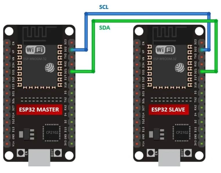
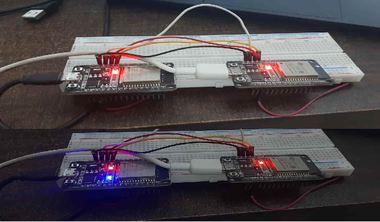
ESP32 I2C Master and Slave Connections Diagram
Make connections between both ESP32 boards with I2C communication pins given below in the table.
| ESP32 Master | ESP32 Slave | |
|---|---|---|
| SDA | GPIO21 | GPIO21 |
| SCL | GPIO22 | GPIO22 |
| GND | GND |
Install ESP32 I2C Slave Library
The wire. h library configures ESP32 in master mode only. To use ESP32 as a I2C slave device, we need to install ESP32I2CSlave library.
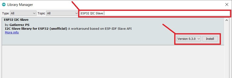
Open Arduino IDE and click on Sketch > Library > Manage Libraries.
When you click on the manage libraries option, you will get this window. In this window write ‘ESP32I2CSlave‘ in the search bar and press enter.
Select the highlighted library and click on install.
ESP32 I2C Master Code
// Wire Master Writer
// by Gutierrez PS <https://github.com/gutierrezps>
// ESP32 I2C slave library: <https://github.com/gutierrezps/ESP32_I2C_Slave>
// based on the example by Nicholas Zambetti <http://www.zambetti.com>

// Demonstrates use of the Wire and WirePacker libraries.
// Writes data to an ESP32 I2C/TWI slave device that
// uses ESP32 I2C Slave library.
// Refer to the "slave_receiver" example for use with this

#include <Arduino.h>
#include <Wire.h>
#include <WirePacker.h>

#define SDA_PIN 21
#define SCL_PIN 22
#define I2C_SLAVE_ADDR 0x04

void setup()
{
    Serial.begin(115200);           // start serial for output
    Wire.begin(SDA_PIN, SCL_PIN);   // join i2c bus
}

void loop()
{
    static unsigned long lastWireTransmit = 0;
    static byte x = 0;

    // send data to WireSlave device every 1000 ms
    if (millis() - lastWireTransmit > 1000) {
        // first create a WirePacker that will assemble a packet
        WirePacker packer;

        // then add data the same way as you would with Wire
        packer.write("x is ");
        packer.write(x);

        // after adding all data you want to send, close the packet
        packer.end();

        // now transmit the packed data
        Wire.beginTransmission(I2C_SLAVE_ADDR);
        while (packer.available()) {    // write every packet byte
            Wire.write(packer.read());
        }
        Wire.endTransmission();         // stop transmitting
        lastWireTransmit = millis();
        if(x==0)
          x = 1;
        else
        x = 0;
    }
}
ESP32 I2C Slave Code
// WireSlave Receiver
// by Gutierrez PS <https://github.com/gutierrezps>
// ESP32 I2C slave library: <https://github.com/gutierrezps/ESP32_I2C_Slave>
// based on the example by Nicholas Zambetti <http://www.zambetti.com>

// Demonstrates use of the WireSlave library for ESP32.
// Receives data as an I2C/TWI slave device; data must
// be packed using WirePacker.
// Refer to the "master_writer" example for use with this

#include <Arduino.h>
#include <Wire.h>
#include <WireSlave.h>

#define SDA_PIN 21
#define SCL_PIN 22
#define I2C_SLAVE_ADDR 0x04

#define LED 2

void receiveEvent(int howMany);

void setup()
{
    Serial.begin(115200);
    pinMode(LED, OUTPUT);
    bool success = WireSlave.begin(SDA_PIN, SCL_PIN, I2C_SLAVE_ADDR);
    if (!success) {
        Serial.println("I2C slave init failed");
        while(1) delay(100);
    }

    WireSlave.onReceive(receiveEvent);
}

void loop()
{
    // the slave response time is directly related to how often
    // this update() method is called, so avoid using long delays
    // inside loop(), and be careful with time-consuming tasks
    WireSlave.update();

    // let I2C and other ESP32 peripherals interrupts work
    delay(1);
}

// function that executes whenever a complete and valid packet
// is received from master
// this function is registered as an event, see setup()
void receiveEvent(int howMany)
{
    while (1 < WireSlave.available()) // loop through all but the last byte
    {
        char c = WireSlave.read();  // receive byte as a character
        Serial.print(c);            // print the character
    }

    int x = WireSlave.read();   // receive byte as an integer
    Serial.println(x);          // print the integer

    if(x == 1)
    {
        Serial.println("Setting LED active HIGH ");
        digitalWrite(LED, HIGH);
    }
    else if(x == 0)
    {
        Serial.println("Setting LED active LOW ");
        digitalWrite(LED, LOW);
    }
     Serial.println("");

}
Now upload the above sketches to master and slave ESP32 boards.
After uploading Arduino sketches to both ESP32 boards, open the serial monitor of a slave device, you will get these messages on the serial monitor:
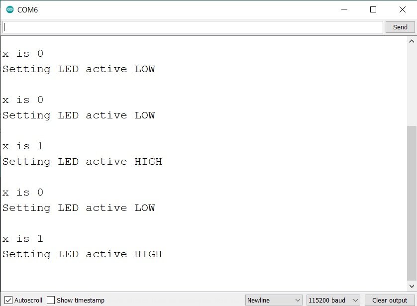
You will also see that the onboard LED of ESP32 slave will turn on and off with a delay of one second.
You may also like to read:
I’m building a nifty digital clock, using the TM1637 display, and am adding features to it. I successfully got connected to the ntp time pool that will adjust the RTC time if my RTC is off by more than 30 seconds. Then, I thought it’d be cool to add a 128×32 OLED to display the day of the week. This caused me headaches. I tried just declaring 18 and 19 as my OLED I2C pins. Surprising no one, this didn’t work and my project bricked. After monkeying around for a few weeks (and enlisting ChatGPT’s help) I was unable to get my RTC module and a small OLED module to work.
In an inspired moment, I thought I could “daisy-chain” the RTC and OLED to the same default I2C pins, 32 and 33 and voila it worked! And thanks to this article, I know how to establish correct pins to take advantage of ESP32’s two I2C busses correctly.
And if I want to add similar modules that have the same address, I can get a multiplexing module as you recommended!
Glad to hear your project is working! Using the same I2C pins was a great idea, and the multiplexer will definitely help with future modules. Keep up the good work!