In this tutorial, we will learn to use the I2C communication port of Arduino. Different Arduinos support at least one I2C port. Similarly, Arduino Uno also has one I2C port. We will learn to configure Arduino as an I2C master and an I2C slave device. In the end, for demonstration purposes, we will perform i2c communication between two Arduino boards.
Note: Although we will be using Arduino Uno in this tutorial. But concepts and coding examples will work on other Arduino boards such as Arduino Mega, nano, micro, etc.
Recommended Components
The following components are used in this project or are helpful for building it with the Arduino.
| Component | How it’s used in this project | Buy on Amazon |
|---|---|---|
| Arduino Uno R3 | The main controller board — this project uses two of them, one as I2C master and one as I2C slave. | Check Price |
| Breadboard | Solderless board to build and prototype the circuit without soldering. | Check Price |
| Jumper Wires | Used to connect the SDA, SCL, and ground lines between the two Arduino boards. | Check Price |
As an Amazon Associate we earn from qualifying purchases. Prices and availability are accurate as of the date/time indicated and are subject to change.
I2C Introduction
I2C means Inter-integrated circuit communication protocol. It is a 2-wire serial communication protocol for short range data transfer applications. It is a very popular communication protocol used in embedded projects to interface I2C based sensors, digit displays, and communication modules.
Devices that want to communicate with each connects through an I2C bus. I2C bus supports multiple slave devices and multiple master devices.
Many Sensors use this serial communication protocol to transfer their data to microcontrollers or through this protocol different slave circuits are able to communication with master circuits. It is only applicable for short distance data transmission.
I2C Pins
The distinguishing feature of I2C over SPI is that it uses only two wires to carry out communication. One wire is SCL (serial clock line) which synchronizes the transmission of data between devices and the other wire is SDA (serial data) which carries the actual data to be transmitted. These lines are open-drain lines which means these need to be connected to pull up resistors if devices are active low. Each slave device which is connected with the bus will have a unique 8-bit address.
The communication between specific devices using two wires is accomplished by the fact that each device has its own unique device ID or address and using this address; master can choose any specific device to communicate.
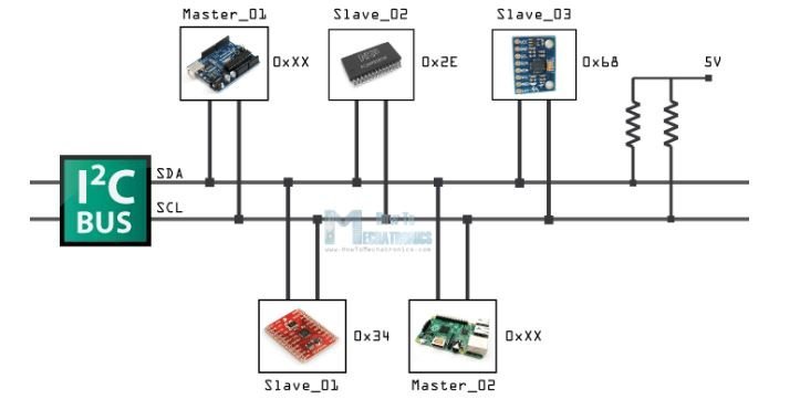
I2C Bus
This picture shows master and slave devices connected with the I2C bus. In this picture, Arduino and Raspberry Pi are acting as a master and MPU6050, sensor devices as a slave.
I2C bus consists of multiple devices such as slave and master Slave devices.
Slave Devices
Each slave devices has unique address that is utilized to recognize the device on the bus. In other words, slave address helps the master device to send information to a
specific slave device on the bus.
Master devices
Master devices can send and get information. Slave react to whatever an master sends. When sending information on the bus, just a single device can send
information at a time.
In short, we only need two wires for transferring data or communicate with different numbers of devices. As we all know that Arduino has limited pins, I2C allows to connect with multiple devices at a same time. only shortcoming is that you cannot use this protocol for long distance data transferring.
Data transfer bit by bit serially along a wire (the SDA line). Like SPI, I2C is concurrent, the output of bits is synchronized to the testing of bits by a clock signal shared
between the master and the slave.
Arduino I2C communication Pins
For I2C communication, different boards of Arduino have different pins dedicated as SDA and SCL pins. Below list shows these pin numbers in different boards.
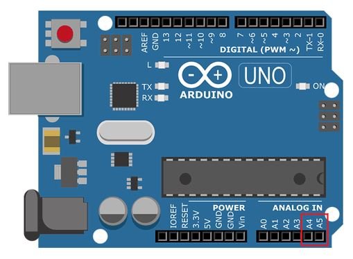
- In Arduino UNO, Pin A4 = SDA and Pin A5 = SCL
- For Arduino Mega2560, Pin 20 = SDA and Pin 21 = SCL
- In Arduino Leonardo, Pin 2 = SDA and Pin 3 = SCL
- For Arduino Due, Pin 20 = SDA and Pin 21 = SCL, SDA1, SCL1
Below figure shows SDA and SCL pins in Arduino UNO which will be used in this article.
Arduino I2C Communication Library
The “wire” library is used for I2C communication in Arduino. Following are important functions of this library.
Wire.begin(address)
The wire library is initiated using this command and join the I2C bus as master or slave. The address is optional. This address consists of seven bits for the slave devices. In case it is not specified; device joins the bus as Master.
Wire.requestFrom(address, quantity)
This command is used by the Master device for requesting the bytes from a slave device. “Available ()” and “read ()” functions can be used for collecting these bytes afterward. “Address” is the address of a specific slave device from which a request is to be made and “quantity” specify the number of bytes to be requested.
Wire.beginTransmission(address)
This command initiates the transmission of bytes with slave device of given address. Afterward, bytes to be transmitted are queued using write () function and these bytes are transmitted using endTransmission() function.
Wire.endTransmission()
The transmission of bytes initiated using wire.beginTransmission() function, is ended using this command.
This function accepts an argument. If argument is TRUE, stop command is sent after transmission of bytes and I2C bus is spared.
If argument is FALSE, it sends a restart command after transmitting bytes and bus is not spared and it prevent another master device from transmitting in between messages.
Wire.Write ()
This command performs one of 2 functions at a time.
- When a request is made by master, this function write data from slave device.
- In between calls of beginTransmission () function and endTransmission () function, this command is used to queue bytes for transmission.
Wire.read ()
After requestFrom () command, bytes which are transmitted from slave device to master device or master device to slave device; are read using this command.
Wire.available()
This function returns the number of bytes available for retrieval after calling read () function. In master device it is called after requestFrom() function and in slave device it is called inside onReceive () function.
Wire.onReceive(handler)
This registers a function which is called when transmission from master device is received by slave device. The function which is called is represented by handler.
I2C Communication Between Two Arduino Boards
In this section, we will see an example code to transfer data between two Arduino boards using the I2C bus. We will configure one Arduino board as an I2C master device and another Arduino board as an I2C slave device. Master will transfer numbers between 0-6 in sequence to the slave device. If the number received by the slave device is less than 3, an LED connected with pin D13 of slave Arduino will remain on otherwise LED remains off.

To build this program we need followings components:
- Two Arduinos (Master and slave)
- LED-Master
- LED-slave
- Connecting Wires
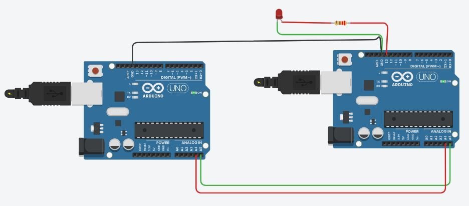
I2C connection between two Arduino Boards
The following figure shows the I2C connections between two Arduino boards. Also, it shows the connection of an LED with D13 of slave Arduino. Connect the LED’s anode pin with Arduino digital pin 13 through a 220 ohm current limiting resistor. The cathode pin will be grounded.
- Next to enable I2C communication, connect I2C pins A4 and A5 of master Arduino to the I2C pins of the slave Arduino.
- After that, by using jumper wires common the ground of both the Arduino boards.
- After making connections, upload the codes of both slave and master to Arduino boards.
Now first let’s discuss the Arduino master device code.
Arduino I2C Master Device Code
Here wire library has been included and variable x is initiated. The value of this variable will be transmitted to the slave device.
#include <Wire.h>
int x = 0;
Here wire.begin() function has been called. Detail can be found in above section. Also internal buffer has been initiated.
void setup()
{
  Wire.begin();
  Serial.begin(9600);
  pinMode(LED,OUTPUT);
}
Here transmission has been initiated with the slave address of 9. After this, the value of x has been queued for transmission over the I2C bus. The wire.write() function transmit current value of ‘x’ on I2C bus. Finally, the value of x has been transmitted and the bus has been spared using endTranmission () command.
Wire.beginTransmission(9);
Wire.write(x);
Wire.endTransmission();
Value of x is incremented by step of 1 in loop with a delay of 200milli seconds, if value of x is greater than 6, this value is reset to 0 and again incremented from 0.
x++;
if (x > 6)
  {
    x = 0;
  }
delay(200);
Complete Master Arduino Code
#include <Wire.h>
int LED=13;
int x = 0;

void setup()
{
  Wire.begin();
  Serial.begin(9600);
  pinMode(LED,OUTPUT);
}

void loop()
{
  Wire.beginTransmission(9);
  Wire.write(x);
  Wire.endTransmission();

  x++;
  if (x > 6)
  {
    x = 0;
  }
  delay(200);
}
Arduino I2C Slave Device Code
First, we define the symbolic name for pin D13 of Arduino. Pin D13 will turn on and off depending on received value from a master device. Also, we declare and initialize a variable x with zero. This variable x will be used to store the value received from a master Arduino.
#include <Wire.h> // add i2c library
int LED = 13;
int x = 0;
Inside the setup function, set LED pin as an ouput pin using pinMode() function. Also set the slave address of Arduino to 9.
 pinMode(LED, OUTPUT);
 Wire.begin(9);
 Wire.onReceive(receiveEvent);
 Serial.begin(9600);
Declarations and calling of function have been carried out as defined in the above section. Here receiveEvent () function has been registered by calling onReceive(handler) function.
void receiveEvent(int bytes)
{
  x = Wire.read();
}
This reciveEvent () function has been defined here. It reads the value from 1 to 6 which will be sent by the master device; and then stores this value in variable x which has been declared in the setup function of the program.
void loop()
{
  if (x <= 3)
  {
    digitalWrite(LED, HIGH);
  }
  else
  {
    digitalWrite(LED, LOW);
  }
}
If value of x received from master device is less than or equal to 3, LED at pin 13 is set to turn ON and if value of x is greater than 3, LED at pin 13 is set to turn OFF.
Complete Slave Device Code
#include <Wire.h>
int LED = 13;
int x = 0;

void setup()
{
  pinMode (LED, OUTPUT);
  Wire.begin(9);
  Wire.onReceive(receiveEvent);
  Serial.begin(9600);
}

void receiveEvent(int bytes)
{
  x = Wire.read();
}

void loop()
{
  if (x <= 3)
  {
    digitalWrite(LED, HIGH);
  }
  else
  {
    digitalWrite(LED, LOW);
  }
}
Hardware Demonstration
To see the demonstration, upload the master and slave codes to the Arduino boards. But, before uploading code, make sure to select the Arduino board from Tools > Board and also select the correct COM port to which the Arduino board is connected from Tools > Port.

Master Arduino will continuously transmit data over I2C bus and data will be between 0-6. Depending on data received by the slave device and conditions mentioned above Led at pin 13 is turned on and off.

Watch the video below:
Applications of I2C Communication
- This communication is used for color balance, changing contrast, and hue in monitors.
- In intelligent speaker, volume is changed using this communication method.
- It is used in reading diagnostic sensors like fan speed in computers.
- Turning power supply On and OFF in system components.
- Accessing real time clocks and NVRAM chips which keeps the user settings.
Advantages and Disadvantages of I2C communication
Advantages
It is adaptable because it upholds multiple master and multiple slave
communication.Only use two wires It is versatile can easily adapt to the requirements of different slave devices
ACK/NACK affirms that each edge has been effectively sent. Devices can be
introduced or eliminated on the bus.
Disadvantages
It is not applicable for long distance communication Only use two wires
It has Slow speed Requires more space because of the utilization of resistors
Complex as the quantity of devices increases.
Other I2C communication tutorials:
If you wish to add further data, say x & y how would you achieve ?