Recommended Components
The following components are used in this project or are helpful for building it with a PIC microcontroller.
| Component | How it’s used in this project | Buy on Amazon |
|---|---|---|
| PIC16F877A microcontroller | The 40-pin PIC MCU that runs this tutorial’s code. | Check Price |
| PICkit 5 programmer/debugger | Programs and debugs the PIC over the ICSP header. | Check Price |
| Breadboard | Solderless base for wiring the PIC and the project’s components. | Check Price |
| Jumper Wires | Make the connections between the MCU, components and power rails. | Check Price |
As an Amazon Associate we earn from qualifying purchases. Prices and availability are accurate as of the date/time indicated and are subject to change.
I2C Introduction
I²C protocol was invented by Philips semiconductors in the 1980s, to provide easy on-board communications between a CPU and various peripheral chips. I²C stands for Inter-Integrated Circuit. It is a short distance serial interface that requires only two bus lines for bi-directional data transfer. It is used for attaching lower-speed peripheral ICs to microcontrollers in short distance communication. Low-speed peripherals include external EEPROMs, digital sensors, I2C LCD, temperature sensors.Communication Lines
I²C protocol uses 2 signal lines, a serial data line (SDA) and a serial clock line (SCL). Any number of slaves and any number of masters can be connected to these 2 signals. Unlike UART Communication, this protocol requires a clock signal. Because this is synchronous communication. By using a clock signal, it achieves high-speed data transfer rate.- SDA line: This wire sends data to a slave device. Any data sent from one device to another goes through the SDA wire.
- SCL line: It provides the necessary synchronization clock for the data transfer.
HOW I2C Works?
Data is sent either direction on the serial data line (SDA) by the master or slave. Only a Master can start a data transfer and Slaves respond to the Master. It is possible to have multiple Masters on a common bus, but only one could be active at a time. The SCL clock line is always driven by the master.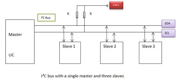 Both SCL and SDA lines are open-drain drivers and are connected to a positive supply voltage through pull-up resistors. I²C devices can only pull the line low, they cannot drive it high. When no device is pulling on the line, it will float high through the pull-up resistor. This is the reason why pull-up resistors are important in I²C.
I2C communication START AND STOP CONDITIONS BY MASTER
Each I²C command initiated by a master device starts with a START condition and ends with a STOP condition. For both conditions, SCL has to be high. After the Start condition, the bus is considered busy and can be used by another master only after a Stop condition is detected.- Start condition: A high to low transition of SDA.
- Stop condition: A low to high transition of SDA.

Slave Devices address
After the start condition, we need to specify the slave address. Because a single master device can send data to multiple slaves. Each salve will have a unique address. Each slave connected to the bus is software addressable by a unique 7-bit or 10-bit.7-bit Device Addressing
After the Start condition,the first byte sent is known as Control byte. The first seven bits of the control byte make up the slave address.
- The first four bits are fixed.
- The next three bits are set by hardware address pins (A0, A1, and A2) which allow the user to modify the I²C address. It allows up to eight devices to operate on the I²C bus.
- The eighth bit (LSB) is a data direction bit (R/W)
- ‘0’ in LSB indicates that the Master will write information to a selected slave
- ‘1’ in LSB indicates that the Master will read data from the slave
- When the receiver gets its address, it has to generate the Acknowledge signal. During this state the transmitter should release the SDA bus to allow the receiver to derive it. When receiver drives the SDA signal low it acknowledges that the address byte has been received.If the receiver does not drive SDA low, the condition is a no-acknowledge (NACK) and the operation is aborted
Acknowledge     =        0 volts
No Acknowledge   =     High volts.
When a control byte is sent, each device/slave in the system compares the first seven receiving bits with its address. If the address gets matched, the device considers itself addressed by the master. Now, it will behave as slave-receiver or slave-transmitter depending upon the value of the R/W bit.
10-bit Device Addressing
Every I²C device must have a built-in 7 bits address. So according to this, there would be only 128 different I²C device types in the world. But there are many more different I²C devices and there is a high probability that 2 devices have the same address on the I²C bus. To overcome this problem, devices often have multiple built-in addresses that we can select through external configuration pins on the device. To extend the range of available devices address, the I²C specification deduces a 10-bits addressing scheme.
- Instead of one, the two address words are used for device addressing.
- The first address word contains conventional code as “11110” on MSBsto aware the slaves on the bus of 10-bits device address. After that, it contains two MSBs of 10-bit address and Rd/Wr bit.
- The second address word contains 8 least significant bits (LSBs) of the 10-bit address. So this addition of bits ensures the backward compatibility with a 7-bit addressing scheme.
How I2C Data Transfer Works?
The byte put on the SDA line must be 8-bits long. The data is sent on the SDA line. The most significant bit (MSB) is sent first and the SCL line produces a synchronization clock. The data on the SDA line is considered valid when SCL is high. The high or low state of the data line can only be changed when the clock signal on the SCL line is LOW.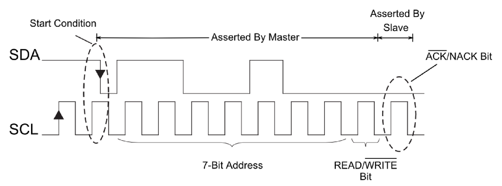 If the slave is not in a position to receive or transmit another complete byte of data it can hold the SCL line low to force the master into a wait state. Data transfer continues when the slave is ready for another byte of data and releases the clock line. To terminate the data transfer, a stop condition is generated by the master. And if the master still wishes to communicate on the bus it can generate another slave address along with repeated start condition without generating first stop condition.
Data Transfer Speed
For I2C bus, the clock speed can be chosen between- 100 Kbps in standard mode
- 400 Kbps in fast mode
- Up to 3.4 Mbps in high-speed mode
I2C Communication Module Pic Microcontroller
Till now, we have learned an introduction to I2C communication and how it works. In this section, we will learn about the I2C Communication module of Pic microcontroller and how to use it to transfer data through this two-wire communication protocol. There are popular compilers used for pic microcontrollers programming such as MPLAB XC8 and MikroC Pro for PIC. Firstly, we will see examples with MikroC pro and after that, we look at some examples with MPLAB XC8 Compiler.PIC I2C Communication with MikroC Pro
MikroC Pro for PIC provides a built-in library that we can easily use to transfer data to I2C-Slave devices. Unlike the Mplab XC8 compiler which does not provide built-in routines. Therefore, if we use MikroC Pro, we do not need to care much about the I2C module internal configuration register of Pic microcontrollers.MikroC Pro I2C communication Library
To use MikroC Pro for I2C communication, we just need to understand the working of each function associated with this library. These are seven functions used for various purposes such as module, initialization, transmit data, receive data, start and stop data transmission. Some microchip MCUs also have more than one I2C module in a single chip. But we can use same library for each I2C module. We just need to change the number shown at the end of each function prototype like this I2C2_Init().
I2C_Init Function
- It is used for the initialization with the required clock frequency. We should call this function inside the main function before using other routines.
- I²C module is initialized on the RC3 (SCL) and RC4 (SDA) pins of PIC16F877A microcontroller by I2C1_Init(100000).
- Some MCUs have multiple I²C modules. In order to use the desired I²C library routine, we simply change the number 1 in the prototype with the appropriate module number, i.e. I2C1_Init(100000);
I2C1_Start()
It checks either I2C_Bus is free or busy. This is a prototype that returns a short type variable. It return zero, if there is no error and line is free. For example, we can use if condition to evaluate output like this:if (I2C1_Start()==0) // checks if BUS is free
- I2C1_Repeated_Start (): It issues start signal continuously.
- I2C1_Is_Idle(): It returns one if bus is free. Otherwise, it returns zer0. Tests if the I²C bus is free.
- I2C1_Rd(): It is used to read acknowledged or not acknowledged signal from a slave device connected with the bus and reads one-byte data from the slave.
- I2C1_Wr(): This function writes data on the I2C bus and the only slave will be read that data which acknowledged the address.
- I2C1_Stop(): After the master device completes its data transmission, this function informs to the receiver that data transmission has completed.
IC2 Communication with PIC18f877a and EEPROM Circuit diagram
Microcontrollers are known as standalone chips as they have internal memory and processor embedded. The memory stores the code and other temporary variables for the execution of the program. Despite that memory, we can use non-volatile memory (permanent data storing) EEPROM. Sometimes we need more external EEPROM to store data permanently that we can use even after microcontroller turn off or resets.Now we will interface that I2C device with Pic microcontroller PIC16F877A. We will use the I2C library in MikroC for Pic MCU- In this example, PIC16F877A acts as a Master device and 24C64 EEPROM as a slave device.
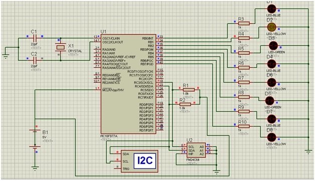
- Here we are using 24C64 EEPROM (an I2C device) as a slave.
- In this example code, we will examine how to write and read data from the I2C device and show the output on some LCD or LEDs.
- In Proteus, we need to connect I2C Debugger. SCL and SDA of I2C Debugger should be connected in parallel to SCL and SDA of 24C64. I2C Debugger can be found where CRO can be found in Proteus.
SDA: RC4 (Master) to 5 (Slave)
SCL: RC3 (Master) to 6 (Slave)
- To display the output: LEDs are connected to PORT B.
I2C Code Example MikroC Pro
This example code writes 00000001 to the first memory location, 00000010 to second and 000000100 to third and then so on sequentially up to 10000000. Then it is read sequentially and output (write) through PORTB.voidwrite_EEPROM(unsigned int address, unsigned intdat)
{
unsignedint temp;
I2C1_Start(); // issue I2C start signal
I2C1_Wr(0xA0); // send byte via I2C (device address + W)
temp = address >> 8; //saving higher order address to temp
I2C1_Wr(temp); //sending higher order address
I2C1_Wr(address); //sending lower order address
I2C1_Wr(dat); // send data (data to be written)
I2C1_Stop(); // issue I2C stop signal
Delay_ms(20);
}
unsignedintread_EEPROM(unsigned int address)
{
unsignedint temp;
I2C1_Start(); // issue I2C start signal
I2C1_Wr(0xA0); // send byte via I2C (device address + W)
temp = address >> 8; //saving higher order address to temp
I2C1_Wr(temp); //sending higher order address
I2C1_Wr(address); //sending lower order address
I2C1_Repeated_Start(); // issue I2C signal repeated start
I2C1_Wr(0xA1); // send byte (device address + R)
temp = I2C1_Rd(0u); // Read the data (NO acknowledge)
I2C1_Stop();
return temp;
}
void main()
{
unsignedint a, i;
TRISB = 0; // To make it output port
PORTB = 0; // To make it output port
CMCON = 0x07; // To turn off comparators
ADCON1 = 0x06; // To turn off analog to digital converters
I2C1_Init(100000);
do
{
for(i=0,a=1;i<8;i++)
{
write_EEPROM(i, a);
Delay_ms(30);
a = a<<1;
}
for(i=0;i<8;i++)
{
PORTB = read_EEPROM(i);
Delay_ms(100);
}
} while(1);
}Check simulation:PIC18F4550 I2C Programming MPLAB XC8
In this section, we will see how to program I2C module of PIC184550 microcontroller using MPLAB XC8 compiler. To use MPLAB XC8 compiler, we must understand control and status registers of I2C communication module. Now let’s get into the details of control and data registers.PIC184550 Microcontroller has Master Synchronous Serial Port (MSSP) module. MSSP supports SPI and I2C communication. MAAP module can be used either in SPI or I2C modes or both also.PIC18F4550 two pins are to transfer data using this two-wire communication and associated pins are:- Serial clock (SCL) – RB1/AN10/INT1/SCK/SCL
- Serial data (SDA) – RB0/AN12/INT0/FLT0/SDI/SDA
PIC18F4550 I2C Module Registers
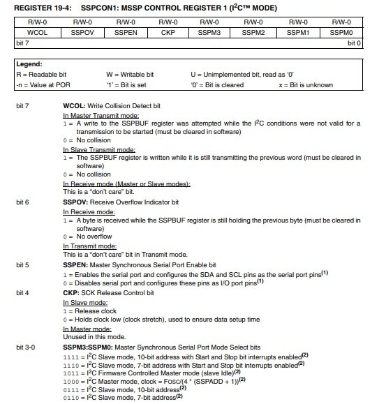
These are the six registers used for two-wire communications. We must configure these registers.MSSP Control Register 1 (SSPCON1)
SSCCON1 configuration register performs various control functions such as:- Write collision detection
- Receive buffer overflow indicator
- I2C Communication port enable/disable
- Model section such as a 7-bit address, 10-bit address, master mode clock frequency
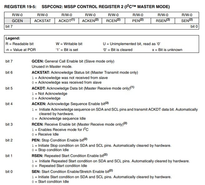
MSSP Control Register 2 (SSPCON2)
SSPCON2 register has different settings for slave and master mode. This picture shows the configuration of the SSPCON2 register in the master mode. In master mode, SSPCON2 offers these features:- Acknowledge status bit flag and data bit flag from slave devices connected with I2C bus
- Settings for stop, start and repeated start bits.
- Enables Receive mode
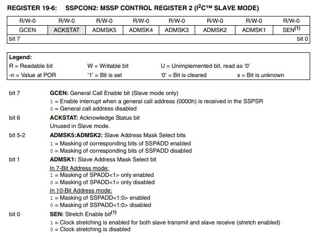
 Similarly, this picture shows settings for slave mode configuration. In slave mode, it offers these settings:
- Provide interrupt after receiving general address call from SSPSR.
- Slave address masking
MSSP Status Register (SSPSTAT)
Firstly, SSPSTAT (SMP_bit) register control Slew Rate (High-speed mode or standard speed mode).SSPSTATbits.SMP = 1; // selects Standard Speed mode (100 kHz and 1 MHz) SSPSTATbits.SMP = 1; // slew rate control enabled for High-Speed mode (400 kHz)
CKE Bit
It selects SMBus S. We can configure it in Master or Slave mode like this:SSPSTATbits.CKE = 1 ; // Enable SMBus specific inputs SSPSTATbits.CKE = 0 ; // Disable SMBus specific inputsD/A: Data/Address bitIn Master mode, this bit is reserved. We can only use it to configure in slave mode. It indicates either received or transmitted byte was data or address.
SSPSTATbits.D/A = 1;   //Indicates that the last byte received or transmitted was data
SSPSTATbits.D/A = 0;  // Indicates that the last byte received or transmitted was address
P: Stop bit
It shows the status of a stop bitSSPSTATbits.P = 1 // Indicates that a Stop bit has been detected last SSPSTATbits.P = 0 //Stop bit was not detected last
S: Start
It shows a start bit is detected.SSPSTATbits.S = 1 // Indicates that a Start bit has been detected last SSPSTATbits.S = 0 // Start bit was not detected lastR/W: Read/Write Information bitIt shows different information for master and slave mode.In Slave mode:
SSPSTATbits.R = 1  // Read
SSPSTATbits.R = 0  //Write
In Master mode
SSPSTATbits.R = 1  // Transmit is in progress
SSPSTATbits.R = 0  //Transmit is not in progress
UA: Update Address bit (10-Bit Slave mode only)
This flag bit shows address update status.SSPSTATbits.UA = 1 // Indicates that the user needs to update the address in the SSPADD register SSPSTATbits.UA = 0 // Address does not need to be updated
BF: Buffer Full Status bit
BF bits shows the status of SSPBUF register either it is empty or FullIn Transmit mode:SSPSTATbits.BF = 1 //SSPBUF is full SSPSTATbits.BF = 0 // SSPBUF is emptyIn Receive mode:
SSPSTATbits.BF = 1 //SSPBUF is full (does not include the ACK and Stop bits)
SSPSTATbits.UA = 0 //SSPBUF is empty (does not include the ACK and Stop bits)
Serial Receive/Transmit Buffer Register (SSPBUF)
This register used to hold that we transmit or receive with I2C protocol. This is basically a buffer register to which we write and read data bytes.MSSP Shift Register (SSPSR) – Not directly accessible
This is a shift register used in PIC microcontroller I2C protocol. We used it to send or receive data in/out from SDA wire.MSSP Address Register (SSPADD)
This register has two different functions in slave or master mode. In slave mode, it holds the address of a slave device. When this module is configured as a master, it is used to define a data transfer rate or generate a baud rate. In master mode, only lower seven bits are used. We can use this formula to calculate SSPADD value for the desired baud rate :Output = fOSC / 4 SSPADD = ( Output/ Baud rate ) -1Load this calculated value in the SSPADD register. It defines the clock frequency.
How to Configure I2C Master Mode
In this section, we will see how to write a driver for the I2C master mode for PIC Microcontroller using MPLAB XC8 compiler.In master transmitter mode, PIC microcontroller sends serial data through the SDA line and outputs clock through the SCL line. At the start, PIC18F4550 sends the slave address on the SDA line (address of receiving device ) and the Read/Write (R/~W) bit. Initially, the Read/~Write bit will be zero. After that acknowledge bit will be received from a slave device, based on the status of acknowledge. Start and stop bits show the start and end of the serial data transfer.To select master mode, we need to set/clear some bots of SSPCON1 such as SSPM and SSPEN. We need to follow these steps by configuring corresponding registers.- First, enable master mode by setting/clearing appropriate bits SSPCON1 register of PIC18F4550
- After that, we need to set start-enable bit SEN (SSPCON2<0>)
- Load value of salve address to SSPBUF register
- Sends one byte which contains address and R/~W bit value to the SDA line
- After that receive ACK bit from the slave device and store its value in SSPCON2 register (ACKSTAT bit)
- Based on the ACKSTAT bit, I2C Module generates interrupt on the 9th clock cycle. It will set the SSPIF interrupt bit.
- After that Programer can load the 8-bit data to the SSPBUF register that user wants to transmit to the slave device ( through SDA line)
- After that receive ACK bit from the slave device and store its value in SSPCON2 register (ACKSTAT bit)
- I2C Module generates interrupt on the 9th clock cycle. It will set the SSPIF interrupt bit.
- The user generates a Stop condition by setting the Stop Enable bit, PEN (SSPCON2<2>).
- Interrupt is generated once the Stop condition is complete.
PIC Microcontroller I2C Master Mode Driver
Now we will see I2C master driver.I2C_IDLE() function checks the status of the bus. It checks either I2C bus is busy or free. is It completed the last operation successfully?void I2C_IDLE() { while ((SSPSTAT & 0x04) || (SSPCON2 & 0x1F)); }
I2C_Initialize_Master() function enables master mode and generates clock frequency by uploading a value to the SSPADD register.
void I2C_Master_Init()
{
SSPCON = 0x28;  // enable I2C pins SCL and SDA for serial communication
SSPCON2 = 0x00;
SSPSTAT = 0x00;  //slew rate enables for high speed control
SSPADD = ((_XTAL_FREQ/4)/I2C_BaudRate) - 1;
TRISC3 = 1;  //Set as a digital input
TRISC4 = 1;  //Set as a digital input
}
This function should be called before using other functions.
void I2C_Start()
{
I2C_IDLE();
SSPCON2bits.SEN = 1;  // initial start condition on SDA line
}
This function sends stops condition to end data transfer.
void I2C_Stop()
{
I2C_IDLE();
SSPCON2bits.PEN = 1; // Initiate Stop condition on SDA and SCL pins
}
This function sends a signal to a slave that the master wants to send more data. It will restart the data transfer.
void I2C_Restart()
{
I2C_IDLE();
SSPCON2bits.RSEN = 1; // Initiate Repeated Start condition on SDA and SCL pins.
}
These two functions provide an ACK signal after sending a 7bit/10bit address or 8bit data.
void I2C_ACK(void)
{
  I2C_IDLE();
  SSPCON2bits.ACKDT = 0; //Acknowledge Data bit
  SSPCON2bits.ACKEN = 1;  // Acknowledge Sequence Enable bit(
}
void I2C_NACK(void)
{
I2C_IDLE();
SSPCON2bits.ACKDT = 1;
SSPCON2bits.ACKEN = 1;
}
I2C_Write() used to transmit address and data through the SDA wire.
// input parameter to this function can be a byte ( either address or data)
unsigned char I2C_Write(unsigned char Data)
{
I2C_IDLE();   // wait untill I2C_Bus of PIC18F4550 microcontroller becomes free
SSPBUF = Data; // store data inside SSPBUF register of PIC18F4550 microcontroller
I2C_Wait();
return ACKSTAT; //return status of data or address transmission
}
This I2C_Read_Byte() routine reads a byte from the I2C_Bus and returns its value.
unsigned char I2C_Read_Byte(void)
{
SSPCON2bits.RCEN = 1; // Enable & Start Reception
while(!SSPIF); // Wait Until Completion
SSPIF = 0; // Clear The Interrupt Flag Bit
return SSPBUF; // Return The Received Byte
}
PIC Microcontroller I2C Slave Drive
In this section, we will see how PIC18F4550 microcontroller I2C module works in slave mode. After that, we will see its driver in MPLAB XC8 Compiler.Slave Mode Operation
In order to use PIC18F4550 I2C in slave mode, we must configure SDA and SCL pins as inputs ( RC3 and RC4). As you know that in I2C communication, every slave device has a unique address. Therefore, firstly we should assign an address to the slave module of Pic microcontroller. Because whenever a master device wants to send data to pic microcontroller slave, first it will send an address. If this address matches with the address of your device, a microcontroller (acting as a slave ) will generate an interrupt. Because data transfer occurs from master to the slave upon address match. Follow these steps:- Load the slave address into SSPADD register
- Set slew rate as default rate (low-speed operation ) using SSPSTAT register SMP bit
- Enable I2C slave mode option with SSPCON1 register SSPM3: SSPM0 bits ( four options possible for slave mode)
- Enable global, peripherals and I2C module interrupts
Slave Initialization Code
I2C_Slave_Initialization function configures SSPSTAT, SSPCON1, SSPCON2 and INTCON registers used for pic microcontroller slave mode configuration.- SSPCON1 configures I2C Slave mode with a 7-bit address by setting SSPM3: SSPM0 = 0110.
- SSPCON enables clock stretching
void I2C_Slave_Initialization(char address)
{

  TRISC3 = 1;     // Set RC3/SDA pins as a input pin
  TRISC4 = 1;     // Set RC4/SCL pins as a input pin
  SSPADD = Address;  // store the address of slave in SSPADD register
  SSPSTAT = 0x80; //  set standard slew rate
  SSPCON1 = 0x36; // Select & Enable I2C (Slave Mode)
  SSPCON2 = 0x01; // Enable Clock Stretching
  PIR1bits.SSPIF = 0;      // Enbable Interrupts
  PIE1bits.SSPIE = 1;     // Enable  PICI2C module interrrupt
  INTCONbits.PEIE = 1;    // Enable peripheral interrupt
 INTCONbits.GIE = 1;    // Enable global interrupt

}
PIC I2C Slave Data Receiving Code on Interrupt
This is an interrupt service routine used to read data/address from I2C bus on interrupt.void __interrupt() ISR(void)
{
if(PIR1bits.SSPIF)
{
CKP = 0; // strecth the clock signal to low
if (SSPCON1bits.SSPOV || SSPCON1bits.WCOL) // check errors such as collision and buffer overrflow
{
char receiver = SSPBUF; // read the value from SSPBUF to clear it
SSPCON1bits.SSPOV = 0; // reset overflow detection flag bit
SSPCON1bits.WCOL = 0; // eset collision detection flag bit
SSPCON1bits.CKP = 1; // Release Clock from low
}
if(!(SSPSTATbits.R_nW)) // Read
{
char receiver = SSPBUF; // read the value from SSPBUF to clear it
while(!BF);
RX_Data = SSPBUF; // Read The Received Data Byte
CKP = 1; // Release Clock Line SCL
}
SSPIF = 0; // clear I2C interrupt flag
}
}
Hi Bilal i am new to pic and i am using pic16f877a uc. I have a doubt is the I2C library in Built in Mickro ide or we should install it separately. If it should be installed separately can you please assist
But SPI is faster, easy to configure, easy to convert, allow frame sync etc. are it’s advantages.
yes but required more lines and only few devices can be connected “slave” + only one master
hey can you send me a file of this micro c. its giving errors
I am trying to interface LCD 16×2 with pic 18f25k22 using i2c mcp23008 and i am get an error of i2c.h not found
Sir what are the headers files for the above code programmed in microC??
The sample code calls I2C_Wait() but does not define it!
Hello teelay,
I noticed this too, did you ever find why? Or did you find a solution to replace it? i thought of a for loop to hold the proccess but it’ll block it complitely, you think it would work?