This guide will assist you in interfacing the external ADC module AD1115 with ESP32. This is done to measure analog voltages with high accuracy. The ADS1115 external ADC module can send data over the I2C protocol. For learning more about I2C communication, you can check out our in-depth tutorial I2C Communication Protocol Basics. Now moving on to the module, it consists of four analog channels named as A0, A1, A2, and A3 respectively.
At the end of this guide, we will provide an example of analog voltage measurement with ADS1115 and ESP32. This will include explanation and a complete code schematic to help you understand this tutorial.
Recommended Components
The following components are used in this project or are helpful for building it with the ESP32.
| Component | How it’s used in this project | Buy on Amazon |
|---|---|---|
| ESP32 Development Board (DevKit V1) | The main microcontroller board that runs the project code and controls all connected parts. | Check Price |
| Micro USB Cable | Connects the ESP32 to your computer to upload code and provide power. | Check Price |
| Breadboard | Lets you build the circuit and connect components without soldering. | Check Price |
| Jumper Wires | Used to wire the ESP32 to the other components on the breadboard. | Check Price |
As an Amazon Associate we earn from qualifying purchases. Prices and availability are accurate as of the date/time indicated and are subject to change.
Why do we need to use an external ADC with ESP32?
Although, ESP32 has two built-in ADC modules namely; ADC1 and ADC2. These two modules are of 12-bits each and further divided into 8 and 10 channels respectively.
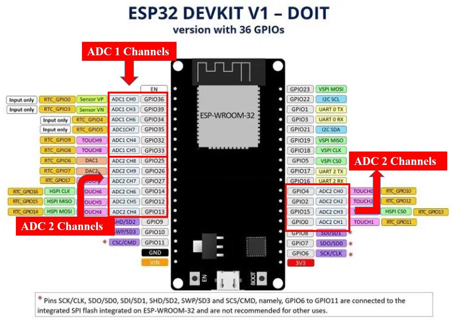
To learn in-depth about ESP32 ADC channels and their working you can refer to our article ESP32 ADC tutorial. But, we will discuss some of the issues here.
- Channel limitation due to overlapping functionality of touch pins (in ADC2) and internal reference voltage measurements (in ADC1).
- Non-linear characteristics and behavior during voltage measurement via ADC channels.
- Very low resolution of ESP32 ADC, it is unable to differentiate between 1mV and 2mV signals. Which can be very challenging for people requiring accurate results.
In order to resolve these issues, we can use an external high resolution programmable ADC IC, such as ADC1115 external ADC module.
Reasons to use External ADC Converter
Their are two main reasons to use External ADC converter with ESP32
Low resolution and non linear behavior: ESP32 has low resolution and non-linear behavior in its ADC channels, this issue can be resolved easily by connecting an external ADC module with ESP32. This will enable ESP32 to measure analog signal with higher accuracy. Other than this ESP32 has all the excellent features expected from a development board for IOT projects.
Interfacing issues : For example, you want to interface LM35 temperature sensor with ESP32, you can not connect it directly due to low resolution and inaccurate behavior of built-in analog to digital converter of ESP32. LM35 temperature sensor gives the output of 1mV per one degree centigrade of temperature. Built-in ADC can not measure 1mV accurately and so ESP32 fails to provide accurate data. This issue can also be resolved by connecting External ADC converter.
Introduction to ADS1115 External ADC
ADS1115 is a 16-bit analog to digital converter that consists of four analog channels. It can be used to measure both positive and negative voltages. ADS1115 works in Single Ended Differential mode or comparator mode.
| Operating Mode | Output |
| Single Ended Differential | This mode can measure positive voltages only. So no negative output can be processed in this mode. |
| Comparator | The Comparator mode is capable of processing both the positive as well as the negative voltages. It becomes very useful when battery voltages are measured. |
We can interface it with any microcontroller having I2C communication support. It has four modes and It also has a programmable comparator which can make it more effective for projects.
Features of ADS1115
ADS1115 is a 16-bit I2C protocol based ADC having four analog channels. It provides output in signed integer format. From total 16-bits, one bit is assigned for positive and negative number. Therefore, only 15 bits are used to measure the voltage and ADC resolution is calculated according to these 15 bits.
- We get 2^15 = 32,768 possible output values for every analog input.
- The range of possible digital output is between 0 – 32767.
- These 15 bits are used to get the magnitude of voltage through I2C communication.
- The weight of every bit can be defined with the Programmable Gain Amplifier (PGA) by setting a reference voltage value.
- In the default mode, the reference voltage value is +/-6.144 volts.
- The digital output is represented as 0 for 0V and 32767 for 6.144V.
- But we can not measure 6.144 volts directly with this chip (ESP32). The maximum voltage which we can measure depends on the supply voltage to the chip, which is 5.5 volts in case of ADS1115.
Resolution of ADS1115
- We can calculate the resolution of ADS1115 External ADC by dividing maximum voltage (6.144V) with maximum digital output (32767), which becomes equal to 0.1875mV.
- So the minimum analog voltage we can measure with ADS1115 external I2C ADC is 0.1875mV which is almost 50% greater in accuracy than the built-in analog to digital converter module of ESP32.
Pinout of ADS1115

It consists of four pins and the table below shows functionality of each pin.
| Pin name | Functionality |
|---|---|
| Vdd ( Power supply pin) | Connect power supply between 2.2 – 5.5 volts |
| GND ( Common reference pin ) | Connect with ground pin of power supply |
| SCL | I2C SCL ( serial clock pin) |
| SDA | I2C SDA ( Serial data pin) |
| ADDR | I2C slave select pin or address |
| ALRT | Alert/Ready |
| A0 | Analog channel 0 |
| A1 | Analog channel 1 |
| A2 | Analog channel 2 |
| A3 | Analog channel 3 |
We can set 4 different addressing modes by connecting the address pin with SCL, SDA, GND or VDD. Table below provides description on connection of address pin with SCL, SDA, GND or VDD pin according to the address value.
| ADDR pin value | Connection with Pin |
|---|---|
| 0x48 | Connect address pin to GND |
| 0x49 | Connect address pin to VDD |
| 0x4A | Connect address pin to SDA |
| 0x4B | Connect address pin to SCL |
ADDR pin is used for the selection of four different devices with one pin. So, we can connect it with any of the four pins listed in the table. You can explore further about addressing modes by reading this datasheet.
ADS1115 Library in Arduino IDE
We will be using Arduino IDE to program ESP32. If you are using Arduino IDE for the first time with ESP32, you can refer to this tutorial:
As mentioned in the previous sections, ADS1115 communicates data to ESP32 over I2C protocol. We need to use I2C pins of ESP32 to read the data. To handle communication and receive measured voltage over I2C protocol, we can use the ADS1115 library of Adafruit. Follow these steps to install library.
- To install the library, open your Arduino IDE and follow this menu Sketch > Include Library > Manage Libraries and click on manage libraries.
- After that type “Adafruit” in search bar and select ADS1X15 to install it.
- After installing the library click on close button and restart Arduino IDE.


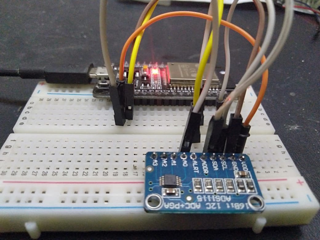
Interfacing ADS1115 External ADC with ESP32
Now we will make the connections according to the layout given below:

| ESP32 | ADS1115 external ADC |
|---|---|
| VDD | VDD |
| GND | GND |
| GPIO21 ( SDA Pin ) | SDA |
| GPIO22 ( SCL Pin ) | SCL |
| GND | ADDR |
| Analog voltage signal | A0 |
Here we use GPIO pin 21 and 22 for I2C communication. Connect the Analog signal to the voltage you want to measure with A0 pin of ADS1115.
Code to Measure Analog Voltage
Now open your Arduino IDE and paste the following code to your code editor window. After compiling the code, upload it to the ESP32 by clicking on the upload button.
#include <Wire.h>
#include <Adafruit_ADS1015.h>

Adafruit_ADS1115 ads(0x48);
float Voltage = 0.0;

void setup(void)
{
Serial.begin(9600);
ads.begin();
}

void loop(void)
{
int16_t adc0;

adc0 = ads.readADC_SingleEnded(0);
Voltage = (adc0 * 0.1875)/1000;

Serial.print("AIN0: ");
Serial.print(adc0);
Serial.print("\tVoltage: ");
Serial.println(Voltage, 7);
Serial.println();

delay(1000);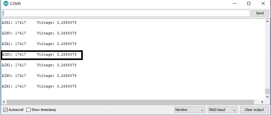
}- After uploading the code, open up Serial Monitor, you will see the output of voltage and adc0 on the serial monitor.
- For demonstration, I have connected VDD pin of ESP32 with analog channel zero.
- As you can see, we are getting close to 3.3 volts on Serial Monitor which is the operating voltage of ESP32 board, you can verify this output by measuring voltage on VDD pin of ESP32 with the help of voltmeter.

Code working
The first two lines add the library of ADS1115 and I2C communication protocol.
#include <Wire.h>
#include <Adafruit_ADS1015.h>
The next line defines the sensor type along with the address mode, we are using ADS1115. But you can also use this library with other versions of External ADC like ADS10115. The second line declares a variable of float type to store the voltage value.
Adafruit_ADS1115 ads(0x48);
float Voltage = 0.0;
Inside the setup() function, Serial.begin() function defines the baud rate of 9600 and ads.begin() function starts to read adc value.
Serial.begin(9600);
ads.begin();
Inside the loop() function , first we initialize the 16 bit long integer variable adc0 which is used to store the output of analog channel zero.
int16_t adc0;ads.readADC_SingleEnded(0) function reads the ADC channel 0 for digital value and store this value in adc0 integer variable. The next statement converts (adc0 * 0.1875)/1000 ADC’s value into the voltage stores it in the Voltage variable. One thing to note here is that 0.1875 is the resolution of ADS1115 ADC module.
adc0 = ads.readADC_SingleEnded(0);
Voltage = (adc0 * 0.1875)/1000;
Serial.print() functions prints the value of ADC and voltage on serial monitor. The delay() function adds a delay of one second after every reading.
Serial.print("AIN0: ");
Serial.print(adc0);
Serial.print("\tVoltage: ");
Serial.println(Voltage, 7);
Serial.println();
delay(1000);
In summary, in this tutorial, we have discussed the following concepts:
- Introduction to ADS1115 external I2C based ADC
- How to use it with ESP32
- How to measure voltage with ADS1115 and ESP32
You can check ESP32 projects also:
Hi, in Your connection picture You have wrongly specified VDD and GND connections on the ESP32 side.
Hi Pawel
Thanks for pointing out. We will update the picture after making corrections.
But you didn’t !!
The pin labels are correct, they are just wider than the pin pitch so the labels creep downward with respect to their pin
Is it possible to put 2 or more ADS1115 to the same I2C connection.
I found the way to connect up to four ADS1115 to the same I2C connection.
This TI pdf tells how to do it.
https://www.ti.com/lit/ds/symlink/ads1114.pdf
Here is a short form “how to”:
9.5.1.1
I2C Address Selection
The ADS111x have one address pin, ADDR, that configures the I2C address of the device.
This pin can be connected to GND, VDD, SDA, or SCL, allowing for four different addresses to be selected with one pin, as
shown in Table 4.
The state of address pin ADDR is sampled continuously. Use the GND, VDD and SCL addresses first.
If SDA is used as the device address, hold the SDA line low for at least 100 ns after the SCL line goes low to make sure the device decodes the address correctly during I2C communication.
Table 4.
ADDR Pin Connection and Corresponding Slave Address
ADDR PIN CONNECTION SLAVE ADDRESS
GND 1001000 (48)
VDD 1001001 (49)
SDA 1001010 (50)
SCL 1001011 (51)
Hi,
Thanks for this, very interesting, I have a comment:
You wrote:
The scaling factor is .01V/°C. It mean for every 1°C, LM35 temperature sensor provides 100mV at the output.
That should be 10mV for every 1C, not 100mV
Example:
250mV=25C
1000mV=100C
Cheers,
Andrew
Hi Thanks for pointing out, we will fix this.
This sketch seems to work happily on an ESP8266 as well, connecting SCL to GPIO5 and SDA to GPIO4, VDD to 3.3v and GND to GND.
Hi Tony,
This code works straightforward with ESP8266 and even Arduino also. You just need to change I2c pins according to the selected development board and this is the beauty with Arduino IDE based codes and maximum number of codes are easily portable to other boards also.
Any updates now that the Adafruit_ADS1X15 library had been updated? Old code is broken BTW.
You can still use the previous version by downloading it from their GitHub repository.
This code works for me with the up to date library:
#include
#include
//Adafruit_ADS1115 ads(0x48);
Adafruit_ADS1115 ads;
float Voltage = 0.0;
void setup(void)
{
Serial.begin(9600);
ads.setGain(GAIN_ONE);
//ads.begin();
if (!ads.begin()) {
Serial.println(“Failed to initialize ADS.”);
while (1);
}
}
void loop(void)
{
int16_t adc0;
adc0 = ads.readADC_SingleEnded(0);
Voltage = ads.computeVolts(adc0);
//Voltage = (adc0 * 0.1875)/1000;
Serial.print(“AIN0: “);
Serial.print(adc0);
Serial.print(“\tVoltage: “);
Serial.println(Voltage, 7);
Serial.println();
delay(1000);
}
Hello brother!
This code didn’t work for me. Maybe it will be for the version of the library.
hi i have a problem when binding the above code with sending data over wifi is that a common problem with a solution ?
#include
#include
#include
#include
#include
#define SENSOR_ID “2”
#define SERVER_IP “192.168.1.232”
#ifndef STASSID
#define STASSID “XXXXXX”
#define STAPSK “XXXXXX”
#endif
//display
#include // Only needed for Arduino 1.6.5 and earlier
#include “SH1106Wire.h” // legacy: #include “SH1106.h”
#include “SH1106.h”
SH1106 display(0x3c, SDA, SCL); // ADDRESS, SDA, SCL
#define DEMO_DURATION 3000
typedef void (*Demo)(void);
int demoMode = 0;
//
const int potPin = 34;
String apiPath=”http://” SERVER_IP “/api/StoreReading”;
String reading=”-9999″;
// GPIO where the DS18B20 is connected to
const int oneWireBus = 4;
#define USE_SERIAL Serial
WiFiMulti wifiMulti;
float SensorValue=0.000;
Adafruit_ADS1115 ads;
void setup(void)
{
USE_SERIAL.begin(115200);
USE_SERIAL.println();
USE_SERIAL.println();
USE_SERIAL.println();
for(uint8_t t = 4; t > 0; t–) {
USE_SERIAL.printf(“[SETUP] WAIT %d…\n”, t);
USE_SERIAL.flush();
delay(1000);
}
USE_SERIAL.println(“Integrate Data Logger Sensor.”);
USE_SERIAL.print(“Server IP: “);
USE_SERIAL.println(SERVER_IP);
USE_SERIAL.print(“Sensor ID: “);
USE_SERIAL.println(SENSOR_ID);
USE_SERIAL.println();
wifiMulti.addAP(STASSID, STAPSK);
//Display
display.init();
display.flipScreenVertically();
display.setFont(ArialMT_Plain_10);
//
// cpu frq. reduce
setCpuFrequencyMhz(80);
}
void drawFontFaceDemo() {
// Font Demo1
// create more fonts at http://oleddisplay.squix.ch/
display.setTextAlignment(TEXT_ALIGN_LEFT);
display.setFont(ArialMT_Plain_16);
display.drawString(0, 20, reading+” PSI”);
}
Demo demos[] = {drawFontFaceDemo};
int demoLength = (sizeof(demos) / sizeof(Demo));
long timeSinceLastModeSwitch = 0;
void loop(void)
{
ReadSensor();
// the display
display.clear();
// draw the current demo method
demos[demoMode]();
display.setTextAlignment(TEXT_ALIGN_RIGHT);
display.drawString(10, 128, String(millis()));
// write the buffer to the display
display.display();
if (millis() – timeSinceLastModeSwitch > DEMO_DURATION) {
demoMode = (demoMode + 1) % demoLength;
timeSinceLastModeSwitch = millis();
}
////
// wait for WiFi connection
if((wifiMulti.run() == WL_CONNECTED)) {
HTTPClient http;
USE_SERIAL.print(“[HTTP] begin…\n”);
// configure traged server and url
//http.begin(“https://www.howsmyssl.com/a/check”, ca); //HTTPS
http.begin(apiPath); //HTTP
http.addHeader(“Content-Type”, “application/x-www-form-urlencoded”);
String postData = “sensor_id=” SENSOR_ID “&reading=”+reading;
int httpCode = http.POST(postData);
USE_SERIAL.print(“[HTTP] POST…\n”);
// start connection and send HTTP header
// httpCode will be negative on error
if(httpCode > 0) {
// HTTP header has been send and Server response header has been handled
USE_SERIAL.printf(“[HTTP] GET… code: %d\n”, httpCode);
// file found at server
if(httpCode == HTTP_CODE_OK) {
String payload = http.getString();
USE_SERIAL.println(payload);
}
} else {
USE_SERIAL.printf(“[HTTP] GET… failed, error: %s\n”, http.errorToString(httpCode).c_str());
}
http.end();
}
esp_wifi_set_ps(WIFI_PS_MAX_MODEM);
delay(1000);
}
void ReadSensor(){
int16_t adc0;
//adc0 = ads.readADC_SingleEnded(0);
SensorValue=adc0;
reading=String(SensorValue);
}
I’m trying to use two ADS1115’s, one at 0x48, and one at 0x49…
But the code example fails Adafruit_ADS1115 ads(0x48);
Apparently that is no longer how you call out the address of the device.
I can only get Adafruit_ADS1115 ads; to work, and I can’t see how to set the address for the 0x49.
It looks to my newbie eye that the address is hard coded in the .h and the .cpp files.
I’m SURE I’m missing something simple, but am quite stumped. Thank you….
Please fix the ESP32 image in the interfacing diagram. The pin labels need to match the pins. This is still causing confusion after several years.
Hi, Whats the max voltage?
from ADS1115 datasheet :
Analog input voltage AIN0,1,2 & 3 : from GND-0.3v to VDD+0.5V, so if VDD=5V, the max input voltage on AINx = 5.3V
in the include section a had error massage:
#include
#include
Adafruit_ADS1115 ads;
error massage:(I tried different version of the library with similar result)
In file included from C:\Users\Administrator\Documents\Arduino\libraries\Adafruit_BusIO\Adafruit_SPIDevice.h:9:0,
from C:\Users\Administrator\Documents\Arduino\libraries\Adafruit_BusIO\Adafruit_SPIDevice.cpp:1:
C:\Users\Administrator\AppData\Local\Arduino15\packages\esp32\hardware\esp32\1.0.1\libraries\SPI\src/SPI.h:73:10: note: initializing argument 1 of ‘void SPIClass::transferBytes(uint8_t*, uint8_t*, uint32_t)’
void transferBytes(uint8_t * data, uint8_t * out, uint32_t size);
Using float is not a good idea.
ESP32 is a 32-bit processor, so I use int32_t instead of int16_t.
So it is possible to multiply by 18750 and use 100 µV as unit for highest possible resolution.
This is better than 1875 and use 1 mV when using a very precise voltage source as input for adjustment (may be 18784 is the precise value needed).
However, for most use cases 1875 / 1mV will be enough.
More optimization could be done by using raw data as long as possible, but then one needs to care for scaling all reference/comparison values for different gains.
Use conversion to float only for output-conversion, as late and as seldom as possible.