In this tutorial, we will learn how how to use ADC (analog to digital converter) module of ESP32 development board with Arduino IDE. Furthermore, We will learn to measure analog voltage with ESP32 ADC channels.
Recommended Components
The following components are used in this project or are helpful for building it with the ESP32.
| Component | How it’s used in this project | Buy on Amazon |
|---|---|---|
| ESP32 Development Board (DevKit V1) | The main controller that runs the project code and connects to the components. | Check Price |
| Micro USB Cable | Connects the ESP32 to your computer for programming and power. | Check Price |
| Breadboard | Lets you build the circuit and wire up parts without soldering. | Check Price |
| Jumper Wires | Make the connections between the ESP32 and the components on the breadboard. | Check Price |
| 10k Potentiometer | Provides a variable analog voltage for the ESP32 ADC to measure. | Check Price |
As an Amazon Associate we earn from qualifying purchases. Prices and availability are accurate as of the date/time indicated and are subject to change.
ESP32 ADC Introduction
ESP32 board has two 12 bit analog to digital converters. The type of ADCs used in this development board is SAR-based which is also known as a successive approximation ADC. To know more about types of ADC’s, check this analog to digital converter tutorial.
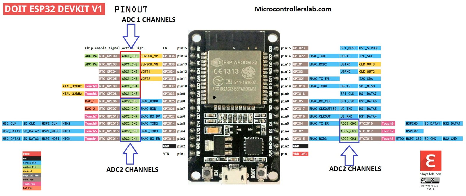
Both these ADCs support up to 18 analog channels which means we can connect eighteen analog sensors at a time with this board. But ADC2 is shared between other resources of this development board. So we have two ADCs in ESP32 ADC1 and ADC2. Pin mapping of ADC channels for both ADCs is shown below.
ESP32 ADC1 Pin Mapping
Following is a pin mapping of with ESP32 devkit DOIT board. Although ESP32 chip ADC1 has eight channels, the Devkit DOIT board supports only 6 channels. But still, we have enough analog channels for analog sensor interfacing.
- ADC1_CH0 >>>GPIO36
- ADC1_CH1 >>>Not available on this board Devkit DoIT ( 30 pins version )
- ADC1_CH2 >>> NA
- ADC1_CH3 >>>GPIO39
- ADC1_CH6 >>>GPIO34
- ADC1_CH7 >>> GPIO35
- ADC1_CH4 >>> GPIO32
- ADC1_CH5 >>> GPIO33
ESP32 ADC2 Pin Mapping
Pin mapping for ADC2 channel is given below. Devkit DOIT board ADC2 supports 10 analog channels and all these analog channels are available on Devkit do it board.
- ADC2_CH0 >>>GPIO0
- ADC2_CH1 >>> This channel is not available on Devkit DOIT board
- ADC2_CH2 >>>GPIO2
- ADC2_CH3 >>> GPIO15
- ADC2_CH4 >>> GPIO13
- ADC2_CH5 >>> GPIO12
- ADC2_CH6 >>>GPIO14
- ADC2_CH7 >>> GPIO27
- ADC2_CH8 >>> GPIO25
- ADC2_CH9 >>> GPIO26
Although we have 10 analog channels available in ADC2, all these channels are shared among other resources. For example, ADC2 is shared with WiFi drivers, therefore you can only use it after WiFi drivers are not started. You have to make your program smart enough to switch between two resources. The easy way is to turn off the WiFi driver when you want to use ADC2 and read the analog value and after that turn on the WiFi driver when you want to update value to the server etc. I will explain more about it in later parts of this series of tutorials. The figure below shows the pins of analog channels on Devkit DOIT:
How to use Analog to digital converter channels of ESP32
Now, let’s see how to write code or program for reading ADC values of with any of these 15 channels available on this board. After that, we will see an example, where we connect a variable resistor with the analog channel and measure voltage and display it on the serial monitor of Arduino IDE. ESP32 analog channels are of 12 bit which means the minimum step of each voltage level is between 0 and 4095. Analog channel produces a digital value between 0 and 4095 according to the voltage at the input of the analog channel. For example
- If the voltage is 0 at the input of the analog channel, the digital value will be zero.
- If the voltage is 3.3 volt at the input, the digital value will be 4095. So the maximum voltage limit is 3.3 volt.
- But we can measure higher voltage else by using voltage step down methods like voltage divider method, step down transformer method in case of ac voltage measurement.
You may like to check our previous project on high voltage measurement with other microcontrollers. Although a different microcontroller is used in these projects, you can apply the same concepts to ESP32 ADC for measurement of current, voltage, power factor and ac power.
- Alternating current measurement using pic microcontroller
- AC voltage measurement using pic microcontroller
- How to measure ac voltage with Arduino
- Current sensor interfacing with Arduino
- AC power measurement using pic microcontroller
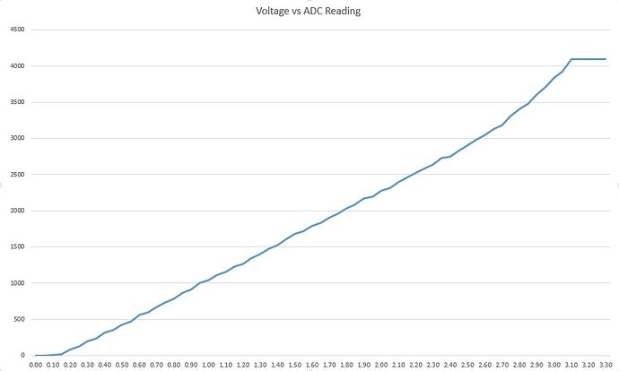
One main disadvantage of ESP32 ADC is that it has a non linear behavior. Graph below shows its non-linear curve. you can find more information about it on this link.
Program for ESP32 Analog to digital converter
So we are using Arduino IDE in these tutorials. Arduino IDE provides a built-in function to read analog values that are analogRead function.
- analogRead(analog_pin_number) : We will use this function to read analog value. This analogRead function has only one argument which is a pin number of the analog channel you want to use. I have already provided pin mapping of all analog channels with GPIO pins above. So you will only pass the name of GPIO pin to this function like analogRead(36), it will read the value from ADC1 channel zero. The figure above also shows the pin number and respective analog channels.
- You just need to store the output of this function in any variable other than character types. Because the character type variable can store values between 0 and 255 only.
ESP32 ADC Useful Arduino Functions
These functions are used to set various parameters of ESP32 ADC pins such as resolution, attenuation, setting reference voltage, etc.
void analogReadResolution(uint8_t bits)
This function sets the resolution of analogRead return values. Default is 12 bits (range from 0 to 4096). If between 9 and 12, it will equal the set hardware resolution, else the value will be shifted. The range is between 1 – 16.
void analogSetWidth(uint8_t bits)
The analogSetWidth function sets the sample bits and analog read resolution. By default, it is 12bit (0 – 4095) and the range is between 9 – 12.
void analogSetClockDiv(uint8_t clockDiv)
This method selects the divider for the ADC clock. By default, it is 1 and the range is between 1 – 255.
void analogSetAttenuation(adc_attenuation_t attenuation)
The analogSetAttenuation() function sets the attenuation for all ADC channels. By default, it is 11db. Also, the attenuation can be one of these values:
typedef enum {
    ADC_0db,
    ADC_2_5db,
    ADC_6db,
    ADC_11db
} adc_attenuation_t;| Attenuation | Measurable input voltage range |
|---|---|
ADC_ATTEN_DB_0 | 100 mV ~ 950 mV |
ADC_ATTEN_DB_2_5 | 100 mV ~ 1250 mV |
ADC_ATTEN_DB_6 | 150 mV ~ 1750 mV |
ADC_ATTEN_DB_11 | 150 mV ~ 2450 mV |
int hallRead()
The hallRead() function is used to get value for the HALL sensor (without LNA). Hall Sensor output is connected to pins 36(SVP) and 39(SVN)
void analogSetVRefPin(uint8_t pin)
The analogSetVRefPin() function sets the pin to use for ADC calibration or to set a reference voltage for ADC if the esp is not already calibrated (25, 26, or 27). You can use reference voltage on 25, 26, and 27 pins.
If you are just getting started with ESP32 programming, check these earlier tutorials:
- step to install ESP32 library in Arduino IDE
- ESP32 Pin mapping
- ESP32 GPIO pins with LED blinking example
- ESP32 push button interfacing
Now make this circuit diagram on your bread board and after that, we will write a code to measure voltage using a variable resistor.

In the above circuit diagram, a variable resistor is used. one terminal of the variable resistor is connected with the ground, and another terminal with 3.3 volts. The Center terminal of the variable resistor is connected with GPIO15 which is ADC2 channel three or ADC2_CH3.
Code for analog voltage measurement using ESP32 ADC
Code for analog voltage measurement is shown below. All the functions used in this code have already explained in the previous tutorial and in this tutorial except serial.begin() and serial.println() functions.
const int Analog_channel_pin= 15;
int ADC_VALUE = 0;
int voltage_value = 0;
void setup()
{
Serial.begin(115200);
}
void loop()
{
ADC_VALUE = analogRead(Analog_channel_pin);
Serial.print("ADC VALUE = ");
Serial.println(ADC_VALUE);
delay(1000);
voltage_value = (ADC_VALUE * 3.3 ) / (4095);
Serial.print("Voltage = ");
Serial.print(voltage_value);
Serial.print("volts");
delay(1000);
}
Now I will explain the working of code line by line. In these lines, first we give a name to ADC2_CH3 as Analog_channel_pin and after that, we initialized two integer variables to zero. One variable is used to store digital value and other variable is used to store voltage.
const int Analog_channel_pin= 15;
int ADC_VALUE = 0;
int voltage_value = 0;
In the setup() function, we have serial.begin function is used to initialize serial communication of esp32 and serial communication rate is defined by baud rate. So we have initialized the baud rate of 115200. Serial communication will be used to send data from ESP32 board to serial monitor of Arduino IDE.
Serial.begin(115200);Now the main function of this code is a loop part where we are taking an analog input and displaying it on serial monitor of Arduino IDE with the help of these lines. serial.print function is used to transmit data without a new line at the end and serial.println() function is also used to transmit data but it also includes new line character at the end of the string. After that delay function is used to add a delay of one second. It is not necessary to add delay but we did it check to receive value after every one second.
ADC_VALUE = analogRead(Analog_channel_pin);
Serial.print("ADC VALUE = ");
Serial.println(ADC_VALUE);
delay(1000);
Now in the last part, the first line will convert the digital value of ADC_VALUE into voltage. ADC_VALUE is multiplied with a resolution of ESP32 ADC which is 3.3 / 4095. Resolution is also know as a minimum step of adc for each corresponding value of voltage. For example, if ADC_VALUE counts 10, its mean it has taken 10 steps or value at the input pin is 10 times the resolution of adc. So to convert ADC_VALUE back into voltage we simply multiply it with resolution as we done in the first line. After that Serial.print function sends a string of “voltage = ” and then voltage value and after that unit of voltage is transmitted to the serial monitor.
voltage_value = (ADC_VALUE * 3.3 ) / (4095);
Serial.print("Voltage = ");
Serial.print(voltage_value);
Serial.print("volts");
delay(1000);
So when you run this code on ESP32 board, you will get the value of adc and voltage value after every one second on serial monitor of Arduino IDE.
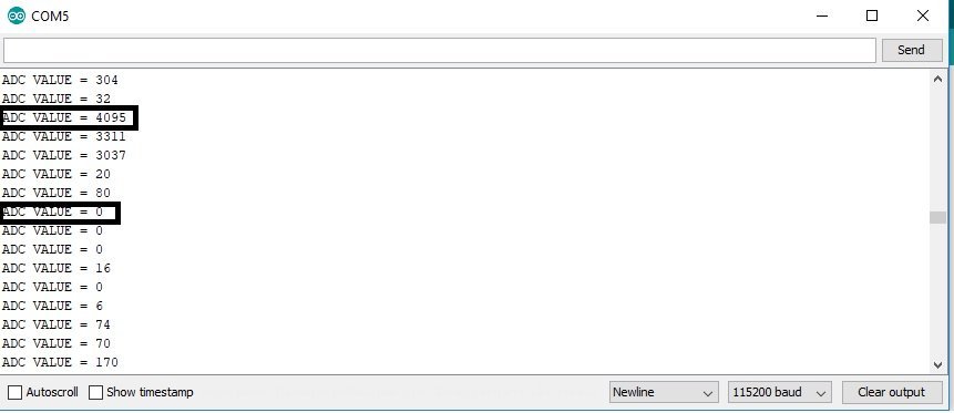
Display ADC and Voltage on OLED with ESP32
In the previous section, we have seen how to convert an analog signal into a digital value using ESP32 in Arduino IDE. Similarly, we can also convert the measured digital value back into voltage by multiplying digital value with the resolution of ADC which is 3.3/4095 for 12-bit resolution of ESP32. Now let’s see an example to measure analog voltage signal with ESP32.
In this section, we will see how to display analog voltage values on a 0.96 SSD1306 OLED display using ESP32 and Arduino IDE.
You can read this in-depth guide on OLED interfacing with ESP32:
OLED Display Interfacing with ESP32 – Display Text, Draw shapes and Images
Installing OLED Libraries in Arduino IDE
To use the OLED display in our project, we have to install the Adafruit SSD1306 library and Adafruit GFX library in Arduino IDE. Follow the steps below to successfully install them.
Open Arduino IDE and click on Sketch > Library > Manage Libraries. Type ‘SSD1306’ in the search tab and install the Adafruit SSD1306 OLED library.

We will also require the Adafruit GFX library which is a dependency for SSD1306. Type ‘Adafruit GFX’ in the search tab and install it as well.
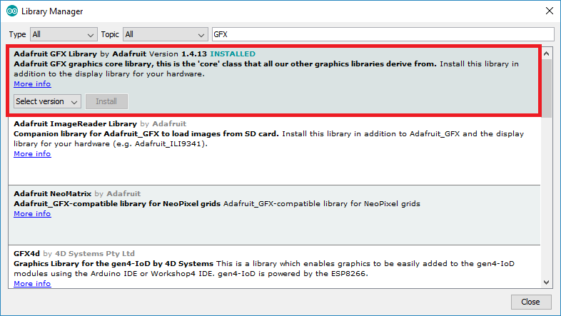
After installing the libraries, restart your IDE.
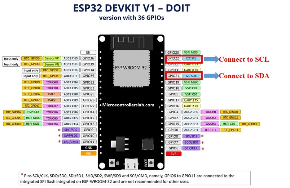
ESP32 I2C Pins
The I2C pins stated above are set in default. If we want to change the GPIO pins we have to set them in code. The diagram below shows the pinout for the ESP32.
Note: If we use other GPIO pins of ESP32 for I2C communication, we can define other pins inside our Arduino sketch. We don’t have to use default I2C pins.
You can learn more about I2C communication here:
I2C Communication Introduction
Connection Diagram– OLED with ESP32 and Potentiometer
Required Components:
- ESP32 board
- Potentiometer
- 0.96-inch SSD 1306 OLED Display
- Breadboard
- Connecting Wires
As you can see above, we have connected all the VCC terminal of OLED with a Vin pin of ESP32. The SCL terminal of the OLED is connected with GPIO22 and the SDA terminal of the OLED is connected with the GPIO21 pin of ESP32. The grounds of all three devices are common.
| ESP32 board | SSD1306 OLED Display |
|---|---|
| Vin | VCC |
| GPIO21(I2C SDA) | SDA |
| GPIO22(I2C SCL) | SCL |
| GND | GND |
The I2C pins stated above are set in default. If you want to use any GPIO pins for I2C, you will have to set it in code using SoftI2C().
Assemble the circuit as shown in the schematic diagram below:

As you can see above, the middle pin of the potentiometer is connected with D15 pin of ESP32 board. Other terminals such as left and right are connected to 3.3V and GND pins, respectively.
Arduino Sketch (Displaying ADC and Voltage Readings on OLED Display)
Open your Arduino IDE and go to File > New. A new file will open. Copy the code given below in that file and save it.
This sketch will display the ADC values and the corresponding analog voltage on the Serial Monitor as well as on the OLED.
#include <Adafruit_GFX.h>
#include <Adafruit_SSD1306.h>

const int ADC_pin = 15;
int sensor_reading = 0;
float analog_voltage;

Adafruit_SSD1306 display = Adafruit_SSD1306(128, 64, &Wire, -1);

void setup() {
  Serial.begin(115200);

   if(!display.begin(SSD1306_SWITCHCAPVCC, 0x3C)) {
  Serial.println(F("SSD1306 allocation failed"));
  for(;;);}
  delay(2000);
display.clearDisplay();
display.setTextColor(WHITE);
}

void loop() {
  display.setCursor(0,0);
  display.setTextSize(1);
  display.clearDisplay();

  sensor_reading = analogRead(ADC_pin);
  Serial.print("ADC reading = ");
  Serial.println(sensor_reading);
  analog_voltage = sensor_reading * 3.3 / 4095;
  Serial.print("Volatge reading = ");
  Serial.println(analog_voltage);


  display.setTextSize(1);
  display.setCursor(0,0);
  display.print("ADC reading: ");
  display.setTextSize(2);
  display.setCursor(0,10);
  display.print(sensor_reading);

  display.setTextSize(1);
  display.setCursor(0,35);
  display.print("Voltage: ");
  display.setTextSize(2);
  display.setCursor(0,45);
  display.print(analog_voltage);
  display.print(" ");
  display.setTextSize(2);
  display.setCursor(60,45);
  display.print("V");

  Serial.println();
  display.display();
  delay(1000);

}
How the Code Works?
Firstly, we will include the OLED libraries that we previously installed for the proper functionality of the OLED display.
#include <Adafruit_GFX.h>
#include <Adafruit_SSD1306.h>
Secondly, we will define three variables. One will hold the ADC pin GPIO15 that we will connect with the potentiometer. The second one will be called ‘sensor_reading’ and will save the ADC values. It is initially set to 0. For the third variable, we will define it as a floating type to save the values for the analog voltage.
const int ADC_pin = 15;
int sensor_reading = 0;
float analog_voltage;
Now, we will create an object named display which will be handling the OLED display and specifying the width, height, I2C instance (&Wire), and -1 as parameters inside it.’ -1′ specifies that the OLED display which we are using does not have a RESET pin. If you are using the RESET pin then specify the GPIO through which you are connecting it with your development board.
Adafruit_SSD1306 display = Adafruit_SSD1306(128, 64, &Wire, -1);Inside the setup() function, we will open the serial communication at a baud rate of 115200.
void setup() {
  Serial.begin(115200);
}
Moreover, we will also initialize the OLED display by using display.begin(). Make sure you specify the correct address of your display. In our case, it is 0X3C.
if(!display.begin(SSD1306_SWITCHCAPVCC, 0x3C)) {
  Serial.println(F("SSD1306 allocation failed"));
  for(;;);}
Then, we will clear the buffer by using clearDisplay() on the Adafruit_SSD1306 object. Additionally, we will set the colour of the text as white.
display.clearDisplay();
display.setTextColor(WHITE);
Now, inside the infinite loop() function, we will set the position of the cursor of the OLED and also set the text size. The clearDisplay() function will wipe off the previous readings from the display after each loop() so that new ones can be printed.
  display.setCursor(0,0);
  display.setTextSize(1);
  display.clearDisplay();
Obtaining ADC and Voltage Readings
Then we will first find out the ADC value according to the varying voltage using analogRead(). We will pass the ADC pin connected to the potentiometer as an argument inside it. This will be stored in the integer variable we defined previously ‘sensor_reading.’
sensor_reading = analogRead(ADC_pin);Next, we will print these readings in the serial monitor after every 1 second.
Serial.print("ADC reading = ");
Serial.print(sensor_reading);
Next we will calculate the analog voltage we multiplying the ADC digital value with a resolution of ESP32 ADC which is 3.3/4095. It will provide output in the form of voltage.
 analog_voltage = sensor_reading * 3.3 / 4095;
  Serial.print("Volatge reading = ");
  Serial.println(analog_voltage);
Displaying Text on OLED
Now, we will display these two readings on the OLED display. First, we will set the size of the text using setTextSize() and pass the size as a parameter inside it. 1 denotes the smallest size and it increases relatively after incrementing it. We have set the font size as ‘1’ for the headings and ‘2’ for the actual values. Whenever we increase the size by +1, the pixel resolution of the text increases by 10 in height.
We will use the setCursor() function to denote the x and the y axis position from where the text should start. We have passed (0,0) as the parameter hence the text starts from the upper left corner. The first parameter is the x-axis position that (+x) increases towards the right. The second parameter is the y-axis position that (+y) increases downwards. We will set the cursor to new positions for each text.
Then by using println() we will pass the text which we want to display on the OLED. Just specify it like you do when printing strings/variables of serial objects.
Finally, we will call the display() function on the display object so that the text displays on the OLED.
display.setTextSize(1);
  display.setCursor(0,0);
  display.print("ADC reading: ");
  display.setTextSize(2);
  display.setCursor(0,10);
  display.print(sensor_reading);

display.setTextSize(1);
  display.setCursor(0,35);
  display.print("Voltage: ");
  display.setTextSize(2);
  display.setCursor(0,45);
  display.print(analog_voltage);
  display.print(" ");
  display.setTextSize(2);
  display.setCursor(60,45);
  display.print("V");

  Serial.println();
  display.display();
  delay(1000);
Demonstration
Choose the correct board and COM port before uploading your code to the ESP32 board. Go to Tools > Board and select ESP32 Dev Module.
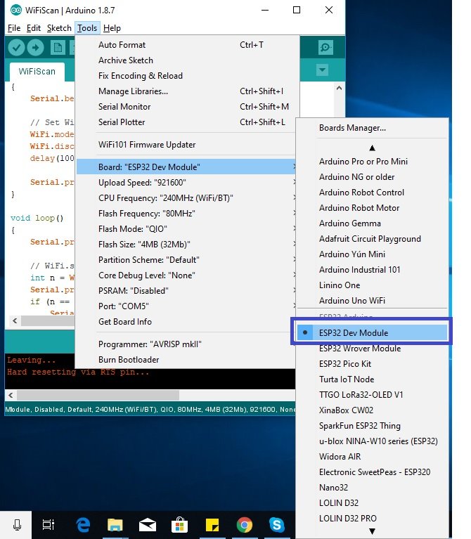
Next, go to Tools > Port and select the appropriate port through which your board is connected.

Now click on the upload button to upload code to ESP32. After that open the Arduino serial monitor and press the enable button on ESP32:

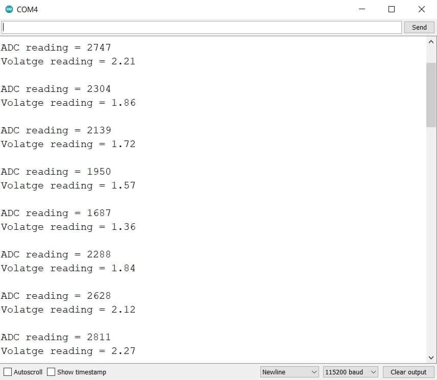
The OLED display will start showing values for ADC and its corresponding voltage in volts. Rotate the knob of the potentiometer and see the values changing from 0-1023 for ADC and 0-3.3V for voltage.

Open the serial monitor and set the baud rate to 115200. You will be able to see all the different ADC and voltage readings as you rotate the knob of the potentiometer.
Conclusion
In conclusion, we have learned about ESP32 ADC and how to get readings of both ADC and analog voltage using Arduino IDE. We used a potentiometer to supply varying voltage to the ESP32 ADC GPIO15 pin and then read the signal obtained. Likewise, we were also able to display the readings on an OLED display.
You can also check ESP32 Webserver tutorial.
We have similar guide with MicroPython here:
works perfect, thank you
Hello,
Your tutorial about ESP32 ADC http://microcontrollerslab.com/adc-esp32-measuring-voltage-example/ is really interesting, as well as other ESP32 articles, thanks.
For using ADC2 while WiFi activated, you said: “I will explain more about it in later parts of this series of tutorials.”. Have you done this and where? I can’t find it.
I’m using ESP32-Cam board where ADC1 is not available, and WiFi is activated so I can’t measure voltage with ADC2…
In https://github.com/espressif/arduino-esp32/issues/102 a “fix” seems to allow using ADC2 while WiFi activated, but no explanation about the consequences on WiFi and why WiFi modifies ADC2 configuration… This fix seems to work for me, whereas switching WiFi off for reading ADC2 doesn’t.
So if you have more informations about how to do it in a safe way, let me know please.
Regards,
Marc
Hi Marc,
asper my understanding, the Wi-Fi driver may be using the ADC2 to measure the signal strength received from the Antenna, in order to determine the RSSI.
Regards
Chary BS
you saved me a lot of time thank you
I fixed your example code for you
“`
const int Analog_channel_pin= 15;
int ADC_VALUE = 0;
double voltage_value = 0;
void setup()
{
Serial.begin(115200);
}
void loop()
{
ADC_VALUE = analogRead(Analog_channel_pin);
Serial.print(“ADC VALUE = “);
Serial.print(ADC_VALUE);
voltage_value = (ADC_VALUE * 3.3 ) / (4095);
Serial.print(” | Voltage = “);
Serial.print(voltage_value);
Serial.println(“volts”);
delay(1000);
}
“`
yeah. Was wondering. Float and integer multiplication okay but the result has to be float at least. Double is even better
Hi,How will I setup the step of adc for each corresponding value of voltage?Has it have a special flag or
a special hardware?
useful
How many ADC pins are there in an ESP32?
Interesting tutorial – thanks. I am trying to connect an RFID RMD6300 to and ESP32 (TTG0 T8). On the arduino uno I connect the RMD6300 TX cable to the ~6 pin and the RX cable to the 8 pin and it works perfectly. I am trying to work out what the equivalent pins would be on the ESP32. Can you help?
Hi,
You can find information on UART pins of ESP32 on this link:
http://microcontrollerslab.com/esp32-pinout-use-gpio-pins/
Hello I need to measure the 0-30 V or 0-48V. Do you have some example or module that measure upper 25V? Thanks
Hi, You just need tp step down the voltage to a limit less than 3.3V using a voltage divider and then use voltage divider factor in code.
Thank you very much!!
Hi guys,
I very curious about the relationship between input voltage and measurable voltage. The Input voltage range is 0-3.3V and by default the measurable voltage is 150mV-2450mV (11db). Why the voltage measure is 0-3.3V, not should be 2.45V? And when change the attenuation to 6db or others the maximum voltage measurable will become the what stated here. Got any body know why? Thanks a lot.
Hi guys,
I am wonder about the relationship between input voltage range and measurable voltage range that from attenuation setting. By default, the attenuation was set to 11db and the measurable voltage range is from 150mV ~ 2450mV. Why on demonstration here, the voltage measure can up to 3.3V(Since, the analog reading is 2800 while)? but if set to other db, then the range will follow what stated on measurable input voltage range. Anybody who know this can answer me? Thanks a lot.
How to read voltage within the range of 5volt
(if analog signal is of range between 0 to 5 volt then how to read it using ESP 32)
In the first example, I changed the voltage_value from an int to a float.
Also, unrelated, the ESP32-S2 has a 13 bit ADC, so my constant became 8191.
Still working with the multiplier for my 1M/100k voltage divider.
Good day. He has such a specific problem. When I connect ESP32 6 sensors to ADC1, I always get only 3 values. The next 3 values are OVF. When I use more than 3 ADC1, it is always on the fourth OVF. I’ve tried absolutely everything. It doesn’t matter which ADC1 pins you use. Don’t know what to do with it? Thank you.
Hi,
Can anyone confirm whether the Arduino API uses the calibration value (vRef in eFuse) in its analogRead() or analogReadMillivolts() or if this needs to be done in post-processing in code?
My suspicion is it doesn’t but would love it if someone had knowledge or had tested it somehow.
Thanks