In this tutorial, we will learn to design a VI that will display the number on a seven-segment LED display. We will provide a constant value as input, and at VI, we will display the entered constant on a seven-segment display. Using all the knowledge we have gained so far, we will be designing a simple VI as a sample project in this tutorial. At the end of the tutorial, you are provided with an exercise to do by yourself, and in the next tutorials, we will assume that you have done those exercises and not explain the concept regarding them.
Introduction to Seven-Segment Display
The seven-segment display is a device that we use for displaying numeric information. This device consists of seven individual LED segments arranged in the shape of the digit “8”. This can represent numerals from 0 to 9, as well as some letters and symbols, by lighting segments in various combinations. Each segment corresponds to a specific part of the digit, and by selectively turning on or off these segments, we can form various characters. Seven-segment displays find extensive application in digital clocks, calculators, measurement instruments, and any scenario where numerical information needs to be visually conveyed.
Seven-Segment Display Example in LabVIEW
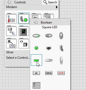
Create a blank VI as we did in Tutorial 1 and save it for future use. On the Front Panel, press right-click, and from the Control Palette that just appeared, select Boolean and then select Square LED, as shown in the figure below.
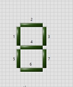
Place seven such LEDs and adjust their sizes so that they look like a seven-segment display. For those who are not familiar with the shape of a seven-segment display, see the figure below. Here, we have placed 7 LEDs in the shape of a seven-segment display.
Case Structure Placement
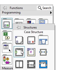
Now on the block diagram window, press right-click, and from the Function Palette, select Structures, and then select Case Structures, as shown in the figure below.
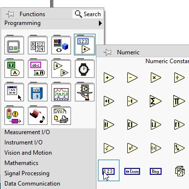
Drag it over some portion of the block diagram window. By default, the cases of a case structure are set to true and false, but in our case, we need them to be numeric cases, i.e., 0, 1, 2,… 9. This is because we are interested in displaying numbers on LEDs. From the Function Palette, select Numeric and then select Constant, as shown in the figure below.
Numeric Condition
Connect this constant to the case selector node of the case structure, as shown in the figure below.

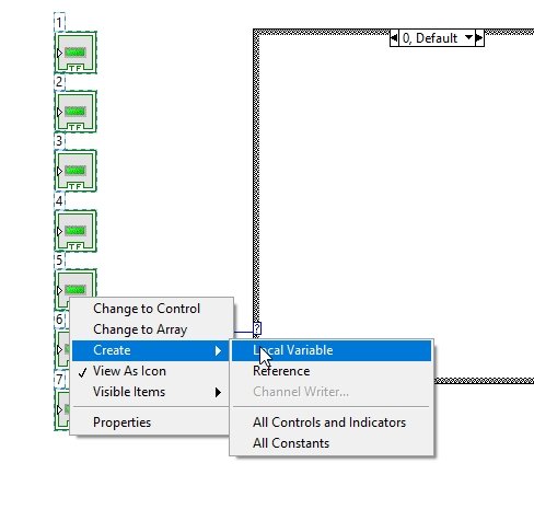
This will change the type of the case structure’s cases from Boolean to numeric, as we will see shortly. On the block diagram, select all the respective blocks of 7 LEDs, used previously on the front panel for the creation of the 7-segment display and click right after selecting the blocks. From the dropdown menu, select Local Variables, as shown in the figure below.
Case Structure
This will create 7 local variables with 7 LEDs. Place them inside case 0 of the case structure, as shown in the figure below.

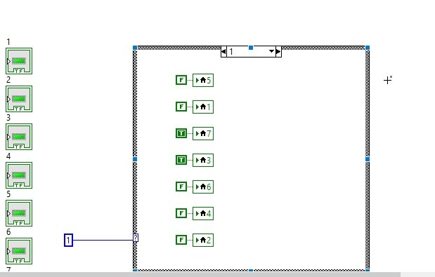
Now from the above window, at the top of the case structure, select 1. It will allow us to design a block diagram that should be implemented when the input numeric value is 1. Again, copy all the LED blocks and create 7 local variables as we have done before, and place them all in the case 1 block of case structures as shown in the figure below.
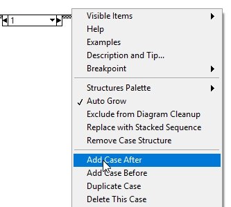
Now to add a case for the remaining numbers, click right on the boundary of the case structure, and from the drop-down menu select Add case after, as shown in the figure below.
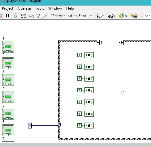
This will add a case after 1, i.e., case 2. Again, create local variables for all the LEDs and place them inside the case 2 block. Do the same for all the remaining digits up to 9. Now open case 0 and right-click on the local variable in it. From the dropdown, select Create and then select Constant, as shown in the figure below.

Constants of Case Structure
This will create a Boolean constant at the input of the LED block. Do the same with all the remaining LED blocks in case 0, as shown in the figure below.

Now move to case 1 and create a constant for every Boolean LED’s local variable already present in that case, as shown in the figure below.
Do the same with all the 10 cases of LEDs we created before.
Now, from the seven-segment arrangement we designed earlier in this tutorial, draw a pattern of LEDs that need to be turned on in case 0. i.e., for case 0, the input will be 0, and the seven segments must display 0 using the LEDs. To do so, all LEDs except 4 in the display should be turned on. Hence, except for 4, make all the constants on the remaining LEDs true, as shown in the figure below.
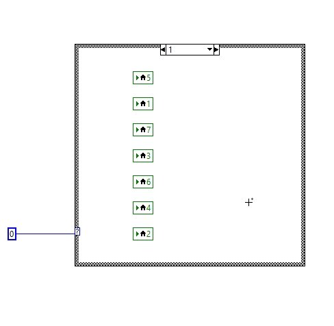
For case 1, only LEDs 3 and 7 should be on, and all the remaining LEDs should be off, so the corresponding pattern of LEDs is shown in the figure below.
Do the same for case 2. Turn on LEDs 2, 3, 4, 5, and 6 and keep the remaining LEDs off as shown in the figure below.

Output as Seven-Segment Display
Repeat the same with all the remaining digits as we have done for 0, 1, and 2, and now run the VI, changing the input constant to the case selector constant as shown in the figure below.

The selected pattern for the case of input variable 9 is displayed on the seven-segment LED pattern, as is obvious from the above figure.
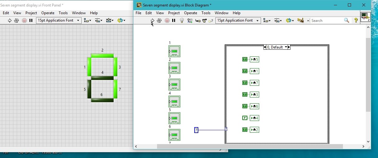
Try another input constant, i.e., 7, as an example; this will display 7 in the seven-segment display output as shown in the figure below.
Exercise
- Run a loop and display all the digits from 0 to 9 on the seven-segment with a time difference of 1 sec between two consecutive digits, and at the end of the loop display a loop completion message.
Conclusion
In conclusion, this tutorial provided a comprehensive and in-depth overview of using seven-segment displays in LabVIEW’s VI. This also improves the understanding of case structures and how to manipulate them according to the situation. This article provides a step-by-step procedure to create a functional seven-segment display with the help of an example. You can utilize this tutorial to build a custom application using seven-segment displays as numeric indicators. To reinforce the concept of seven-segment displays, we have also provided an exercise at the end. We hope this tutorial was helpful in broadening your knowledge of LabVIEW.
You may also like to read:
- MPU6050 with Raspberry Pi Pico (Accelerometer, Gyroscope, and Temperature)
- Install ESP32 Filesystem Uploader in Arduino IDE – SPIFFS
- Get Epoch/Unix time with ESP32 through NTP server using Arduino IDE
- ESP32 Real Time Clock (RTC) using DS3231 Module and display on OLED
- STM32 Blue Pill Timer in PWM Mode with LED Dimmer Example
This concludes today’s article. If you face any issues or difficulties, let us know in the comment section below.