In this tutorial, we will learn how to use the MPU6050 MEMS module with Raspberry Pi Pico to measure accelerometer, gyroscope, and temperature values using MicroPython firmware. First, we will look at the MPU6050 introduction, including its pinout diagram and pin configuration. Second, we will see how to upload the MPU6050 MicroPython library to Raspberry Pi Pico using Thonny IDE. Finally, we will learn how to read accelerometer, gyroscope, and temperature values from the MPU6050 module with Raspberry Pi Pico.
Recommended Components
The following components are used in this project or are helpful for getting started with Raspberry Pi Pico development.
| Component | How it’s used in this project | Buy on Amazon |
|---|---|---|
| Raspberry Pi Pico | The RP2040 microcontroller board used in this tutorial. | Check Price |
| MPU6050 Module | 6-axis accelerometer and gyroscope module read in this tutorial. | Check Price |
| Breadboard | Solderless breadboard for building the circuit. | Check Price |
| Jumper Wires | Male-to-male / male-to-female wires for the connections. | Check Price |
As an Amazon Associate we earn from qualifying purchases. Prices and availability are accurate as of the date/time indicated and are subject to change.
Prerequisites
Before starting this lesson, make sure you are familiar with Python 3 and have it installed on your system. You should also have MicroPython set up on your Raspberry Pi Pico and a working Integrated Development Environment (IDE) for programming. We will use Thonny IDE throughout this tutorial, as we have done in previous guides for blinking and controlling LEDs:
If you are using uPyCraft IDE, refer to this guide:
MPU6050 Sensor Module Introduction
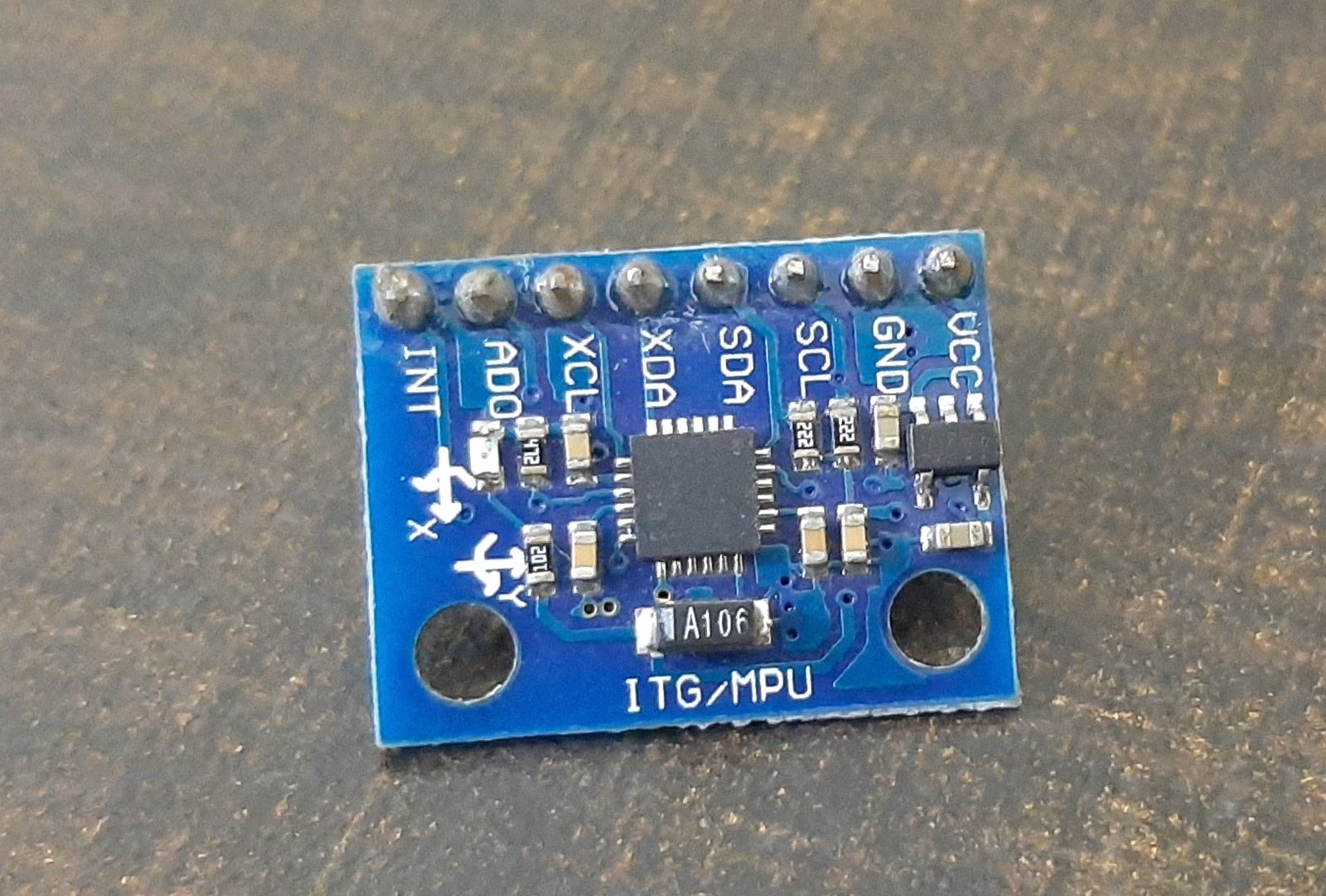
The MPU6050 is a MEMS (Micro-Electro-Mechanical System) sensor module built around InvenSense’s MPU6050 IC. This chip integrates a three-axis gyroscope, a three-axis accelerometer, and a digital motion processor (DMP) into a single IC package. It also includes an onboard temperature sensor. All of these components are fabricated on the same die, making the MPU6050 a highly compact and versatile inertial measurement unit (IMU).
The MPU6050 can be used to measure velocity, acceleration, orientation, angular displacement, and other motion-related parameters. It is the same type of sensor found in modern smartphones and game controllers. The sensor provides a complete six-axis motion-tracking solution and is widely used in robotics, drone flight controllers, gesture recognition systems, and wearable devices.
One of the most important features of the MPU6050 is its powerful Digital Motion Processor (DMP). The DMP handles complex calculations internally, such as sensor fusion and quaternion computation, before making processed data available on the I2C bus. This offloads significant processing work from the host microcontroller, which is especially useful in resource-constrained systems like the Raspberry Pi Pico.
MPU6050 Key Specifications
Understanding the technical specifications of the MPU6050 helps you choose the right settings for your application. Here are the key specifications:
- Supply Voltage: 2.375V to 3.46V (on-chip regulator supports 5V input via the module’s regulator)
- Accelerometer Range: ±2g, ±4g, ±8g, or ±16g (user-selectable)
- Gyroscope Range: ±250, ±500, ±1000, or ±2000 degrees per second (user-selectable)
- Temperature Sensor Range: -40°C to +85°C
- I2C Bus Speed: Up to 400 kHz (Fast Mode)
- I2C Address: 0x68 (AD0 low) or 0x69 (AD0 high)
- Output Data Rates: Programmable from 4 Hz to 1000 Hz (with DLPF enabled)
I2C Output Interface
The MPU6050 communicates with the host microcontroller via the I2C bus. This allows us to transfer three-axis accelerometer and three-axis gyroscope data to the Raspberry Pi Pico using just two data lines: SDA and SCL. Each sensor value is stored at a specific register address inside the MPU6050, and the host controller reads these addresses to retrieve individual measurements such as acceleration, gyroscope, and temperature.
One significant advantage of I2C is that multiple devices can share the same bus. By using the AD0 pin to change the I2C address, you can connect two MPU6050 modules to a single Raspberry Pi Pico simultaneously — one at address 0x68 and the other at 0x69.
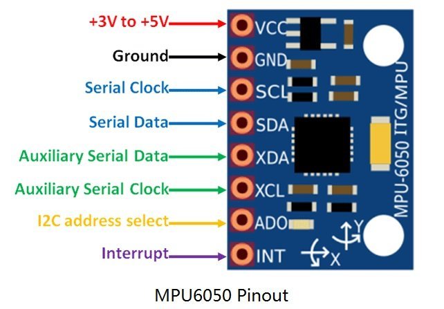
MPU6050 Pinout
Although the MPU6050 IC itself has 24 pins, only 8 pins are exposed on the breakout module. These 8 pins handle power supply, I2C communication, address selection, auxiliary I2C bus connections, and interrupt signaling.
Pin Descriptions
- VCC: Power supply pin. Accepts 3V to 5V DC. Most breakout modules include a voltage regulator, allowing you to power the module directly from a 5V source while the IC operates at 3.3V.
- GND: Ground pin. Connect to the ground of your microcontroller and power supply.
- SCL (Serial Clock): I2C clock line. Connect to the SCL pin of your Raspberry Pi Pico. The Pico acts as the I2C master and drives the clock signal.
- SDA (Serial Data): I2C data line. Used to transfer sensor data bidirectionally between the MPU6050 and Raspberry Pi Pico.
- XDA (Auxiliary SDA): Optional auxiliary I2C data pin, used to connect external sensors such as a magnetometer directly to the MPU6050 for sensor fusion operations.
- XCL (Auxiliary SCL): Optional auxiliary I2C clock pin for the same purpose as XDA.
- AD0 (Address Select): Sets the I2C slave address. When this pin is pulled LOW (default), the address is 0x68. When pulled HIGH, the address becomes 0x69. This allows two MPU6050 modules on the same bus.
- INT (Interrupt): Digital output pin that signals the microcontroller when new sensor data is ready to be read. Useful for interrupt-driven data acquisition instead of continuous polling.
Interface MPU6050 with Raspberry Pi Pico
To interface the MPU6050 with Raspberry Pi Pico, you only need the first four pins: VCC, GND, SCL, and SDA. The auxiliary and interrupt pins are optional and not required for basic operation.
Raspberry Pi Pico I2C Pins
Raspberry Pi Pico has two I2C controllers: I2C0 and I2C1. Both are accessible through multiple GPIO pins, giving you flexibility in wiring. You must configure the desired GPIO pins in software before using an I2C controller.
| I2C Controller | GPIO Pins |
| I2C0 – SDA | GP0/GP4/GP8/GP12/GP16/GP20 |
| I2C0 – SCL | GP1/GP5/GP9/GP13/GP17/GP21 |
| I2C1 – SDA | GP2/GP6/GP10/GP14/GP18/GP26 |
| I2C1 – SCL | GP3/GP7/GP11/GP15/GP19/GP27 |
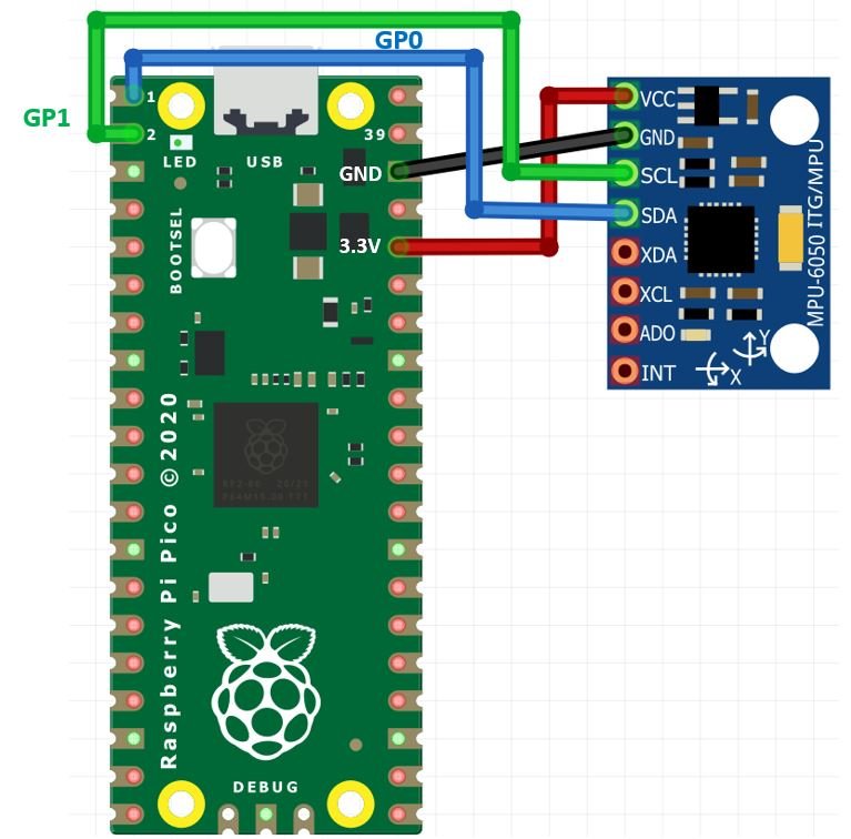
The wiring connections used in this tutorial are:
| MPU6050 | Raspberry Pi Pico |
| VCC | 3.3V |
| SDA | GP0 (I2C0 SDA) |
| SCL | GP1 (I2C0 SCL) |
| GND | GND |
The VCC pin of the MPU6050 is connected to the 3.3V output of the Raspberry Pi Pico. The GND pins of both devices share a common ground. The SCL pin of the MPU6050 connects to GP1 (I2C0 SCL), and the SDA pin connects to GP0 (I2C0 SDA).
You may also use other valid SDA/SCL pin combinations from the table above, as long as you update the pin numbers accordingly in the MicroPython code.

MPU6050 MicroPython Libraries
This project requires two MicroPython library files: imu.py and vector3d.py. These files implement the MPU6050 driver and a 3D vector utility class that the driver depends on. You need to copy both files to the Raspberry Pi Pico before running any example code.
To upload these libraries using Thonny IDE, open a new file, paste the library code, and save it to your Raspberry Pi Pico under the /lib folder with the exact filename (imu.py or vector3d.py). Saving libraries under /lib ensures MicroPython can find them automatically when your code imports them.
imu.py
# imu.py MicroPython driver for the InvenSense inertial measurement units
# This is the base class
# Adapted from Sebastian Plamauer's MPU9150 driver:
# https://github.com/micropython-IMU/micropython-mpu9150.git
# Authors Peter Hinch, Sebastian Plamauer
# V0.2 17th May 2017 Platform independent: utime and machine replace pyb

from utime import sleep_ms
from machine import I2C
from vector3d import Vector3d


class MPUException(OSError):
    pass


def bytes_toint(msb, lsb):
    if not msb & 0x80:
        return msb << 8 | lsb
    return - (((msb ^ 255) << 8) | (lsb ^ 255) + 1)


class MPU6050(object):
    _I2Cerror = "I2C failure when communicating with IMU"
    _mpu_addr = (104, 105)
    _chip_id = 104

    def __init__(self, side_str, device_addr=None, transposition=(0, 1, 2), scaling=(1, 1, 1)):
        self._accel = Vector3d(transposition, scaling, self._accel_callback)
        self._gyro = Vector3d(transposition, scaling, self._gyro_callback)
        self.buf1 = bytearray(1)
        self.buf2 = bytearray(2)
        self.buf3 = bytearray(3)
        self.buf6 = bytearray(6)
        sleep_ms(200)
        if isinstance(side_str, str):
            self._mpu_i2c = I2C(side_str)
        elif hasattr(side_str, 'readfrom'):
            self._mpu_i2c = side_str
        else:
            raise ValueError("Invalid I2C instance")
        if device_addr is None:
            devices = set(self._mpu_i2c.scan())
            mpus = devices.intersection(set(self._mpu_addr))
            number_of_mpus = len(mpus)
            if number_of_mpus == 0:
                raise MPUException("No MPU's detected")
            elif number_of_mpus == 1:
                self.mpu_addr = mpus.pop()
            else:
                raise ValueError("Two MPU's detected: must specify a device address")
        else:
            if device_addr not in (0, 1):
                raise ValueError('Device address must be 0 or 1')
            self.mpu_addr = self._mpu_addr[device_addr]
        self.chip_id
        self.wake()
        self.passthrough = True
        self.accel_range = 0
        self.gyro_range = 0

    def _read(self, buf, memaddr, addr):
        self._mpu_i2c.readfrom_mem_into(addr, memaddr, buf)

    def _write(self, data, memaddr, addr):
        self.buf1[0] = data
        self._mpu_i2c.writeto_mem(addr, memaddr, self.buf1)

    def wake(self):
        try:
            self._write(0x01, 0x6B, self.mpu_addr)
        except OSError:
            raise MPUException(self._I2Cerror)
        return 'awake'

    def sleep(self):
        try:
            self._write(0x40, 0x6B, self.mpu_addr)
        except OSError:
            raise MPUException(self._I2Cerror)
        return 'asleep'

    @property
    def chip_id(self):
        try:
            self._read(self.buf1, 0x75, self.mpu_addr)
        except OSError:
            raise MPUException(self._I2Cerror)
        chip_id = int(self.buf1[0])
        if chip_id != self._chip_id:
            raise ValueError('Bad chip ID retrieved: MPU communication failure')
        return chip_id

    @property
    def sensors(self):
        return self._accel, self._gyro

    @property
    def temperature(self):
        try:
            self._read(self.buf2, 0x41, self.mpu_addr)
        except OSError:
            raise MPUException(self._I2Cerror)
        return bytes_toint(self.buf2[0], self.buf2[1])/340 + 35

    @property
    def passthrough(self):
        try:
            self._read(self.buf1, 0x37, self.mpu_addr)
            return self.buf1[0] & 0x02 > 0
        except OSError:
            raise MPUException(self._I2Cerror)

    @passthrough.setter
    def passthrough(self, mode):
        if type(mode) is bool:
            val = 2 if mode else 0
            try:
                self._write(val, 0x37, self.mpu_addr)
                self._write(0x00, 0x6A, self.mpu_addr)
            except OSError:
                raise MPUException(self._I2Cerror)
        else:
            raise ValueError('pass either True or False')

    @property
    def sample_rate(self):
        try:
            self._read(self.buf1, 0x19, self.mpu_addr)
            return self.buf1[0]
        except OSError:
            raise MPUException(self._I2Cerror)

    @sample_rate.setter
    def sample_rate(self, rate):
        if rate < 0 or rate > 255:
            raise ValueError("Rate must be in range 0-255")
        try:
            self._write(rate, 0x19, self.mpu_addr)
        except OSError:
            raise MPUException(self._I2Cerror)

    @property
    def filter_range(self):
        try:
            self._read(self.buf1, 0x1A, self.mpu_addr)
            res = self.buf1[0] & 7
        except OSError:
            raise MPUException(self._I2Cerror)
        return res

    @filter_range.setter
    def filter_range(self, filt):
        if filt in range(7):
            try:
                self._write(filt, 0x1A, self.mpu_addr)
            except OSError:
                raise MPUException(self._I2Cerror)
        else:
            raise ValueError('Filter coefficient must be between 0 and 6')

    @property
    def accel_range(self):
        try:
            self._read(self.buf1, 0x1C, self.mpu_addr)
            ari = self.buf1[0]//8
        except OSError:
            raise MPUException(self._I2Cerror)
        return ari

    @accel_range.setter
    def accel_range(self, accel_range):
        ar_bytes = (0x00, 0x08, 0x10, 0x18)
        if accel_range in range(len(ar_bytes)):
            try:
                self._write(ar_bytes[accel_range], 0x1C, self.mpu_addr)
            except OSError:
                raise MPUException(self._I2Cerror)
        else:
            raise ValueError('accel_range can only be 0, 1, 2 or 3')

    @property
    def gyro_range(self):
        try:
            self._read(self.buf1, 0x1B, self.mpu_addr)
            gri = self.buf1[0]//8
        except OSError:
            raise MPUException(self._I2Cerror)
        return gri

    @gyro_range.setter
    def gyro_range(self, gyro_range):
        gr_bytes = (0x00, 0x08, 0x10, 0x18)
        if gyro_range in range(len(gr_bytes)):
            try:
                self._write(gr_bytes[gyro_range], 0x1B, self.mpu_addr)
            except OSError:
                raise MPUException(self._I2Cerror)
        else:
            raise ValueError('gyro_range can only be 0, 1, 2 or 3')

    @property
    def accel(self):
        return self._accel

    def _accel_callback(self):
        try:
            self._read(self.buf6, 0x3B, self.mpu_addr)
        except OSError:
            raise MPUException(self._I2Cerror)
        self._accel._ivector[0] = bytes_toint(self.buf6[0], self.buf6[1])
        self._accel._ivector[1] = bytes_toint(self.buf6[2], self.buf6[3])
        self._accel._ivector[2] = bytes_toint(self.buf6[4], self.buf6[5])
        scale = (16384, 8192, 4096, 2048)
        self._accel._vector[0] = self._accel._ivector[0]/scale[self.accel_range]
        self._accel._vector[1] = self._accel._ivector[1]/scale[self.accel_range]
        self._accel._vector[2] = self._accel._ivector[2]/scale[self.accel_range]

    def get_accel_irq(self):
        self._read(self.buf6, 0x3B, self.mpu_addr)
        self._accel._ivector[0] = bytes_toint(self.buf6[0], self.buf6[1])
        self._accel._ivector[1] = bytes_toint(self.buf6[2], self.buf6[3])
        self._accel._ivector[2] = bytes_toint(self.buf6[4], self.buf6[5])

    @property
    def gyro(self):
        return self._gyro

    def _gyro_callback(self):
        try:
            self._read(self.buf6, 0x43, self.mpu_addr)
        except OSError:
            raise MPUException(self._I2Cerror)
        self._gyro._ivector[0] = bytes_toint(self.buf6[0], self.buf6[1])
        self._gyro._ivector[1] = bytes_toint(self.buf6[2], self.buf6[3])
        self._gyro._ivector[2] = bytes_toint(self.buf6[4], self.buf6[5])
        scale = (131, 65.5, 32.8, 16.4)
        self._gyro._vector[0] = self._gyro._ivector[0]/scale[self.gyro_range]
        self._gyro._vector[1] = self._gyro._ivector[1]/scale[self.gyro_range]
        self._gyro._vector[2] = self._gyro._ivector[2]/scale[self.gyro_range]

    def get_gyro_irq(self):
        self._read(self.buf6, 0x43, self.mpu_addr)
        self._gyro._ivector[0] = bytes_toint(self.buf6[0], self.buf6[1])
        self._gyro._ivector[1] = bytes_toint(self.buf6[2], self.buf6[3])
        self._gyro._ivector[2] = bytes_toint(self.buf6[4], self.buf6[5])
vector3d.py
# vector3d.py 3D vector class for use in inertial measurement unit drivers
# Authors Peter Hinch, Sebastian Plamauer
# V0.7 17th May 2017

from utime import sleep_ms
from math import sqrt, degrees, acos, atan2


def default_wait():
    sleep_ms(50)


class Vector3d(object):
    def __init__(self, transposition, scaling, update_function):
        self._vector = [0, 0, 0]
        self._ivector = [0, 0, 0]
        self.cal = (0, 0, 0)
        self.argcheck(transposition, "Transposition")
        self.argcheck(scaling, "Scaling")
        if set(transposition) != {0, 1, 2}:
            raise ValueError('Transpose indices must be unique and in range 0-2')
        self._scale = scaling
        self._transpose = transposition
        self.update = update_function

    def argcheck(self, arg, name):
        if len(arg) != 3 or not (type(arg) is list or type(arg) is tuple):
            raise ValueError(name + ' must be a 3 element list or tuple')

    def calibrate(self, stopfunc, waitfunc=default_wait):
        self.update()
        maxvec = self._vector[:]
        minvec = self._vector[:]
        while not stopfunc():
            waitfunc()
            self.update()
            maxvec = list(map(max, maxvec, self._vector))
            minvec = list(map(min, minvec, self._vector))
        self.cal = tuple(map(lambda a, b: (a + b)/2, maxvec, minvec))

    @property
    def _calvector(self):
        return list(map(lambda val, offset: val - offset, self._vector, self.cal))

    @property
    def x(self):
        self.update()
        return self._calvector[self._transpose[0]] * self._scale[0]

    @property
    def y(self):
        self.update()
        return self._calvector[self._transpose[1]] * self._scale[1]

    @property
    def z(self):
        self.update()
        return self._calvector[self._transpose[2]] * self._scale[2]

    @property
    def xyz(self):
        self.update()
        return (self._calvector[self._transpose[0]] * self._scale[0],
                self._calvector[self._transpose[1]] * self._scale[1],
                self._calvector[self._transpose[2]] * self._scale[2])

    @property
    def magnitude(self):
        x, y, z = self.xyz
        return sqrt(x**2 + y**2 + z**2)

    @property
    def inclination(self):
        x, y, z = self.xyz
        return degrees(acos(z / sqrt(x**2 + y**2 + z**2)))

    @property
    def elevation(self):
        return 90 - self.inclination

    @property
    def azimuth(self):
        x, y, z = self.xyz
        return degrees(atan2(y, x))

    @property
    def ix(self):
        return self._ivector[0]

    @property
    def iy(self):
        return self._ivector[1]

    @property
    def iz(self):
        return self._ivector[2]

    @property
    def ixyz(self):
        return self._ivector

    @property
    def transpose(self):
        return tuple(self._transpose)

    @property
    def scale(self):
        return tuple(self._scale)
MicroPython MPU6050: Reading Accelerometer, Gyroscope, and Temperature
After uploading both library files to the Raspberry Pi Pico, you can now write and run the main application script. The script initializes the I2C bus, creates an MPU6050 object, and then continuously reads and prints sensor data in a loop.
MPU6050 MicroPython Code
Copy the following code into main.py and upload it to your Raspberry Pi Pico. This script reads accelerometer, gyroscope, and temperature values from the MPU6050 over I2C and continuously prints them to the MicroPython shell console.
from imu import MPU6050
from time import sleep
from machine import Pin, I2C

i2c = I2C(0, sda=Pin(0), scl=Pin(1), freq=400000)
imu = MPU6050(i2c)

while True:
    ax = round(imu.accel.x, 2)
    ay = round(imu.accel.y, 2)
    az = round(imu.accel.z, 2)
    gx = round(imu.gyro.x)
    gy = round(imu.gyro.y)
    gz = round(imu.gyro.z)
    tem = round(imu.temperature, 2)
    print("ax", ax, "\t", "ay", ay, "\t", "az", az, "\t",
          "gx", gx, "\t", "gy", gy, "\t", "gz", gz, "\t",
          "Temperature", tem, "        ", end="\r")
    sleep(0.2)
How the Code Works
Importing Libraries
We import the MPU6050 class from the imu module, along with sleep from the time module for adding delays, and Pin and I2C from the machine module to configure the GPIO pins for I2C communication.
from imu import MPU6050
from time import sleep
from machine import Pin, I2C
Initializing I2C and MPU6050
The I2C() constructor accepts four arguments: the I2C controller number (0 for I2C0), the SDA pin, the SCL pin, and the communication frequency. Here we use GP0 for SDA and GP1 for SCL, running at 400 kHz (Fast Mode). The MPU6050(i2c) call initializes the sensor, wakes it up from sleep, and sets the default accelerometer and gyroscope ranges.
i2c = I2C(0, sda=Pin(0), scl=Pin(1), freq=400000)
imu = MPU6050(i2c)
Reading Sensor Data
Inside the infinite loop, we read and round the accelerometer values on all three axes (x, y, z) in units of g-force. Gyroscope values are read in degrees per second and rounded to the nearest integer. The temperature is read in degrees Celsius and rounded to two decimal places. All values are printed on a single line in the terminal, updating in place every 200 milliseconds using the end="\r" trick to overwrite the same line.
while True:
    ax = round(imu.accel.x, 2)
    ay = round(imu.accel.y, 2)
    az = round(imu.accel.z, 2)
    gx = round(imu.gyro.x)
    gy = round(imu.gyro.y)
    gz = round(imu.gyro.z)
    tem = round(imu.temperature, 2)
    print("ax", ax, "\t", "ay", ay, "\t", "az", az, "\t",
          "gx", gx, "\t", "gy", gy, "\t", "gz", gz, "\t",
          "Temperature", tem, "        ", end="\r")
    sleep(0.2)
Understanding the Sensor Output
When you run this script, you will see six motion values and one temperature value refreshing continuously on the shell console. Here is what each value means:
- ax, ay, az: Acceleration along the X, Y, and Z axes, expressed in units of g (where 1g = 9.81 m/s²). When the sensor is flat on a table, you would typically see az ≈ 1.0 (gravity) and ax, ay ≈ 0.
- gx, gy, gz: Angular velocity around the X, Y, and Z axes, expressed in degrees per second. When the sensor is stationary, all three values should be close to 0.
- Temperature: The die temperature of the MPU6050 chip in degrees Celsius. Note that this is the chip temperature, not the ambient air temperature. It is typically 2–5°C higher than room temperature due to self-heating.
Configuring Accelerometer and Gyroscope Ranges
The default accelerometer range is ±2g and the default gyroscope range is ±250 degrees per second, which provide the highest sensitivity. You can change these ranges in your code depending on your application. For example, if you are measuring fast rotations (such as in a drone), you may want a wider gyroscope range. If you are detecting strong impacts, a wider accelerometer range is more appropriate. Use the following properties to set the range:
# Accelerometer range: 0=+/-2g, 1=+/-4g, 2=+/-8g, 3=+/-16g
imu.accel_range = 1  # Set to +/-4g

# Gyroscope range: 0=+/-250dps, 1=+/-500dps, 2=+/-1000dps, 3=+/-2000dps
imu.gyro_range = 1  # Set to +/-500 degrees/second
Troubleshooting
If you encounter errors while running this tutorial, here are the most common issues and their solutions:
- MPUException: I2C failure when communicating with IMU — This error means the Pico cannot communicate with the MPU6050 over I2C. Double-check your wiring. Make sure SDA connects to GP0, SCL connects to GP1, VCC connects to 3.3V, and GND connects to GND. Also make sure both library files (imu.py and vector3d.py) are saved on the Pico under /lib.
- ImportError: no module named ‘imu’ — The library file was not saved correctly on the Pico. In Thonny, use File > Save As > Raspberry Pi Pico and save the file as
imu.pyinside the/libfolder. Check that the correct file name (not imu.txt or similar) was used. - ValueError: Two MPU’s detected — If you have two MPU6050 modules connected to the same I2C bus, you must differentiate them by setting one module’s AD0 pin HIGH. Then pass the device address explicitly:
imu = MPU6050(i2c, device_addr=0)orimu = MPU6050(i2c, device_addr=1). - Gyroscope values return to zero after moving the sensor — The gyroscope measures angular velocity (rate of rotation), not absolute angle. When the sensor stops rotating, the reading returns to zero. To track cumulative angle, you need to integrate the gyroscope values over time.
Demo
Upload main.py to your Raspberry Pi Pico and open the Thonny shell console. You will see the accelerometer, gyroscope, and temperature values continuously updating as you move or tilt the sensor.

Related sensor tutorials for Raspberry Pi Pico:
- DHT11 DHT22 with Raspberry Pi Pico using MicroPython
- HC-SR04 Ultrasonic Sensor with Raspberry Pi Pico using MicroPython
- BME280 with Raspberry Pi Pico using MicroPython
- DS18B20 Temperature Sensor with Raspberry Pi Pico using MicroPython
Related MPU6050 tutorials:
- ESP8266 MPU6050 Web Server Accelerometer and Gyroscope Dashboard with 3D Animation
- ESP32 Fall Detection using MPU6050 with Email Alerts
- ESP32 MPU6050 Web Server Accelerometer and Gyroscope Dashboard with 3D Animation
- MPU6050 with Arduino – Display Values on SSD1306 OLED
- ESP32 with MPU6050 Accelerometer, Gyroscope, and Temperature Sensor (Arduino IDE)
- MPU6050 Sensor Module Interfacing with PIC Microcontroller
- MPU6050 Gyroscope Accelerometer Sensor Interfacing with TM4C123G Tiva C Launchpad
>>> %Run -c $EDITOR_CONTENT
Traceback (most recent call last):
File “”, line 6, in
File “imu.py”, line 105, in __init__
File “imu.py”, line 158, in chip_id
MPUException: I2C failure when communicating with IMU
no idea how to get past this point.
Seems like your MPU is not connected properly.
Yes. I am new (a noob). I am trying to use 2 MPU6050 on I2C0, and I hooked up the MPU6050 to multiple GPIO pins instead of just 2. So I got it working, sort of. Now I2C.scan can detect both Hex address (0x68 and 0x69). But now my issue is, I cannot read output data of either MPU6050. Error is:
Traceback (most recent call last):
File “”, line 11, in
File “imu.py”, line 98, in __init__
ValueError: Two MPU’s detected: must specify a device address
Now I cannot figure out how to specify device address to read both MPU6050 connected. Unplugging 1 MPU6050 it displays output (no matter Hex address), but having both connected, I get nothing.
You can these MicroPython I2C API’s:
https://docs.micropython.org/en/latest/library/machine.I2C.html
How to convince the “Thonny” program to see additional libraries:
MicroPython v1.18 on 2022-01-17; Raspberry Pi Pico with RP2040
Type “help ()” for more information.
>>>% Run -c $ EDITOR_CONTENT
Traceback (most recent call last):
File “”, line 26, in
ImportError: no module named ‘imu’.
I use Google translator
I checked the paths:
>>> import sys
sys.path
[”, ‘.frozen’, ‘/ lib’]
files are located in the RPI Pico root directory and in ‘/lib’
I don’t know what to do next.
Soy nuevo en esto y preguntaba cómo podría hacerle si requiero guardar esos datos en algún documento, o tabla para después procesar esos datos
How can I do it with RPI Pico W and upload the data to Thinspeak
Please check this web server example and modify it for MPU6050
https://microcontrollerslab.com/raspberry-pi-pico-w-wireless-bme280-web-server/
Is it possible to control a couple of servos depending on the orientation of MPU6050?
imu.py and vector3d.py saved to Pico, no issue.
Run pico6050 script , the gx, gy, and gz values apparently show valid values instantaneously, but rezero once position stops changing.
for example if the sensor is turned while flat on its back, the gz value changes if turned 90 degrees, then next scan or so it shows zero again.
When using MPU6050 with Arduino, the displayed values are absolute values of position references from where it booted up and initialized.
Does this Pico version provide the gyro sensor ? what could the issue for maintained values of pitch, roll, and yaw ? Thanks for any insights
Hey there thanks for helping
in my pico w pin 1 and 2 is not working so i connect with pin 4 and 5
and also make change in code by changing the pin no. but still getting this error don’t know why so please help me
Traceback (most recent call last):
File “”, line 6, in
File “imu.py”, line 95, in __init__
MPUException: No MPU’s detected
i’m getting this error please help me
import machine
import time
# Initialize I2C on bus 1 (change if using a different bus number)
i2c = machine.I2C(0, sda=machine.Pin(0), scl=machine.Pin(1))
def scan_i2c():
“””Scans the I2C bus and prints the addresses of connected devices.”””
devices = i2c.scan() # Scan for devices on the I2C bus
if devices:
print(“I2C devices found:”)
for device in devices:
print(“Device address: 0x{:02X}”.format(device))
else:
print(“No I2C devices found.”)
# Allow time for the sensor to power up
time.sleep(1)
# Scan and print I2C devices
scan_i2c()
try running the above program and check whether you get the address of the connected IMU.
MPY: soft reboot
Traceback (most recent call last):
File “”, line 6, in
File “/lib/imu.py”, line 105, in __init__
File “/lib/imu.py”, line 158, in chip_id
MPUException: I2C failure when communicating with IMU
I’m getting this error. I have checked the IMU by scanning the I2C bus program and it shows up the address.
Hi thanks for this got it working just wondering how can I adjust it to 4g, 8 g, 16g etc,