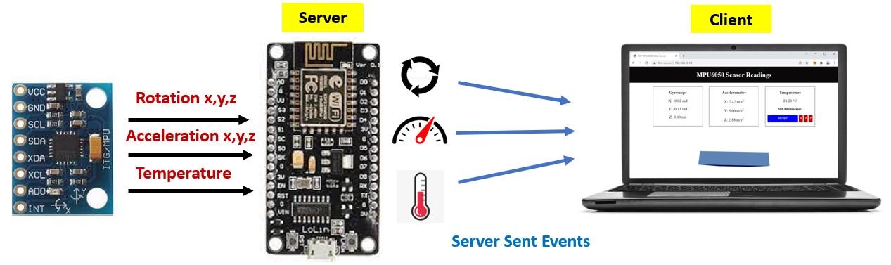
In this tutorial, we will create an ESP8266 MPU6050 sensor readings Web Server dashboard. The readings will consist of the current temperature in degree Celsius, rotational position (x,y,z) and acceleration (x, y, z) using server sent events (SSE). The web server will display sensor readings received by an ESP8266 board connected with an MPU6050 sensor. Additionally, a 3-D animation of the sensor orientation will also be displayed on the web server which we will create using the three.js library. MPU6050 module is used to measure acceleration, temperature, displacement, and angular velocity. It is equipped with 6-axis motion tracking sensors which are integrated inside MPU6050 the chip. Data transmission occurs over the I2C protocol.
Moreover, using SSE we will build our web server that will automatically update sensor readings acquired from the MPU6050 sensor to all connected web clients. Our client will receive automatic updates from the ESP8266 board with SSE through an HTTP connection. This will be highly useful to automatically send new sensor readings to the web client whenever they will be available. Without making any additional requests, the webpage will spontaneously update.
Additionally, to make our ESP8266 web server project more convenient and practical we will use the feature of ESP8266 LittleFS. We will save the HTML, CSS, and JavaScript files on the ESP8266 LittleFS that will be used to build the web server. We can use LittleFS to store files in the ESP8266’s filesystem without having to use any external memory with our ESP module.
We have a similar guide with ESP32:
Project Overview ESP8266 MPU6050 Sensor Readings Dashboard
We aim to build a webpage that will display sensor readings obtained from MPU6050 connected with the ESP8266 module using server sent events. The ESP8266 board will be programmed using Arduino IDE.
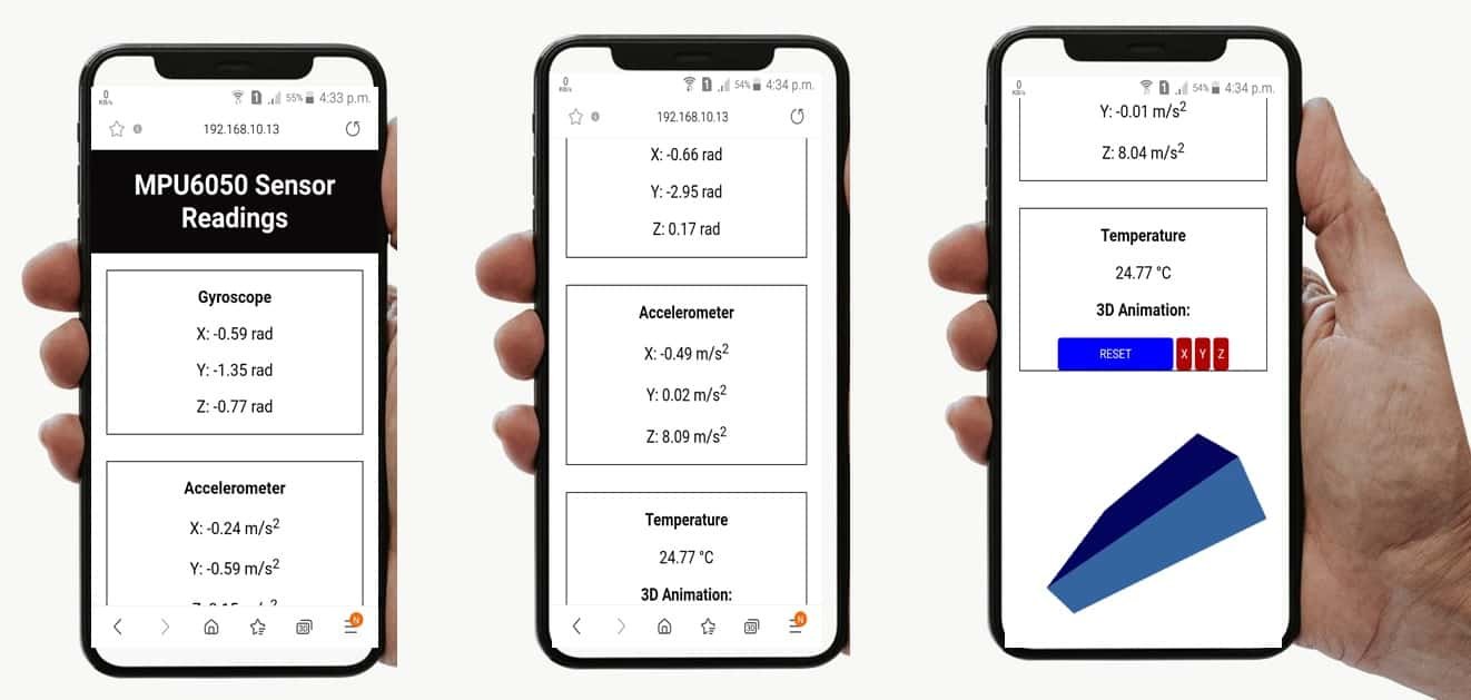
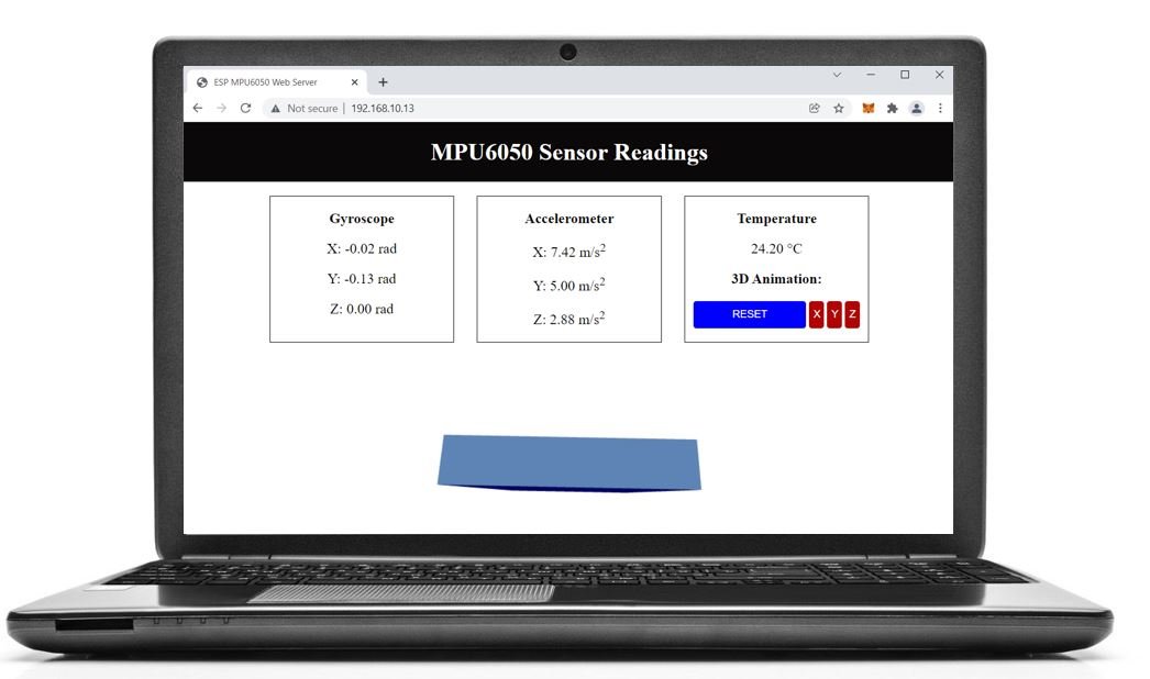
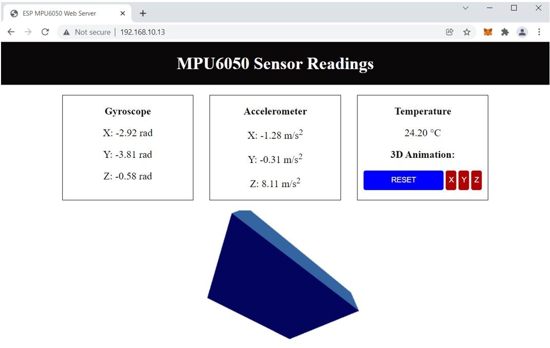
The web server will consist of a heading, “MPU6050 Sensor Readings,” and three boxes each for rotational position, acceleration and temperature readings. The first box will display the gyroscope readings in rad of all three axis x, y and z. Likewise, the second box will display the acceleration readings in m/s^2 in all three axis x, y and z. Thirdly, the last box will display the current temperature readings in degree Celsius. Additionally, we also have a 3-D representation of the sensor orientation displayed beneath the boxes. The third box has a reset feature where clicking the reset button causes the 3-D animation to go back to its initial position. Moreover, we can also reset individual x, y and z positions as well by clicking on their respective buttons.
Working Process
The ESP8266 server will receive the sensor readings via the I2C protocol. Additionally, the transmission of these sensor readings from the server (ESP8266 receiver) to the client (web page) will occur through Server-Sent Events. The gyroscope readings will automatically update after every 10 milliseconds, the accelerometer readings will update after every 200 milliseconds and the temperature readings will update after every 1 second to new values when the web page receives them. Through SSE protocol, it will be very easy to update the sensor readings on our web page without adding any additional requests.
Additionally, the web page will display a 3-D representation of the MPU6050 module’s orientation. This will be created using a JavaScript library called three.js and will use the gyroscope readings to monitor the position of the module. The reset button also gives the feature to set the angular position on all axis back to zero.
You can learn more about ESP8266 web server created through server sent events (SSE) here:
MPU-6050 Module Introduction
MPU6050 module consists of a digital motion that performs all complex processing, computations and provides sensor data output to other MCUs over I2C communication. It is widely used in measuring the health and operating parameters of various machines. It is also used in applications of robotics and motion sensors. This sensor is based upon MEMS (Micro-Mechanical Systems) technology hence it is extremely compact and accurate in certain frequencies. It has a relatively small size and low power consumption. It communicates with other microcontrollers and sensors via I2C communication.
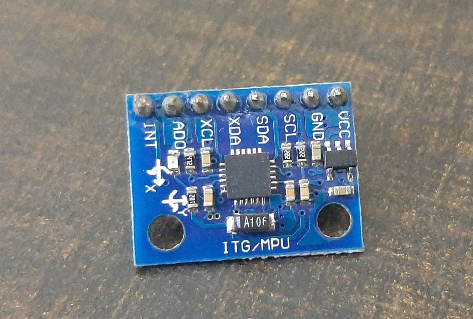
The module consists of 3-axis accelerometers, a 3-axis gyroscope and a built-in temperature sensor. All of these are present on a single chip. The module takes into account the x, y and z channels at the same time because it has 16 bits analog converter dedicated for each channel.
The 3-axis accelerometer measures the rate of change of velocity (m/s^2) or the acceleration of the object. This measurement can be performed on both stationary and moving objects. For stationary objects the rate of change of velocity is equal to the gravitational acceleration (9.8 m/s^2) or gravity in short.The module also has a 3-axis gyroscope which measures the rotational velocity of an object in rad/s. This feature helps us understand the exact orientation of the object.
Features
Some of the key features of MPU6050 Module include:
- Built-in I2C sensor bus which is used to provide gyroscope, accelerometer, and temperature sensor data to other devices such as microcontrollers.
- Onboard pull-up resistor so we do not need to connect external pull resistors which are a requirement for the I2C bus interface.
- User Programmable gyroscope and accelerometer with the help of 16-bit analog to digital converter.
- 1024 Byte FIFO buffer to provide data to the connected microcontroller in high speed and enters the low power mode afterwards.
- Built-in temperature sensor.
MPU-6050 Pinout
Let’s look at the pinout of the MPU6050 Module below.
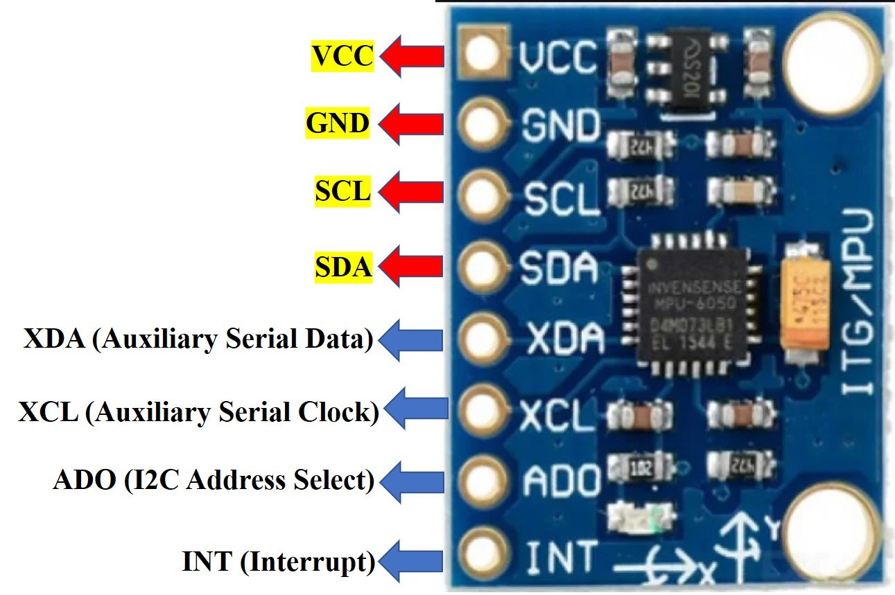
The table below shows a brief description for each pin.
| Pin Name | Description |
| VCC | This will power up the sensor. It can be in range 3.3-5V. |
| GND | This is the ground pin connected with the common ground. |
| SCL | This is the serial clock pin which is used in connecting with the microcontroller through its I2C pin. |
| SDA | This is the serial data pin which connects with the microcontroller’s I2C pin. |
| XDA | This is the auxiliary serial data pin which is used to connect other I2C sensors with the module. |
| XCL | This is the auxiliary serial clock pin which is used to connect other I2C sensors with the module. |
| ADO | This is the I2C address select pin. It is used in changing the I2C address. |
| INT | This is the interrupt pin. It could be used in distinguishing when a new measurement data is available. |
MPU-6050 Interfacing with ESP8266
We will be requiring the following components in this project.
- ESP8266 NodeMCU development board
- MPU6050 Module
- Breadboard
- Connecting Wires
As you see, the MPU6050 has 8 terminals but in order to connect with ESP8266, we will only require the first four pins highlighted in yellow. These are VCC, GND, SCL, and SDA. The table shows the connections between the two modules.
| MPU6050 Module | ESP8266 Module |
| VCC | 3.3V |
| GND | GND (common ground) |
| SCL | D1 GPIO5 (I2C SCL) |
| SDA | D2 GPIO4 (I2C SDA) |
The VCC pin is connected with the 3.3V from the ESP8266 module to power up. Both the grounds of the two devices are connected in common. The SCL pin of MPU6050 is connected with the default SCL pin of ESP8266 NodeMCU. Likewise, the SDA pin is connected with the default SDA pin of ESP8266 NodeMCU.
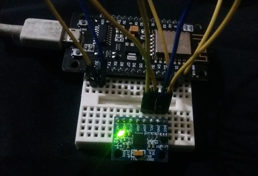
Assemble the two modules as shown below:
Recommended Reading: MPU-6050 with ESP8266 NodeMCU Accelerometer, Gyroscope, and Temperature Sensor (Arduino IDE)
Setting up Arduino IDE for ESP8266 MPU6050 Web Server
We will use Arduino IDE to program our ESP8266 development board. Thus, you should have the latest version of Arduino IDE. Additionally, you also need to install the ESP8266 plugin. You can visit the link shown below to have a look.
Also, you will have to download and install the ESP8266 Filesystem Uploader Plugin in your Arduino IDE so that you are able to upload the LittleFS files on your ESP8266 board. If you haven’t, you can follow this tutorial:
Installing Libraries
We will need the following libraries to build our ESP8266 MPU6050 web server.
- ESPAsyncWebServer library
- ESPAsyncTCP library
- MPU6050 libraries (Adafruit MPU6050, Adafruit Unified Sensor and Adafruit Bus IO library)
- Arduino_JSON library
The ESPAsyncWebServer library will help us in creating our web server easily. With this library, we will set up an asynchronous web server. ESPAsyncTCP library will also be incorporated as it a dependency for the ESPAsyncWebServer library. These two libraries are not available in the Arduino library manager. Therefore, we will have to download and load them on our ESP8266 board ourselves.
- To install the ESPAsyncWebServer library for free, click here to download. You will download the library as a .zip folder which you will extract and rename as ‘ESPAsyncWebServer.’ Then, transfer this folder to the installation library folder in your Arduino IDE.
- To install the ESPAsync TCP library for free, click here to download. You will download the library as a .zip folder which you will extract and rename as ‘ESPAsyncTCP.’ Then, transfer this folder to the installation library folder in your Arduino IDE.
Likewise, you can also go to Sketch > Include Library > Add .zip Library inside the IDE to add the libraries as well.
Installing MPU6050 Libraries
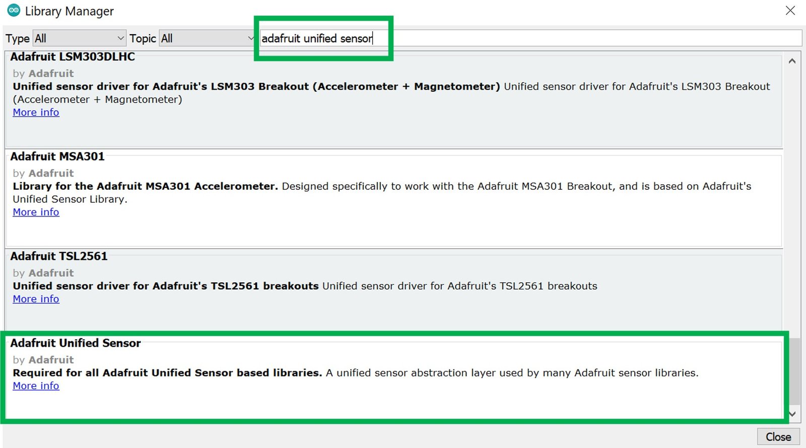
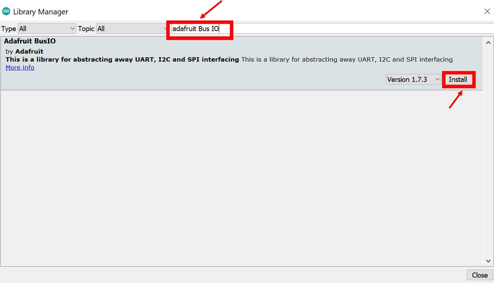
To ensure the proper functionality of our project, we will first install the MPU6050 library in our IDE. There are many options for the MPU-6050 library for Arduino IDE. But we will use the Adafruit MPU6050 library. To use this library, two more libraries have to be installed as well, namely the Adafruit Unified Sensor library and the Adafruit Bus IO Library.
Go to Sketch > Include Library > Manage Libraries and type ‘Adafruit mpu6050’ in the search bar. Install the latest version of the library.

Now search for ‘Adafruit unified sensor.’ You will see several different libraries from this search. Go to the bottom of the search options and look for the following library highlighted in the green rectangle and install it.
Now we have to install the last library to ensure the proper functionality of the project. Type ‘Adafruit Bus IO’ and install it as well.
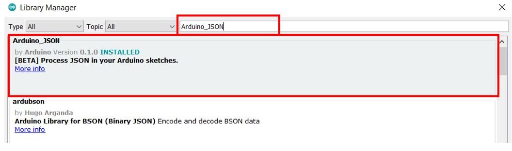
Installing Arduino_JSON Library
You will also have to install the Arduino_JSON library as we will be dealing with JSON script. Open your Arduino Library Manager by clicking Sketch > Include Library > Manage Libraries. Type ‘Arduino_JSON’ in the search tab and press enter. Install the library which is highlighted below.
After installation of the libraries, restart your IDE.
Creating Files for LittleFS
In most of our web server projects with ESP8266, we have included HTML and CSS files inside our Arduino sketch. We save these HTML documents inside Arduino sketch by converting them into strings. Whenever a web client makes an HTTTP request, we send this string as a response which is basically a web page. On the contrary, with LittleFS, we can save HTML, CSS, and JavaScript files in ESP8266 flash file system. Whenever a web client makes a request, we can serve these files directly from LittleFS. It is convenient to have separate HTML, CSS, and JavaScript files saved on the ESP8266 LittleFS. All of these three files will later be linked together.
To build an ESP8266 web server using LittleFS, we will create four different files: HTML, CSS, JavaScript and Arduino sketch and organize them in a project folder like shown below:
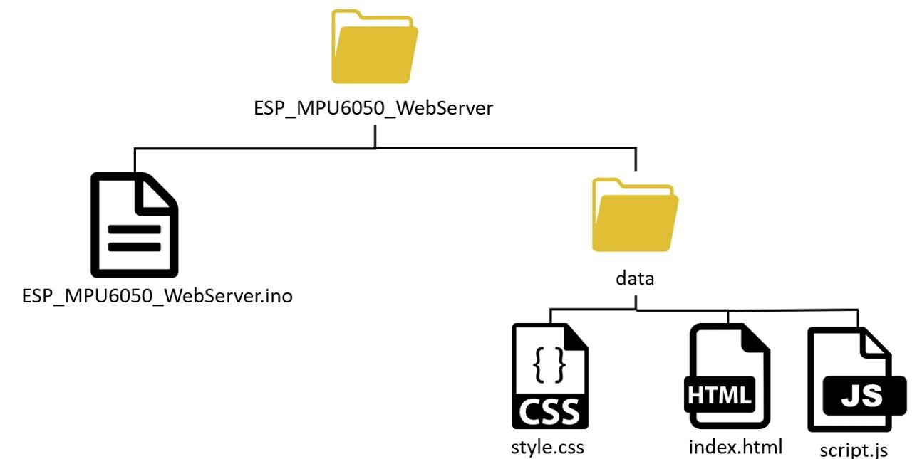
Note: You should place HTML, CSS and JavaScript files inside the data folder. Otherwise, LittleFS library will not be able to read these files.
You can read our previous LittleFS web server tutorial with ESP8266:
Creating HTML file
Inside our HTML file, we will specify the title of the web page, the three boxes, and the 3-D representation of our MPU6050 module., motor state, and the arrow icon. Each box will display sensor readings consisting of angular position in rad, acceleration in m/s^2, and temperature in degrees Celsius.
Now, create an index.html file and replicate the code given below in that file.
<!DOCTYPE HTML><html>
<head>
<title>ESP MPU6050 Web Server</title>
<meta name="viewport" content="width=device-width, initial-scale=1">
<link rel="icon" href="data:,">
<link rel="stylesheet" type="text/css" href="style.css">
https://cdnjs.cloudflare.com/ajax/libs/three.js/107/three.min.js
</head>
<body>
<div class="topnav">
<h1> MPU6050 Sensor Readings</h1>
</div>
<div class="content">
<div class="cards">
      <div class="card">
        <p class="card-title">Gyroscope</p>
        <p><span class="reading">X: <span id="rotationX"></span> rad</span></p>
        <p><span class="reading">Y: <span id="rotationY"></span> rad</span></p>
        <p><span class="reading">Z: <span id="rotationZ"></span> rad</span></p>
      </div>
      <div class="card">
        <p class="card-title">Accelerometer</p>
        <p><span class="reading">X: <span id="accelerationX"></span> m/s<sup>2</sup></span></p>
        <p><span class="reading">Y: <span id="accelerationY"></span> m/s<sup>2</sup></span></p>
        <p><span class="reading">Z: <span id="accelerationZ"></span> m/s<sup>2</sup></span></p>
      </div>
<div class="card">
<p class="card-title">Temperature</p>
<p><span class="reading"><span id="temperature"></span> °C</span></p>
<p class="card-title">3D Animation:</p>
        <button id="reset" onclick="resetPosition(this)">RESET</button>
        <button id="resetX" onclick="resetPosition(this)">X</button>
        <button id="resetY" onclick="resetPosition(this)">Y</button>
        <button id="resetZ" onclick="resetPosition(this)">Z</button>
</div>
</div>
<div class="cube-content">
      <div id="3Dcube"></div>
    </div>
  </div>
http://script.js
</body>
</html>Building the Web page
We will start with the title of the web page. The tag will indicate the beginning of the title and the </tile> tag will indicate the ending. In between these tags, we will specify “ESP MPU6050 Web Server” which will be displayed in the browser’s title bar </p>.
<title>ESP MPU6050 Web Server</title>Next, we will create a meta tag to make sure our web server is available for all browsers e.g., smartphones, laptops, computers etc.
<meta name="viewport" content="width=device-width, initial-scale=1">Between the <head></head> tags, we will reference the CSS file as we’ll be creating different files for both HTML and CSS by using the <link> tag. This tag will be used so that we can link with an external style sheet which we will specify as a CSS file. It will consist of three attributes. The first one is rel which shows the relationship between the current file and the one which is being linked.
We will specify “stylesheet” which will change the visuals of the web page. The second attribute is type which we will specify as “text/css” as we will be using the CSS file for styling purpose. The third attribute is href and it will specify the location of the linked file. Both of the files (HTML & CSS) will be saved in the same folder (data) so we will just specify the name of the CSS file that is “style.css.”
rel="stylesheet" type="text/css" href="style.css">Additionally, we will reference the three.js library as well to create the 3-D representation of the sensor.
https://cdnjs.cloudflare.com/ajax/libs/three.js/107/three.min.jsBody
Inside the HTML web page body, we will include the heading, the boxes and the 3-D object. This will go inside the <body></body> tags which will mark the beginning and the ending of the script.
We will include the heading of our webpage inside the <h1></h1> tags and it will be “MPU6050 Sensor Readings”.
<h1> MPU6050 Sensor Readings</h1>Next, the following lines of code will display texts and boxes for the three sensor readings acquired from the MPU6050 module and the reset buttons. We will specify the name, icon and colour for each box.
Also, JavaScript will be in charge of handling the received data so that the readings will be updated correctly. This will be accomplished by using the unique ids which we referenced in our script. Thus, whenever the client will receive a new event with the updated readings, the HTML elements with their respective ids will get updated to newer values.
<div class="content">
<div class="cards">
<div class="card">
<p class="card-title">Gyroscope</p>
<p><span class="reading">X: <span id="rotationX"></span> rad</span></p>
<p><span class="reading">Y: <span id="rotationY"></span> rad</span></p>
<p><span class="reading">Z: <span id="rotationZ"></span> rad</span></p>
</div>
<div class="card">
<p class="card-title">Accelerometer</p>
<p><span class="reading">X: <span id="accelerationX"></span> m/s<sup>2</sup></span></p>
<p><span class="reading">Y: <span id="accelerationY"></span> m/s<sup>2</sup></span></p>
<p><span class="reading">Z: <span id="accelerationZ"></span> m/s<sup>2</sup></span></p>
</div>
<div class="card">
<p class="card-title">Temperature</p>
<p><span class="reading"><span id="temperature"></span> °C</span></p>
<p class="card-title">3D Animation:</p>
<button id="reset" onclick="resetPosition(this)">RESET</button>
<button id="resetX" onclick="resetPosition(this)">X</button>
<button id="resetY" onclick="resetPosition(this)">Y</button>
<button id="resetZ" onclick="resetPosition(this)">Z</button>
</div>
</div>Gyroscope Box
The first box will display the gyroscope readings. The title of the card will be ‘Gyroscope.’ We will be displaying the angular position on the x-axis, the y-axis, and the z-axis respectively. Therefore we will create three separate paragraphs to display each reading on the particular axis. All of the sensor readings will be referenced to the class ‘readings’. We will set up unique span ids for each reading value. For the gyroscope readings we have three span ids associated with angular velocity on the x-axis, y-axis and the z-axis. They are ‘rotationX’, rotationY’ and ‘rotationZ’ respectively.
<div class="card">
<p class="card-title">Gyroscope</p>
<p><span class="reading">X: <span id="rotationX"></span> rad</span></p>
<p><span class="reading">Y: <span id="rotationY"></span> rad</span></p>
<p><span class="reading">Z: <span id="rotationZ"></span> rad</span></p>
</div>Accelerometer Box
Likewise, the second box will display the acceleration readings. The title of this card will be ‘Accelerometer.’ We will be displaying the acceleration on the x-axis, the y-axis, and the z-axis respectively. Therefore we will create three separate paragraphs to display each reading on the particular axis. All of the sensor readings will be referenced to the span class ‘readings’. We will set up unique span ids for each reading value. For the acceleration readings, we have three span ids associated with values on the x-axis, y-axis, and z-axis. They are ‘accelerationX’, accelerationY’ and ‘accelerationZ’ respectively.
<div class="card">
<p class="card-title">Accelerometer</p>
<p><span class="reading">X: <span id="accelerationX"></span> m/s<sup>2</sup></span></p>
<p><span class="reading">Y: <span id="accelerationY"></span> m/s<sup>2</sup></span></p>
<p><span class="reading">Z: <span id="accelerationZ"></span> m/s<sup>2</sup></span></p>
</div>Temperature & Reset Buttons Box
The third box will display the temperature readings and the reset buttons for the 3-D object. There will be two titles of this card. The first title will be ‘Temperature’ and the second title will be ‘3D Animation.’
<div class="card">
<p class="card-title">Temperature</p>
<p><span class="reading"><span id="temperature"></span> °C</span></p>
<p class="card-title">3D Animation:</p>
<button id="reset" onclick="resetPosition(this)">RESET</button>
<button id="resetX" onclick="resetPosition(this)">X</button>
<button id="resetY" onclick="resetPosition(this)">Y</button>
<button id="resetZ" onclick="resetPosition(this)">Z</button>
</div>Under the ‘Temperature’ title we will display the temperature reading in degree Celsius. The unique span id for this will be ‘temperature.’
<p class="card-title">Temperature</p>
<p><span class="reading"><span id="temperature"></span> °C</span></p>Under the ‘3D Animation’ title we will display four reset buttons. Each button is associated with a different button id and a JavaScript function called resetPosition(). The first button denoted by ‘RESET’ resets the position of the 3-D object on all the axis. The second button denoted by ‘X’ resets the x-axis position. The third button denoted by ‘Y’ resets the y-axis position. The fourth button denoted by ‘Z’ resets the z-axis position.
<p class="card-title">3D Animation:</p>
<button id="reset" onclick="resetPosition(this)">RESET</button>
<button id="resetX" onclick="resetPosition(this)">X</button>
<button id="resetY" onclick="resetPosition(this)">Y</button>
<button id="resetZ" onclick="resetPosition(this)">Z</button>The 3-D representation of the module has the id ‘3Dcube’ and is part of the ‘cube-content’ class.
<div class="cube-content">
<div id="3Dcube"></div>
</div>
</div>Creating CSS File
Next, create another file “style.css” in the data folder and copy the code given below in that file. CSS is used to give styles to a web page.
html {
  font-family: New Times Roman;
  display: inline-block;
  text-align: center;
}
p {
  font-size: 1.2rem;
}
body {
  margin: 0;
}
.topnav {
  overflow: hidden;
  background-color: #0a0808;
  color: #ffffff;
  font-size: 1rem;
}
.content {
  padding: 20px;
}
.card {
  background-color: white;
  outline: 1px solid;
}
.card-title {
  color:#0a0808;
  font-weight: bold;
}
.cards {
  max-width: 800px;
  margin: 0 auto;
  display: grid; grid-gap: 2rem;
  grid-template-columns: repeat(auto-fit, minmax(200px, 1fr));
}
.reading {
  font-size: 1.2rem;
}
.cube-content{
  width: 100%;
  background-color: white;
  height: 300px; margin: auto;
  padding-top:2%;
}
#reset{
  border: none;
  color: #ffffff;
  background-color: #0000FF;
  padding: 10px;
  text-align: center;
  display: inline-block;
  font-size: 14px; width: 150px;
  border-radius: 4px;
}
#resetX, #resetY, #resetZ{
  border: none;
  color: #ffffff;
  background-color: #b00404;
  padding-top: 10px;
  padding-bottom: 10px;
  text-align: center;
  display: inline-block;
  font-size: 14px;
  width: 20px;
  border-radius: 4px;
}
To add CSS files in head tags, we will use <style></style> tags to mark the beginning and the end. We will set the display text to font type Times New Roman and align it in the centre of the webpage. The font size, colour and positioning of the heading, paragraphs, the cards and the buttons will also be set.
Creating JavaScript File
Now create another file in the data folder and name it ‘script.js.’ The JavaScript file will be responsible for handling the SSE events and the 3-D object manipulation.
let scene, camera, rendered, cube;

function parentWidth(elem) {
  return elem.parentElement.clientWidth;
}

function parentHeight(elem) {
  return elem.parentElement.clientHeight;
}

function initialize_3D(){
  scene = new THREE.Scene();
  scene.background = new THREE.Color(0xffffff);

  camera = new THREE.PerspectiveCamera(75, parentWidth(document.getElementById("3Dcube")) / parentHeight(document.getElementById("3Dcube")), 0.1, 1000);

  renderer = new THREE.WebGLRenderer({ antialias: true });
  renderer.setSize(parentWidth(document.getElementById("3Dcube")), parentHeight(document.getElementById("3Dcube")));

  document.getElementById('3Dcube').appendChild(renderer.domElement);

  const geometry = new THREE.BoxGeometry(5, 1, 4);

var cubeMaterials = [
  new THREE.MeshBasicMaterial({color:0x03045e}),
  new THREE.MeshBasicMaterial({color:0x5d84b4}),
  new THREE.MeshBasicMaterial({color:0x3565a1}),
  new THREE.MeshBasicMaterial({color:0x03045e}),
  new THREE.MeshBasicMaterial({color:0x5d84b4}),
  new THREE.MeshBasicMaterial({color:0x3565a1}),
];

  const material = new THREE.MeshFaceMaterial(cubeMaterials);

  cube = new THREE.Mesh(geometry, material);
  scene.add(cube);
  camera.position.z = 5;
  renderer.render(scene, camera);
}

function onWindowResize(){
  camera.aspect = parentWidth(document.getElementById("3Dcube")) / parentHeight(document.getElementById("3Dcube"));
  //camera.aspect = window.innerWidth /  window.innerHeight;
  camera.updateProjectionMatrix();
  //renderer.setSize(window.innerWidth, window.innerHeight);
  renderer.setSize(parentWidth(document.getElementById("3Dcube")), parentHeight(document.getElementById("3Dcube")));

}

window.addEventListener('resize', onWindowResize, false);

initialize_3D();

if (!!window.EventSource) {
  var source = new EventSource('/events');

  source.addEventListener('open', function(e) {
    console.log("Events Connected");
  }, false);

  source.addEventListener('error', function(e) {
    if (e.target.readyState != EventSource.OPEN) {
      console.log("Events Disconnected");
    }
  }, false);

  source.addEventListener('gyro_readings', function(e) {
    var obj = JSON.parse(e.data);
    document.getElementById("rotationX").innerHTML = obj.rotationX;
    document.getElementById("rotationY").innerHTML = obj.rotationY;
    document.getElementById("rotationZ").innerHTML = obj.rotationZ;

    cube.rotation.x = obj.rotationY;
    cube.rotation.z = obj.rotationX;
    cube.rotation.y = obj.rotationZ;
    renderer.render(scene, camera);
  }, false);

  source.addEventListener('temperature_reading', function(e) {
    console.log("temperature_reading", e.data);
    document.getElementById("temperature").innerHTML = e.data;
  }, false);

  source.addEventListener('accelerometer_readings', function(e) {
    console.log("accelerometer_readings", e.data);
    var obj = JSON.parse(e.data);
    document.getElementById("accelerationX").innerHTML = obj.accelerationX;
    document.getElementById("accelerationY").innerHTML = obj.accelerationY;
    document.getElementById("accelerationZ").innerHTML = obj.accelerationZ;
  }, false);
}

function resetPosition(element){
  var xhr = new XMLHttpRequest();
  xhr.open("GET", "/"+element.id, true);
  console.log(element.id);
  xhr.send();
}
Handling 3-D Object
The following lines of code are responsible for creating the 3-D object and its handling process.
let scene, camera, rendered, cube;

function parentWidth(elem) {
  return elem.parentElement.clientWidth;
}

function parentHeight(elem) {
  return elem.parentElement.clientHeight;
}

function initialize_3D(){
  scene = new THREE.Scene();
  scene.background = new THREE.Color(0xffffff);

  camera = new THREE.PerspectiveCamera(75, parentWidth(document.getElementById("3Dcube")) / parentHeight(document.getElementById("3Dcube")), 0.1, 1000);

  renderer = new THREE.WebGLRenderer({ antialias: true });
  renderer.setSize(parentWidth(document.getElementById("3Dcube")), parentHeight(document.getElementById("3Dcube")));

  document.getElementById('3Dcube').appendChild(renderer.domElement);

  const geometry = new THREE.BoxGeometry(5, 1, 4);

var cubeMaterials = [
  new THREE.MeshBasicMaterial({color:0x03045e}),
  new THREE.MeshBasicMaterial({color:0x5d84b4}),
  new THREE.MeshBasicMaterial({color:0x3565a1}),
  new THREE.MeshBasicMaterial({color:0x03045e}),
  new THREE.MeshBasicMaterial({color:0x5d84b4}),
  new THREE.MeshBasicMaterial({color:0x3565a1}),
];

  const material = new THREE.MeshFaceMaterial(cubeMaterials);

  cube = new THREE.Mesh(geometry, material);
  scene.add(cube);
  camera.position.z = 5;
  renderer.render(scene, camera);
}

function onWindowResize(){
  camera.aspect = parentWidth(document.getElementById("3Dcube")) / parentHeight(document.getElementById("3Dcube"));
  //camera.aspect = window.innerWidth /  window.innerHeight;
  camera.updateProjectionMatrix();
  //renderer.setSize(window.innerWidth, window.innerHeight);
  renderer.setSize(parentWidth(document.getElementById("3Dcube")), parentHeight(document.getElementById("3Dcube")));

}

window.addEventListener('resize', onWindowResize, false);

initialize_3D();
We will define a function called init3D() that will we used to build the object. This will be done using the three.js JavaScript library. To do that we will first define scene, camera and renderer as follows:
let scene, camera, rendered, cube;We will use BoxGeometry() specify the dimensions of the 3D object to create it.
const geometry = new THREE.BoxGeometry(5, 1, 4);And then create a mesh basic material and set its colour. We have set three different colours to differentiate the different sides of the object.
var cubeMaterials = [
  new THREE.MeshBasicMaterial({color:0x03045e}),
  new THREE.MeshBasicMaterial({color:0x5d84b4}),
  new THREE.MeshBasicMaterial({color:0x3565a1}),
  new THREE.MeshBasicMaterial({color:0x03045e}),
  new THREE.MeshBasicMaterial({color:0x5d84b4}),
  new THREE.MeshBasicMaterial({color:0x3565a1}),
];
Finally, create the 3D object, add it to the scene and adjust the camera.
cube = new THREE.Mesh(geometry, material);
scene.add(cube);
camera.position.z = 5;
renderer.render(scene, camera);
The onWindowResize() function will be responsible to change the size of the object according to the web browser window size. This function will respond to the event ‘resize.’
function onWindowResize(){
  camera.aspect = parentWidth(document.getElementById("3Dcube")) / parentHeight(document.getElementById("3Dcube"));
  //camera.aspect = window.innerWidth /  window.innerHeight;
  camera.updateProjectionMatrix();
  //renderer.setSize(window.innerWidth, window.innerHeight);
  renderer.setSize(parentWidth(document.getElementById("3Dcube")), parentHeight(document.getElementById("3Dcube")));
}

window.addEventListener('resize', onWindowResize, false);
Calling the init3D() function will create the 3D object.
init3D();Receiving and handling SSE events
Now we will start the EventSource connection with the server and handle the events which will be received from the server.
Firstly, we will define an event source and pass the /events URL inside it. This URL will send the updates to our web page.
if (!!window.EventSource) {
 var source = new EventSource('/events');
Then, we will use the addEventListener() function to listen to incoming events. It will have two arguments. The first will be the event name and the second will be function(e).
The following are listeners for connection, disconnection and incoming messages from the server. We used the default event listeners in this case which were listed in the Documentation.
 source.addEventListener('open', function(e) {
  console.log("Events Connected");
 }, false);
 source.addEventListener('error', function(e) {
  if (e.target.readyState != EventSource.OPEN) {
    console.log("Events Disconnected");
  }
 }, false);
Event Listeners for Sensor Readings
Next, we will include listener for the event ‘gyro_readings.’ After every 10 milliseconds the ESP8266 will receive new sensor readings from the sensor. The ‘gyro_readings’ event will be sent to the web server. When the client will receive the particular event, it will print the data on the browser console. Additionally, the new readings will also get saved to their elements with their respective ids. The 3-D object’s position will also be changed accordingly. Notice that we have created a variable of type ‘var’ named ‘obj’. This will save the sensor reading data which was initially in the form of a JSON string to a JavaScript object. Thus, we will access each reading via the ‘obj’ variable.
source.addEventListener('gyro_readings', function(e) {
    var obj = JSON.parse(e.data);
    document.getElementById("rotationX").innerHTML = obj.rotationX;
    document.getElementById("rotationY").innerHTML = obj.rotationY;
    document.getElementById("rotationZ").innerHTML = obj.rotationZ;

    cube.rotation.x = obj.rotationY;
    cube.rotation.z = obj.rotationX;
    cube.rotation.y = obj.rotationZ;
    renderer.render(scene, camera);
  }, false);
Likewise, we will include listener for the event ‘temperature_reading.’ After every second the ESP8266 will receive a new temperature reading from the sensor. The ‘temperature_reading’ event will be sent to the web server. When the client will receive the particular event, it will print the data on the browser console. Additionally, the new reading will also get saved to its element with its respective id.
  source.addEventListener('temperature_reading', function(e) {
    console.log("temperature_reading", e.data);
    document.getElementById("temperature").innerHTML = e.data;
  }, false);
Next, we will include listener for the event ‘accelerometer_readings.’ After every 200 milliseconds the ESP8266 will receive new acceleration readings from the sensor. The ‘accelerometer_readings’ event will be sent to the web server. When the client will receive the particular event, it will print the data on the browser console. Additionally, the new readings will also get saved to their elements with their respective ids. Notice that we have created a variable of type ‘var’ named ‘obj’. This will save the sensor reading data which was initially in the form of a JSON string to a JavaScript object. Thus, we will access each reading via the ‘obj’ variable.
  source.addEventListener('accelerometer_readings', function(e) {
    console.log("accelerometer_readings", e.data);
    var obj = JSON.parse(e.data);
    document.getElementById("accelerationX").innerHTML = obj.accelerationX;
    document.getElementById("accelerationY").innerHTML = obj.accelerationY;
    document.getElementById("accelerationZ").innerHTML = obj.accelerationZ;
  }, false);
resetPosition()
function resetPosition(element){
  var xhr = new XMLHttpRequest();
  xhr.open("GET", "/"+element.id, true);
  console.log(element.id);
  xhr.send();
}
The resetPosition() is called whenever the user clicks the reset buttons present on the web page.
Through this function, the HTTP GET request will be made to the ESP8266 module regarding resetting the position of the 3-D object. It will create the HTTP GET request whenever any of the reset button will be clicked. This will be done by redirecting it on the URL (“/”+element.id) of the particular button that was clicked. Remember each button was associated with a different id.
Inside this function we use the XMLHttpRequest. This will allow us to make an HTTP request in JavaScript. To make the HTTP GET request to we will follow three steps:
Firstly, we will create an XMLHttpRequest as follows:
var xhr = new XMLHttpRequest();Secondly, we will initialize the request by using the xhr.open() method. Inside it we will pass on three arguments. The first argument specifies the type of HTTP method which is GET in our case. The second argument is the URL to which are ESP8266 will request upon. It will be a different URL for each button. The last argument is true which specifies that the request is asynchronous.
xhr.open("GET", "/"+element.id, true);Lastly, we will use xhr.send() to open the connection. Our server (ESP8266) will now be able to receive the HTTP GET request whenever the user will interact with the button.
xhr.send();Arduino Sketch ESP8266 MPU-6050 Web Server
Now, open your Arduino IDE and go to File > New to open a new file. Copy the code given below in that file and save it as ‘ESP_MP6050_WebServer’.
#include <Arduino.h>
#include <ESP8266WiFi.h>
#include <ESPAsyncTCP.h>
#include <ESPAsyncWebServer.h>
#include <Adafruit_MPU6050.h>
#include <Adafruit_Sensor.h>
#include <Arduino_JSON.h>
#include <LittleFS.h>

const char* ssid = "Your_SSID";
const char* password = "Your_Password";

AsyncWebServer server(80);
AsyncEventSource events("/events");

JSONVar readings;
unsigned long previous_time = 0;
unsigned long previous_time_temp = 0;
unsigned long previous_time_acceleration = 0;
unsigned long gyro_delay  = 10;
unsigned long temperature_delay  = 1000;
unsigned long accelerometer_delay  = 200;

Adafruit_MPU6050 mpu;
sensors_event_t a, g, temp;

float rotationX, rotationY, rotationZ;
float accelerationX, accelerationY, accelerationZ;
float temperature;

float rotationX_error = 0.05;
float rotationY_error = 0.02;
float rotationZ_error = 0.01;

String getGyroscopeReadings(){
  mpu.getEvent(&a, &g, &temp);

  float rotationX_temporary = g.gyro.x;
  if(abs(rotationX_temporary) > rotationX_error)  {
    rotationX += rotationX_temporary*0.01;
  }

  float rotationY_temporary = g.gyro.y;
  if(abs(rotationY_temporary) > rotationY_error) {
    rotationY += rotationY_temporary*0.01;
  }

  float rotationZ_temporary = g.gyro.z;
  if(abs(rotationZ_temporary) > rotationZ_error) {
    rotationZ += rotationZ_temporary*0.01;
  }

  readings["rotationX"] = String(rotationX);
  readings["rotationY"] = String(rotationY);
  readings["rotationZ"] = String(rotationZ);

  String jsonString = JSON.stringify(readings);
  return jsonString;
}

String getAccelerationReadings() {
  mpu.getEvent(&a, &g, &temp);
  accelerationX = a.acceleration.x;
  accelerationY = a.acceleration.y;
  accelerationZ = a.acceleration.z;
  readings["accelerationX"] = String(accelerationX);
  readings["accelerationY"] = String(accelerationY);
  readings["accelerationZ"] = String(accelerationZ);
  String accString = JSON.stringify (readings);
  return accString;
}

String getTemperatureReadings(){
  mpu.getEvent(&a, &g, &temp);
  temperature = temp.temperature;
  return String(temperature);
}

void setup() {
  Serial.begin(115200);
  WiFi.mode(WIFI_STA);
  WiFi.begin(ssid, password);
  Serial.println("");
  Serial.print("Connecting to WiFi...");
  while (WiFi.status() != WL_CONNECTED) {
    Serial.print(".");
    delay(1000);
  }
  Serial.println("");
  Serial.println(WiFi.localIP());

  // Initialize LittleFS
  if(!LittleFS.begin()){
    Serial.println("An Error has occurred while mounting LittleFS");
    return;
  }

  if (!mpu.begin()) {
    Serial.println("MPU6050 is not properly connected. Check circuit!");
    while (1) {
      delay(10);
    }
  }
  Serial.println("MPU6050 Found");

  server.on("/", HTTP_GET, [](AsyncWebServerRequest *request){
    request->send(LittleFS, "/index.html", "text/html");
  });

  server.serveStatic("/",LittleFS, "/");

  server.on("/reset", HTTP_GET, [](AsyncWebServerRequest *request){
    rotationX=0;
    rotationY=0;
    rotationZ=0;
    request->send(200, "text/plain", "OK");
  });

  server.on("/resetX", HTTP_GET, [](AsyncWebServerRequest *request){
    rotationX=0;
    request->send(200, "text/plain", "OK");
  });

  server.on("/resetY", HTTP_GET, [](AsyncWebServerRequest *request){
    rotationY=0;
    request->send(200, "text/plain", "OK");
  });

  server.on("/resetZ", HTTP_GET, [](AsyncWebServerRequest *request){
    rotationZ=0;
    request->send(200, "text/plain", "OK");
  });

  events.onConnect([](AsyncEventSourceClient *client){
    if(client->lastId()){
      Serial.printf("Client reconnected! Last message ID that it got is: %u\n", client->lastId());
    }
    client->send("hello!", NULL, millis(), 10000);
  });
  server.addHandler(&events);

  server.begin();
}

void loop() {
  if ((millis() - previous_time) > gyro_delay ) {
    events.send(getGyroscopeReadings().c_str(),"gyro_readings",millis());
    previous_time = millis();
  }
  if ((millis() - previous_time_acceleration) > accelerometer_delay ) {
    events.send(getAccelerationReadings().c_str(),"accelerometer_readings",millis());
    previous_time_acceleration = millis();
  }
  if ((millis() - previous_time_temp) > temperature_delay ) {
    events.send(getTemperatureReadings().c_str(),"temperature_reading",millis());
    previous_time_temp = millis();
  }
}
How the Code Works?
Firstly, we will include the necessary libraries. As we have to connect our ESP8266 to a wireless network hence we need ESP8266WiFi.h library for that purpose. The ESPAsyncWebServer.h and ESPAsyncTCP.h libraries are the ones that we recently downloaded and will be required for the building of the asynchronous web server. The Adafruit_MPU6050 library is used in implementing the hardware functionalities of the sensor whereas the Adafruit_Sensor is a unified sensor library. Additionally, the Arduino_JSON library will be used as we will use a JSON strings to store the angular velocity and the acceleration readings. Also, the LittleFS library will allow us to access the flash memory file system of our ESP8266 core.
#include <Arduino.h>
#include <ESP8266WiFi.h>
#include <ESPAsyncTCP.h>
#include <ESPAsyncWebServer.h>
#include <Adafruit_MPU6050.h>
#include <Adafruit_Sensor.h>
#include <Arduino_JSON.h>
#include <LittleFS.h>
Next, we will create two global variables, one for the SSID and another for the password. These will hold our network credentials which will be used to connect to our wireless router. Replace both of them with your credentials to ensure a successful connection.
const char* ssid = "Your_SSID";
const char* password = "Your_Password";
Creating an AsyncWebServer Object
The AsyncWebServer object will be used to set up the ESP8266 web server. We will pass the default HTTP port which is 80, as the input to the constructor. This will be the port where the server will listen to the requests.
AsyncWebServer server(80);Defining an EventSource
Next, we will define an event source called ‘/events.’ You can use any appropriate name.
AsyncEventSource events("/events");Defining Variables
We will create a JSON variable called ‘readings’ to store the sensor readings.
JSONVar readings;The following variables will be used later on in the code to monitor the time delays after which each sensor reading will be available to our ESP8266 board. We have specified the time delays in milliseconds.
unsigned long previous_time = 0;
unsigned long previous_time_temp = 0;
unsigned long previous_time_acceleration = 0;
unsigned long gyro_delay  = 10;
unsigned long temperature_delay  = 1000;
unsigned long accelerometer_delay  = 200;
Then, we will create an object named ‘mpu’ of Adafruit_MPU6050 to access the different functions of the sensor. Next we will create an object in memory named ‘sensors_event_t’ which will save our sensor readings for the accelerometer (a), gyroscope (g), and temperature (t).
Adafruit_MPU6050 mpu;
sensors_event_t a, g, temp;
The following variables of data type float will also be used later on in the code to access and store the individual angular position on all three axes, acceleration on all three axis and temperature values.
float rotationX, rotationY, rotationZ;
float accelerationX, accelerationY, accelerationZ;
float temperature;
Next, we will specify the error in gyroscope readings for x, y and z axis respectively. These values were obtained after doing a sample test using the MPU6050 module and placing it in a stationary position. You can use the Adafruit MPU6050 library examples ‘basic_readings’ to easily obtain the error values.
float rotationX_error = 0.05;
float rotationY_error = 0.02;
float rotationZ_error = 0.01;
getGyroscopeReadings()
The following getGyroscopeReadings() function will return a JSON string consisting of the angular position of the sensor on the x, y and z-axis.
String getGyroscopeReadings(){
  mpu.getEvent(&a, &g, &temp);

  float rotationX_temporary = g.gyro.x;
  if(abs(rotationX_temporary) > rotationX_error)  {
    rotationX += rotationX_temporary*0.01;
  }

  float rotationY_temporary = g.gyro.y;
  if(abs(rotationY_temporary) > rotationY_error) {
    rotationY += rotationY_temporary*0.01;
  }

  float rotationZ_temporary = g.gyro.z;
  if(abs(rotationZ_temporary) > rotationZ_error) {
    rotationZ += rotationZ_temporary*0.01;
  }

  readings["rotationX"] = String(rotationX);
  readings["rotationY"] = String(rotationY);
  readings["rotationZ"] = String(rotationZ);

  String jsonString = JSON.stringify(readings);
  return jsonString;
}
We will obtain new sensor events with current readings by using the mpu object on the getEvent() function. We will call the getEvent() function which will get readings from the sensor and convert them into an appropriate International System of Units (SI).
mpu.getEvent(&a, &g, &temp);Th sensor readings from the gyroscope depict the angular velocity in rad/s. These will be accessed through g.gyro.x, g.gyro.y and g.gyro.z respectively. Now we will create additional three temporary floating variables for angular velocity reading for all the three axis and save the reading acquired from the sensor in them. Then by using an if statement we will check if the value obtained is valid and then convert it into angular position by multiplying it by the gyro_delay in seconds (100 milliseconds=0.01 seconds). Thus, ‘rotationX’ will give us the position in x-axis, ‘rotationY’ will give us the position in y-axis and ‘rotationZ’ will give us the position in z-axis.
  float rotationX_temporary = g.gyro.x;
  if(abs(rotationX_temporary) > rotationX_error)  {
    rotationX += rotationX_temporary*0.01;
  }

  float rotationY_temporary = g.gyro.y;
  if(abs(rotationY_temporary) > rotationY_error) {
    rotationY += rotationY_temporary*0.01;
  }

  float rotationZ_temporary = g.gyro.z;
  if(abs(rotationZ_temporary) > rotationZ_error) {
    rotationZ += rotationZ_temporary*0.01;
  }
The JSON variable we created previously called ‘readings’ will contain the individual angular positions saved in a string format. They will be lined together and saved in the string variable ‘jsonString’ that will be returned by the function.
readings["rotationX"] = String(rotationX);
readings["rotationY"] = String(rotationY);
readings["rotationZ"] = String(rotationZ);

  String jsonString = JSON.stringify(readings);
  return jsonString;
getAccelerationReadings()
The following getAccelerationReadings() function will return a JSON string consisting of the acceleration of the sensor on the x, y and z-axis.
String getAccelerationReadings() {
  mpu.getEvent(&a, &g, &temp);
  accelerationX = a.acceleration.x;
  accelerationY = a.acceleration.y;
  accelerationZ = a.acceleration.z;
  readings["accelerationX"] = String(accelerationX);
  readings["accelerationY"] = String(accelerationY);
  readings["accelerationZ"] = String(accelerationZ);
  String accString = JSON.stringify (readings);
  return accString;
}
We will obtain new sensor events with current readings by using the mpu object on the getEvent() function. We will call the getEvent() function which will get readings from the sensor and convert them into an appropriate International System of Units (SI).
mpu.getEvent(&a, &g, &temp);Th sensor readings from the accelerometer depict the acceleration in m/s^2. These will be accessed through a.acceleration.x, a.acceleration.y and a.acceleration.z for acceleration readings on all the 3 axis respectively. These will be saved in their appropriate floating variables that we previously defined called ‘accelerationX’, ‘accelerationY’ and ‘accelerationZ.’
  accelerationX = a.acceleration.x;
  accelerationY = a.acceleration.y;
  accelerationZ = a.acceleration.z;
Next, we will concatenate these readings in the JSON variable ‘readings’ and save it in a string variable called ‘accString.’ This will be returned by the function.
  readings["accelerationX"] = String(accelerationX);
  readings["accelerationY"] = String(accelerationY);
  readings["accelerationZ"] = String(accelerationZ);
  String accString = JSON.stringify (readings);
  return accString;
getTemperatureReadings()
String getTemperatureReadings(){
  mpu.getEvent(&a, &g, &temp);
  temperature = temp.temperature;
  return String(temperature);
}
Similarly, the getTemperatureReadings() function returns the current temperature in degree Celsius. We will obtain new sensor events with current readings by using the mpu object on the getEvent() function. We will call the getEvent() function which will get readings from the sensor and convert them into an appropriate International System of Units (SI).
mpu.getEvent(&a, &g, &temp);The temperature will be accessed through temp.temperature and get saved in the variable ‘temperature.’ This will be returned by the function in a string format.
  temperature = temp.temperature;
  return String(temperature);
setup()
Inside the setup() function, we will open a serial connection at a baud rate of 115200.
Serial.begin(115200);The following section of code will connect our ESP8266 board with the local network whose network credentials we already specified above. After the connection will be established, the IP address of the ESP8266 board will get printed on the serial monitor. This will help us to make a request to the server.
  WiFi.mode(WIFI_STA);
  WiFi.begin(ssid, password);
  Serial.println("");
  Serial.print("Connecting to WiFi...");
  while (WiFi.status() != WL_CONNECTED) {
    Serial.print(".");
    delay(1000);
  }
  Serial.println("");
  Serial.println(WiFi.localIP());
These lines of code will initialize the LittleFS.
  // Initialize LittleFS
  if(!LittleFS.begin()){
    Serial.println("An Error has occurred while mounting LittleFS");
    return;
  }
Then we will initialize the MPU6050 sensor by using an if statement. We will show the status on the serial monitor through a print command.
  if (!mpu.begin()) {
    Serial.println("MPU6050 is not properly connected. Check circuit!");
    while (1) {
      delay(10);
    }
  }
  Serial.println("MPU6050 Found");
Handling Requests
We will use the on() method on the server object to listen to the incoming HTTP requests and execute functions accordingly. The send() method uses to return the HTTP response. The index.html file will send to the client, whenever the server will receive a request on the “/” URL.
server.on("/", HTTP_GET, [](AsyncWebServerRequest *request){
    request->send(LittleFS, "/index.html", "text/html");
  });

  server.serveStatic("/",LittleFS, "/");
Then we will handle the ‘/reset’ URL. The server will receive a request on this URL when the user will press the ‘Reset’ button on the web page. We will set the angular positions on all the three axes to zero in this case.
Also, the send() method will be used to return the HTTP response. It takes in three parameters. The first parameter is the response code which we will specify as 200. It is the HTTP response code for ok. The second parameter is the content type of the response which we will specify as “text/plain” and the third parameter is the actual message which we will be sent as the HTTP response. This is set as “OK”. The arrow operator will be used to call the send method on the AsyncWebServerRequest object.
server.on("/reset", HTTP_GET, [](AsyncWebServerRequest *request){
    rotationX=0;
    rotationY=0;
    rotationZ=0;
    request->send(200, "text/plain", "OK");
  });
Similarly, we will handle the ‘/resetX’, ‘resetY’ and ‘/resetZ’ URLs as well. These will be called when the user clicks the ‘X’, ‘Y’ or ‘Z’ button respectively. For button X, the angular position of x-axis will be set to zero. For button Y, the angular position of y-axis will be set to zero. Likewise for button Z, the angular position of z-axis will be set to zero.
server.on("/resetX", HTTP_GET, [](AsyncWebServerRequest *request){
    rotationX=0;
    request->send(200, "text/plain", "OK");
  });

  server.on("/resetY", HTTP_GET, [](AsyncWebServerRequest *request){
    rotationY=0;
    request->send(200, "text/plain", "OK");
  });

  server.on("/resetZ", HTTP_GET, [](AsyncWebServerRequest *request){
    rotationZ=0;
    request->send(200, "text/plain", "OK");
  });
The event source will be set up on our ESP8266 board thorough the following lines of code:
events.onConnect([](AsyncEventSourceClient *client){
    if(client->lastId()){
      Serial.printf("Client reconnected! Last message ID that it got is: %u\n", client->lastId());
    }
    client->send("hello!", NULL, millis(), 10000);
  });
  server.addHandler(&events);
To start the server, we will call the begin() on our server object.
server.begin();loop()
Inside the loop() function, we will send all these updated sensor readings to the web browser according to the delays we have set.
void loop() {
  if ((millis() - previous_time) > gyro_delay ) {
    events.send(getGyroscopeReadings().c_str(),"gyro_readings",millis());
    previous_time = millis();
  }
  if ((millis() - previous_time_acceleration) > accelerometer_delay ) {
    events.send(getAccelerationReadings().c_str(),"accelerometer_readings",millis());
    previous_time_acceleration = millis();
  }
  if ((millis() - previous_time_temp) > temperature_delay ) {
    events.send(getTemperatureReadings().c_str(),"temperature_reading",millis());
    previous_time_temp = millis();
  }
}
Uploading Files to ESP8266 LittleFS
Now follow the steps closely to ensure all the HTML,CSS and JavaScript files are properly uploaded to the flash memory of your development boards.
Save the Arduino sketch given above as ‘ESP_MPU6050_WebServer.’
Choose the correct board and COM port. Go to Tools > Board and select NodeMCU 1.0. Next, go to Tools > Port and select the appropriate port through which your board is connected.
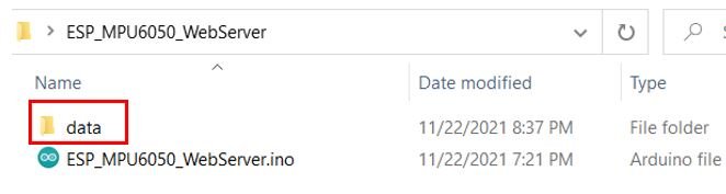
Before uploading the sketch to your ESP8266 board, first go to Sketch > Show Sketch Folder.
This will open up the folder where your Arduino sketch is saved. Now create a new folder inside that folder and save it as ‘data.’
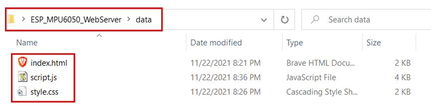
Place all the files inside the data folder. Otherwise, the LittleFS library will not be able to read them.
Now, we will upload the files to our ESP8266 board. Go to Tools > ESP8266 LittleFS Data Upload.
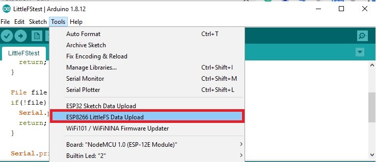
After a few moments, the files will be uploaded. You will receive the message ‘LittleFS Image Uploaded’ on the debugging window.
Note: Make sure that the total size of the data file is within the flash memory size. Otherwise you will get an error while uploading the files onto LittleFS.
Demonstration
Click on the upload button to upload the code to the ESP8266 development board.
After you have uploaded your code to the development board, press its ENABLE button.

In your Arduino IDE, open up the serial monitor and you will be able to see the IP address of your ESP8266 module.
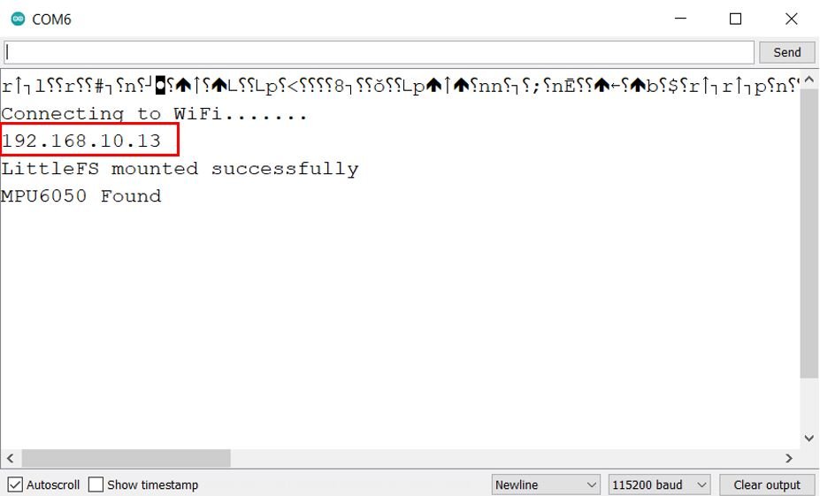
Type that IP address in a web browser and press enter. The web server will open up.
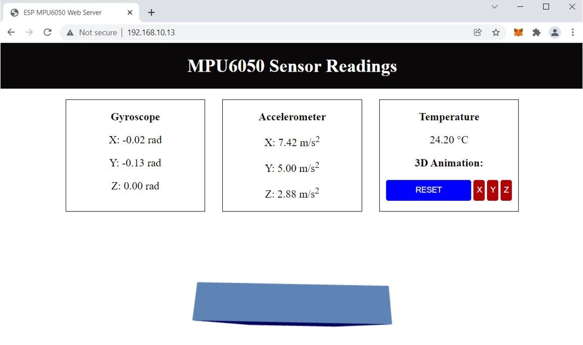
Now move your MPU6050 module and the 3D object will move in a similar manner. You will also be able to view the angular position, the acceleration, and the temperature in degrees Celsius.
You may also like to read:
- MPU6050 Gyroscope Accelerometer sensor interfacing with TM4C123G Tiva C Launchpad
- ESP32 Fall Detection using MPU6050 with Email Alerts
- MPU6050 with Arduino – Display values on SSD1306 OLED
- ESP32 with MPU6050 Accelerometer, Gyroscope, and Temperature Sensor ( Arduino IDE)
- MPU6050 Sensor Module Interfacing with Pic Microcontroller
hi , my ardunıo did not give me ip address . ı
uploaded code , no error but ı did not see serial monitor ıp adreess just “⸮⸮⸮⸮⸮⸮” ı give this .and ı dıd not see enable button
Ok, a couple things:
1) Your HTML file is missing tags around the URL at the beginning, and around the Script at the end. If you run the code as is, you just get text on the screen for those.
2) Was it also laggy as hell for you? I got it 99% to the way it is in the guy using the ESP32 youtube video. My trouble is that it only works if I constantly refresh the screen, and only for about a second. Serial monitor gives me sporadic “Client reconnected!” messages, and the object on screen moves (correctly) but briefly. I tried eliminating the Temperature functions to free up resources, but it doesn’t help much. I think the bottleneck is the ESP8266 itself not having the balls, but I’ve seen other people get it to work. Thoughts?
What I’ve done is to apply a delay(70) in the loop after every “if statement” and voila it works.
if ((millis() – previous_time_acceleration) > accelerometer_delay ) {
events.send(getAccelerationReadings().c_str(), “accelerometer_readings”, millis());
previous_time_acceleration = millis();
delay(70);
What I’m still struggling with is calibrating within the sketch, I can’t do that.
Hello, my name is Ger from the Netherlands and I have a short question. I am working on the project and it is a wonderful learning project for me. I am able to get the web server working but the HTML does not start. In other words, the page will remain blank. Do you maybe know where to look to get the page working.
Hi, I am not getting any values for the MPU6050. Just the HTML site. Seems the js is not running at all as I don have any 3D graphics either. Was this the same issue for you?
Can you check if you are getting MPU6050 found message on Arduino serial monitor?
I have the project “ESP8266 MPU6050 Web Server Accelerometer and Gyroscope Dashboard with 3D Animation (SSE Events)” running and running perfectly on the ESP8266. My problem is calibrating.
For example, if I rotate x rad or y rad to 15 then turning back rotates it 7, so the 3d model does not run synchronously.
Anyone know of a solution for this in the script?
Thanks and regards Ger
Hi Sir :
01:01:47.725 -> ⸮….
01:01:52.424 -> 192.168.0.105
01:01:52.752 -> MPU6050 Found
My problem is —– there is no “Connecting to WiFi” message , Could you help me where’s wrong? Thanks a lot .
Justin
Hi ive gotten everything to work even the javascript file and library in the index html file which didnt have the correct code documented. The only issue im having is with the events being disconnected and taking time to reconnect, this causes a big gap in the data and 3D objects movement. Above someone said to just put delays in the if statements however i dont really want to put anything in that would stop other parts of code from running, also i tried it and it just delays the inevitable disconnect anyway. Some things ive thought that could be the issue is maaybe the webserver on the ESP8266 has a full cache and causes it to stop for a while, maybe an issue with a buffer somewhere or it could be something to do with a library having a max speed or data output that is triggered.
Any help is appreciated thanks.
How can you fix it, can you please tell me
hi, i didn’t get the 3d cube in my web page
I got the Mpu6050 found and still dont see any value on the webserver