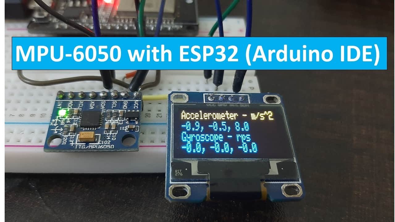
In this user guide, we will learn to interface MPU6050 with ESP32 using Arduino IDE. It is Accelerometer and a Gyroscope module used to measure acceleration, temperature, displacement, and angular velocity. It is equipped with 6-axis motion tracking sensors which are integrated inside MPU6050 the chip. This sensor provides data over the I2C protocol.
In this tutorial, we will see three examples of MPU-6050 with ESP32:
- Getting MPU-6050 Sensor Readings: Accelerometer, Gyroscope and Temperature
- ESP32 Display MPU-6050 Readings on Serial Plotter
- Displaying MPU-6050 Readings on OLED Display
We have similar guides with ESP8266 NodeMCU with Arduino IDE and MicroPython:
Recommended Components
The following components are used in this project or are helpful for building it with the ESP32.
| Component | How it’s used in this project | Buy on Amazon |
|---|---|---|
| ESP32 Development Board (DevKit V1) | The main board that runs the project firmware. | Check Price |
| Micro USB Cable | Connects the board to your computer to upload code and power it. | Check Price |
| Breadboard | Holds the board and components together while you wire up the project. | Check Price |
| Jumper Wires | Make the connections between the board and any external parts. | Check Price |
| MPU6050 accelerometer/gyroscope | The sensor read in this tutorial for acceleration, rotation and temperature over I2C. | Check Price |
As an Amazon Associate we earn from qualifying purchases. Prices and availability are accurate as of the date/time indicated and are subject to change.
MPU6050 Module Introduction
MPU6050 module consists of a digital motion that performs all complex processing, computations and provides sensor data output to other MCUs over I2C communication. It is widely used in measuring the health and operating parameters of various machines. It is also used in applications of robotics and motion sensors. This sensor is based on MEMS (Micro-Mechanical Systems) technology hence it is extremely compact and accurate in certain frequencies. It has a relatively small size and low power consumption. It communicates with other microcontrollers and sensors via I2C communication.
The module consists of 3-axis accelerometers, a 3-axis gyroscope, and a built-in temperature sensor. All of these are present on a single chip. The module takes into account the x, y, and z channels at the same time because it has 16 bits analog converter dedicated to each channel.
The 3-axis accelerometer measures the rate of change of velocity (m/s^2) or the acceleration of the object. This measurement can be performed on both stationary and moving objects. For stationary objects, the rate of change of velocity is equal to the gravitational acceleration (9.8 m/s^2) or gravity in short. The module also has a 3-axis gyroscope which measures the rotational velocity of an object in rad/s. This feature helps us understand the exact orientation of the object.
Features
Some of the key features of the MPU6050 Module include:
- Built-in I2C sensor bus which is used to provide gyroscope, accelerometer, and temperature sensor data to other devices such as microcontrollers.
- Onboard pull-up resistor so we do not need to connect external pull resistors which are a requirement for the I2C bus interface.
- User Programmable gyroscope and accelerometer with the help of 16-bit analog to digital converter.
- 1024 Byte FIFO buffer to provide data to the connected microcontroller in high speed and enters the low power mode afterwards.
- Built-in temperature sensor.
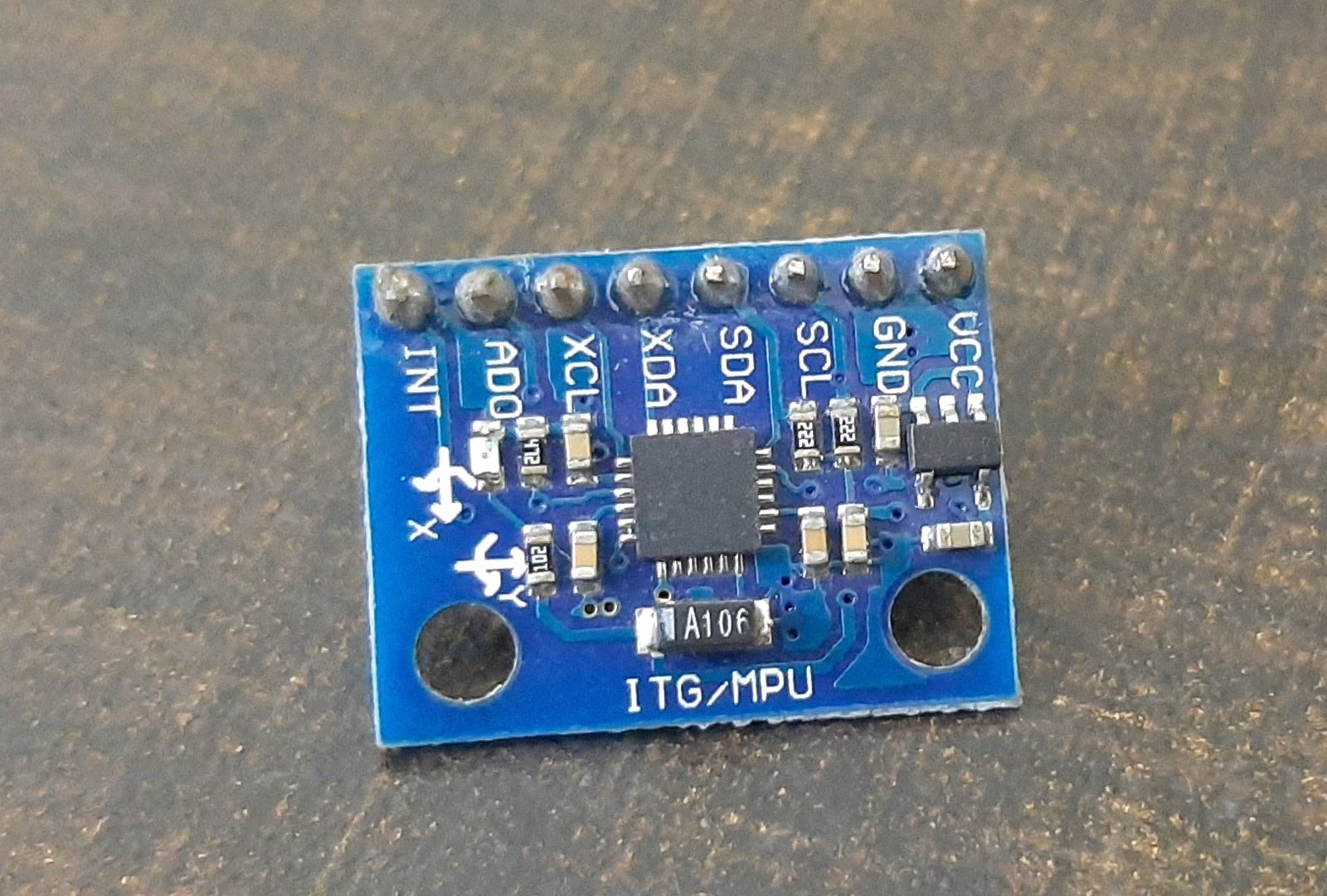
MPU6050 Pinout
Let’s look at the pinout of the MPU6050 Module below.
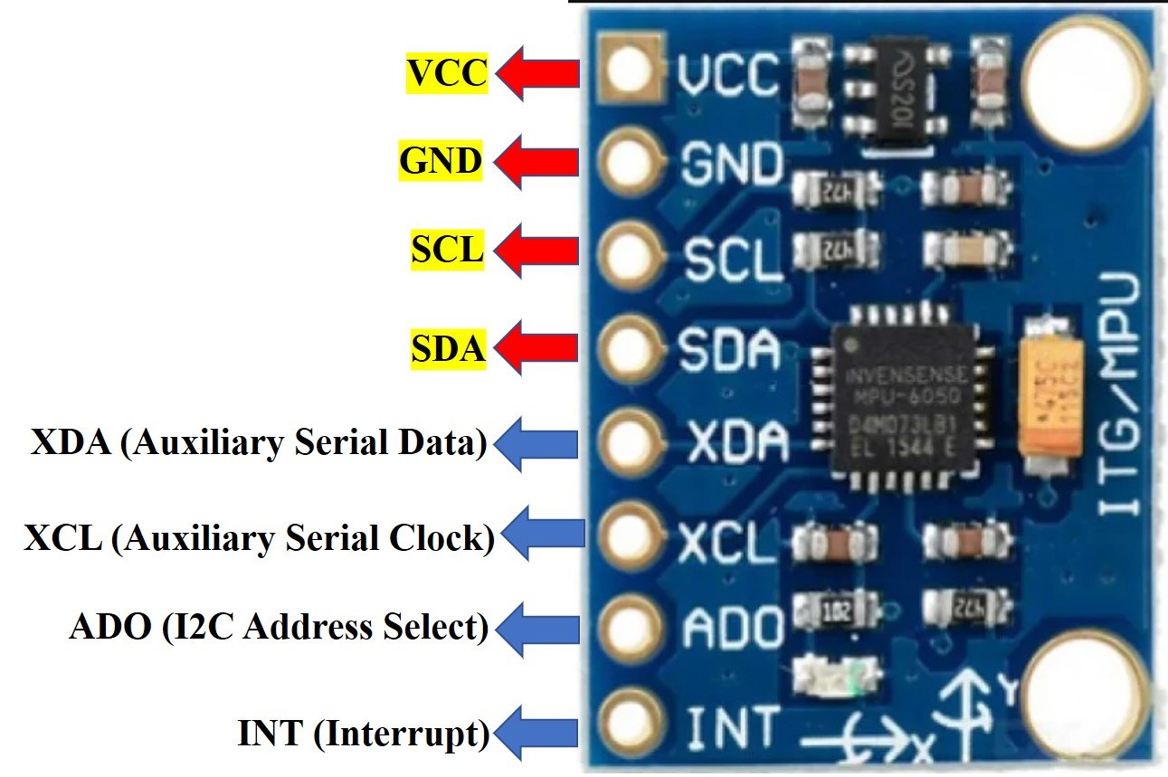
The table below shows a brief description for each pin.
| Pin Name | Description |
|---|---|
| VCC | This will power up the sensor. It can be in range 3.3-5V. |
| GND | This is the ground pin connected with the common ground. |
| SCL | This is the serial clock pin which is used in connecting with the microcontroller through its I2C pin. |
| SDA | This is the serial data pin which connects with the microcontroller’s I2C pin. |
| XDA | This is the auxiliary serial data pin which is used to connect other I2C sensors with the module. |
| XCL | This is the auxiliary serial clock pin which is used to connect other I2C sensors with the module. |
| ADO | This is the I2C address select pin. It is used in changing the I2C address. |
| INT | This is the interrupt pin. It could be used in distinguishing when a new measurement data is available. |
Install MPU6050 Arduino Library
We will be using Arduino IDE to program our ESP32 development board. Before we move ahead, make sure you have the latest version of Arduino installed on your computer. Moreover, you should have also an ESP32 add-on in Arduino IDE. You can check this tutorial:
To ensure the proper functionality of our project, we will first install the MPU6050 library in our IDE. There are many options for the MPU-6050 library for Arduino IDE. But we will use the Adafruit MPU6050 library. To use this library, two more libraries have to be installed as well, namely the Adafruit Unified Sensor library and the Adafruit Bus IO Library.
Follow the steps in order:
- First, click on Sketch > Include Library > Manage Libraries.
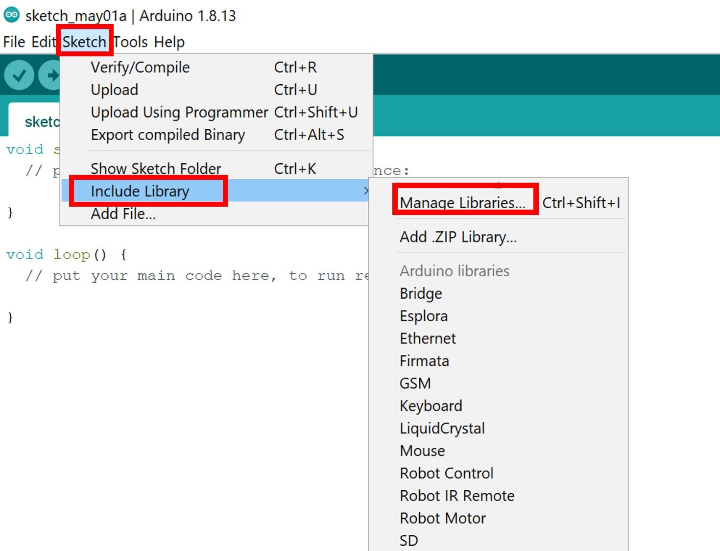
- The following window will open:

- As shown by the red arrow, type ‘adafruit mpu6050’ in the search bar. You will see the following library:
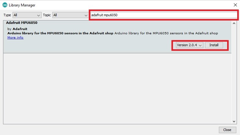
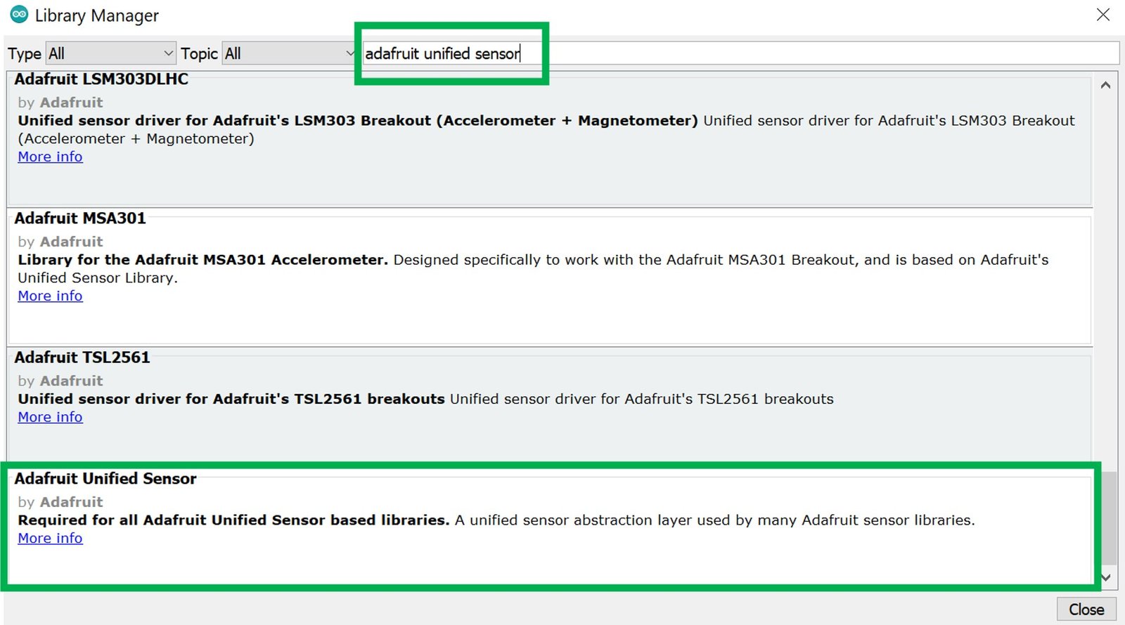
Click on the ‘Install’ button. After installing the ‘adafruit mpu6050’ search for ‘adafruit unified sensor.’ You will see several different libraries from this search. Go to the bottom of the search options and look for the following library highlighted in the green rectangle and install it.
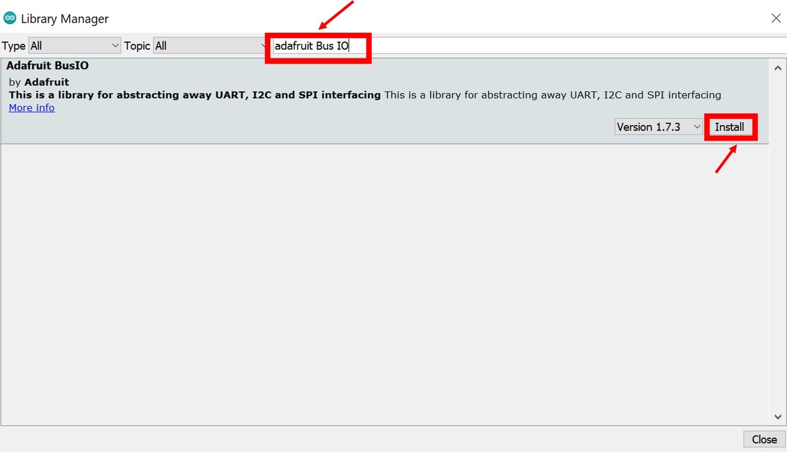
- Now we have to install the last library to ensure the proper functionality of the project. Type ‘adafruit Bus IO’ and install it as well.
Now restart your IDE. You will be able to access the MPU-6050 library functions to read Accelerometer, Gyroscope, and Temperature readings.
If you are using VS code with PlatformIO to program MPU-6050 with ESP32, you should add these commands to the platformio.ini to add the MPU-6050 library.
ESP32 Getting MPU-6050 Sensor Readings: Accelerometer, Gyroscope, and Temperature
In this section, we will see how to interface MPU-6050 with Arduino and get Accelerometer, Gyroscope, and Temperature readings from the sensor. We will display these readings on Arduino serial monitor.
MPU6050 Interfacing with ESP32
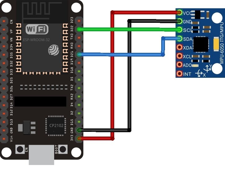
As you see, the MPU6050 has 8 terminals but in order to connect with ESP32, we will only require the first four pins highlighted in yellow. These are VCC, GND, SCL, and SDA. The table shows the connections between the two modules.
| MPU6050 Module | ESP32 Module |
|---|---|
| VCC | 3.3V |
| GND | GND (common ground) |
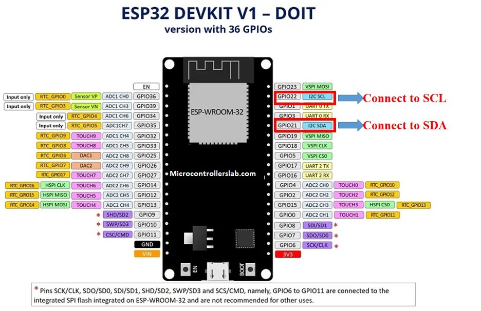
| SCL | GPIO22 (I2C SCL) |
| SDA | GPIO21 (I2C SDA) |
The VCC pin is connected with the 3.3V from the ESP32 module to power up. Both the grounds of the two devices are connected in common. The SCL pin of MPU6050 is connected with the default SCL pin of ESP32. Likewise, the SDA pin is connected with the default SDA pin of ESP32.
You can view the pinout of ESP32 below to get a better idea in making the connection.
Now, as we have seen how to connect the two modules together. Let’s look at a simple example to get sensor readings from the MPU-6050.
Required Components
We will be requiring the following components in this project.
- ESP32 development board
- MPU6050 Module
- Breadboard
- Connecting Wires
Assemble the two modules as shown below:
ESP32 Code: Getting MPU6050 Sensor Readings
Now, we will use the Adafruit MPU6050 library which we installed earlier to have a look at a simple code that would measure acceleration, angular velocity, and temperature from the sensor. There are many examples of codes available in the adafruit mpu6050 library. You can use any one of them to test your sensor. For this tutorial, we will select a simple example which displays sensor readings on the Arduino Serial monitor.
Open your Arduino IDE and go to File > Examples > Adafruit MPU6050 > basic_readings as shown in the figure below.
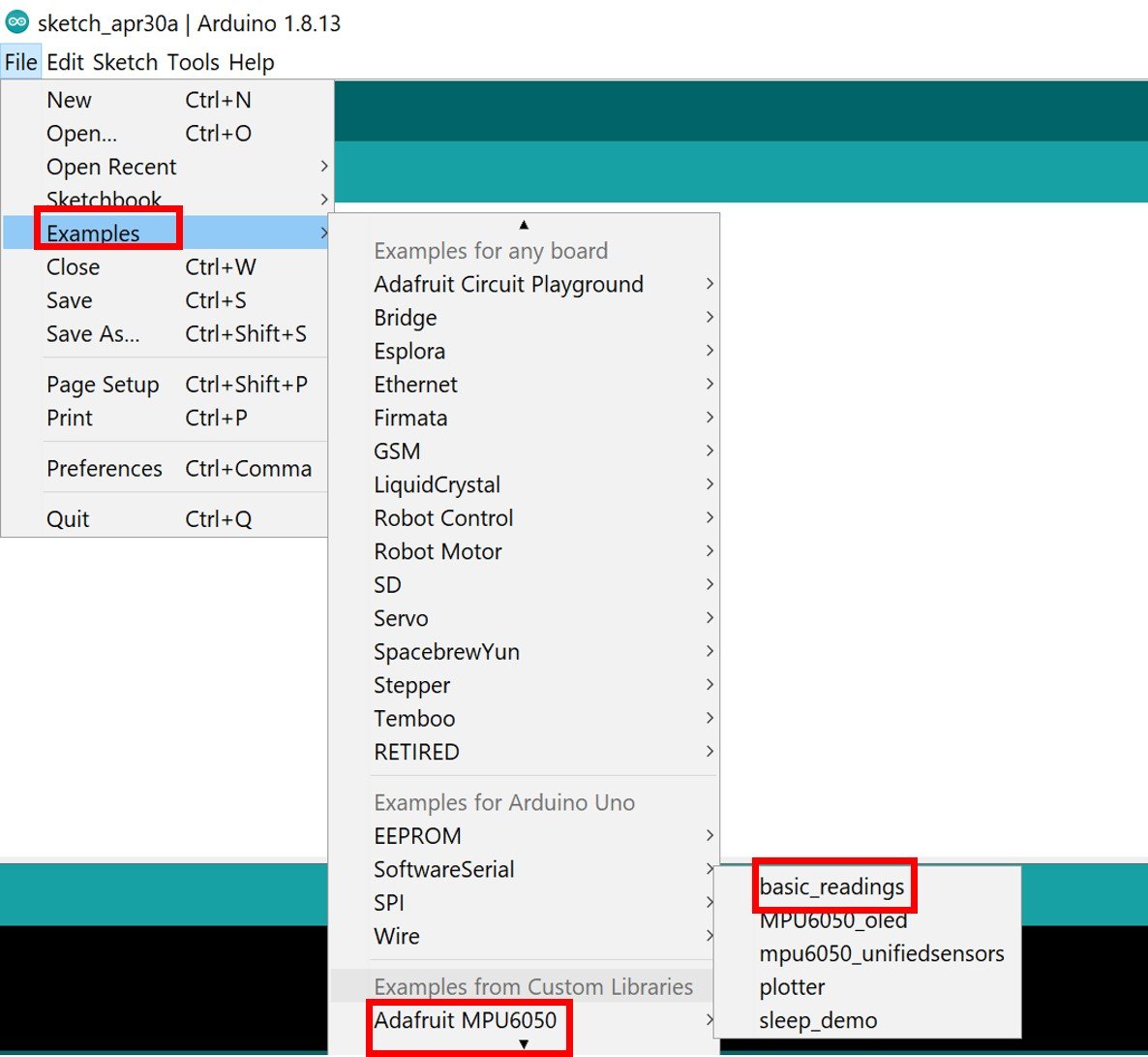
Another file will open up in your IDE which would contain the sample code for measuring the sensor readings. Copy the MPU-6050 code to your Arduino IDE and upload to ESP32 board.
// Basic demo for accelerometer readings from Adafruit MPU6050

#include <Adafruit_MPU6050.h>
#include <Adafruit_Sensor.h>
#include <Wire.h>

Adafruit_MPU6050 mpu;

void setup(void) {
  Serial.begin(115200);
  while (!Serial)
    delay(10); // will pause Zero, Leonardo, etc until serial console opens

  Serial.println("Adafruit MPU6050 test!");

  // Try to initialize!
  if (!mpu.begin()) {
    Serial.println("Failed to find MPU6050 chip");
    while (1) {
      delay(10);
    }
  }
  Serial.println("MPU6050 Found!");

  mpu.setAccelerometerRange(MPU6050_RANGE_8_G);
  Serial.print("Accelerometer range set to: ");
  switch (mpu.getAccelerometerRange()) {
  case MPU6050_RANGE_2_G:
    Serial.println("+-2G");
    break;
  case MPU6050_RANGE_4_G:
    Serial.println("+-4G");
    break;
  case MPU6050_RANGE_8_G:
    Serial.println("+-8G");
    break;
  case MPU6050_RANGE_16_G:
    Serial.println("+-16G");
    break;
  }
  mpu.setGyroRange(MPU6050_RANGE_500_DEG);
  Serial.print("Gyro range set to: ");
  switch (mpu.getGyroRange()) {
  case MPU6050_RANGE_250_DEG:
    Serial.println("+- 250 deg/s");
    break;
  case MPU6050_RANGE_500_DEG:
    Serial.println("+- 500 deg/s");
    break;
  case MPU6050_RANGE_1000_DEG:
    Serial.println("+- 1000 deg/s");
    break;
  case MPU6050_RANGE_2000_DEG:
    Serial.println("+- 2000 deg/s");
    break;
  }

  mpu.setFilterBandwidth(MPU6050_BAND_5_HZ);
  Serial.print("Filter bandwidth set to: ");
  switch (mpu.getFilterBandwidth()) {
  case MPU6050_BAND_260_HZ:
    Serial.println("260 Hz");
    break;
  case MPU6050_BAND_184_HZ:
    Serial.println("184 Hz");
    break;
  case MPU6050_BAND_94_HZ:
    Serial.println("94 Hz");
    break;
  case MPU6050_BAND_44_HZ:
    Serial.println("44 Hz");
    break;
  case MPU6050_BAND_21_HZ:
    Serial.println("21 Hz");
    break;
  case MPU6050_BAND_10_HZ:
    Serial.println("10 Hz");
    break;
  case MPU6050_BAND_5_HZ:
    Serial.println("5 Hz");
    break;
  }

  Serial.println("");
  delay(100);
}

void loop() {
  /* Get new sensor events with the readings */
  sensors_event_t a, g, temp;
  mpu.getEvent(&a, &g, &temp);

  /* Print out the values */
  Serial.print("Acceleration X: ");
  Serial.print(a.acceleration.x);
  Serial.print(", Y: ");
  Serial.print(a.acceleration.y);
  Serial.print(", Z: ");
  Serial.print(a.acceleration.z);
  Serial.println(" m/s^2");

  Serial.print("Rotation X: ");
  Serial.print(g.gyro.x);
  Serial.print(", Y: ");
  Serial.print(g.gyro.y);
  Serial.print(", Z: ");
  Serial.print(g.gyro.z);
  Serial.println(" rad/s");

  Serial.print("Temperature: ");
  Serial.print(temp.temperature);
  Serial.println(" degC");

  Serial.println("");
  delay(500);
}
How does the Code Work?
Let us understand how the sample code works. First, we are importing the libraries which we installed before in our Arduino IDE namely: Adafruit_MPU6050 and Adafruit_Sensor. The Adafruit_MPU6050 library is used in implementing the hardware functionalities of the sensor whereas the Adafruit_Sensor is a unified sensor library. The wire.h library is also being imported as it allows us to communicate via I2C. the I2Cprotocol is referred to as ‘wire’ in Arduino.
#include <Adafruit_MPU6050.h>
#include <Adafruit_Sensor.h>
#include <Wire.h>
Then, we will create an object named ‘mpu’ of Adafruit_MPU6050 to access the different functions of the sensor.
Adafruit_MPU6050 mpu;
Next, we will create the setup() function and pass no parameters inside. Inside the function, we first initiate the serial communication with the serial monitor with a baud rate of 115200 by using the begin() function.
Serial.begin(115200);Then we will be initializing the MPU6050 sensor by using an if statement to check whether the chip ID is correct or not. We will show the status on the serial monitor through a print command.
if (!mpu.begin()) {
    Serial.println("Failed to find MPU6050 chip");
    while (1) {
      delay(10);
    }
  }
  Serial.println("MPU6050 Found!");
Setting the Accelerometer Range
Next, we will set up sensitivity ranges for the sensor reading. First, we will look at the accelerometer range. The setAccelerometerRange() function takes in a single parameter specifying the range of the acceleration values. A smaller range determines a better sensitive outcome of reading which are obtained. We can choose between four options to set up as range which can be seen below.
- MPU6050_RANGE_2_G: specifies a range of ±2g. This is the default range
- MPU6050_RANGE_4_G: specifies a range of for ±4g.
- MPU6050_RANGE_8_G: specifies a range of for ±8g. This is the range which is being used in the code.
- MPU6050_RANGE_16_G: specifies a range of for ±16g.
mpu.setAccelerometerRange(MPU6050_RANGE_8_G);
  Serial.print("Accelerometer range set to: ");
  switch (mpu.getAccelerometerRange()) {
  case MPU6050_RANGE_2_G:
    Serial.println("+-2G");
    break;
  case MPU6050_RANGE_4_G:
    Serial.println("+-4G");
    break;
  case MPU6050_RANGE_8_G:
    Serial.println("+-8G");
    break;
  case MPU6050_RANGE_16_G:
    Serial.println("+-16G");
    break;
  }
Setting the Gyroscope range
Secondly, we will set the range for the gyroscope by using the setGyroRange() function. We can use one of the following parameters inside the function.
- MPU6050_RANGE_250_DEG: specifies 250 degrees-per-second range. This is set as the default.
- MPU6050_RANGE_500_DEG: specifies 500 degrees-per-second range.
- MPU6050_RANGE_1000_DEG: specifies 1000 degrees-per-second range.
- MPU6050_RANGE_2000_DEG: specifies 2000 degrees-per-second range.
 mpu.setGyroRange(MPU6050_RANGE_500_DEG);
  Serial.print("Gyro range set to: ");
  switch (mpu.getGyroRange()) {
  case MPU6050_RANGE_250_DEG:
    Serial.println("+- 250 deg/s");
    break;
  case MPU6050_RANGE_500_DEG:
    Serial.println("+- 500 deg/s");
    break;
  case MPU6050_RANGE_1000_DEG:
    Serial.println("+- 1000 deg/s");
    break;
  case MPU6050_RANGE_2000_DEG:
    Serial.println("+- 2000 deg/s");
    break;
  }
To get a more sensitive output response, set smaller degrees per second for the gyroscope range.
Setting the Low Pass Filter Bandwidth
We have to use a low pass filter on the gyroscope output. This is done to ensure all the unnecessary frequencies are filtered out and a smoother clean output is obtained. We will use the setFilterBandwidth() to pass a parameter which will allow us to change the cut-off frequency of the low pass filter. We will be setting the bandwidth of the filter by taking in one of the following frequencies as the parameter inside the function.
- MPU6050_BAND_260_HZ: specifies a 260 Hz bandthwidth
- MPU6050_BAND_184_HZ: specifies a 184 Hz bandthwidth
- MPU6050_BAND_94_HZ: specifies a 94 Hz bandthwidth
- MPU6050_BAND_44_HZ: specifies a 44 Hz bandthwidth
- MPU6050_BAND_21_HZ: specifies a 21 Hz bandthwidth
- MPU6050_BAND_10_HZ: specifies a 10 Hz bandthwidth
- MPU6050_BAND_5_HZ: specifies a 5 Hz bandthwidth
  mpu.setFilterBandwidth(MPU6050_BAND_5_HZ);
  Serial.print("Filter bandwidth set to: ");
  switch (mpu.getFilterBandwidth()) {
  case MPU6050_BAND_260_HZ:
    Serial.println("260 Hz");
    break;
  case MPU6050_BAND_184_HZ:
    Serial.println("184 Hz");
    break;
  case MPU6050_BAND_94_HZ:
    Serial.println("94 Hz");
    break;
  case MPU6050_BAND_44_HZ:
    Serial.println("44 Hz");
    break;
  case MPU6050_BAND_21_HZ:
    Serial.println("21 Hz");
    break;
  case MPU6050_BAND_10_HZ:
    Serial.println("10 Hz");
    break;
  case MPU6050_BAND_5_HZ:
    Serial.println("5 Hz");
    break;
  }
Obtaining the Sensor Readings & Displaying Them
Now, we will use loop() to obtain the sensor readings which displays on the serial monitor. We will start off by creating an object in memory named ‘sensors_event_t’ which will save our sensor readings for the accelerometer (a), gyroscope (g), and temperature (t).
sensors_event_t a, g, temp;Obtain new sensor events with current readings by using an object on the getEvent() function. We will call the getEvent() function which will get readings from the sensor and convert them into an appropriate International System of Units (SI).
mpu.getEvent(&a, &g, &temp);Then, we will print all the sensor readings which we obtained on the serial monitor. First, we will be displaying the Acceleration in m/s2. We will be displaying the acceleration on the x-axis, the y-axis, and the z-axis respectively. This is being accessed through a.acceleration.x, a.acceleration.y, and a.acceleration.z respectively.
Serial.print("Acceleration X: ");
Serial.print(a.acceleration.x);
Serial.print(", Y: ");
Serial.print(a.acceleration.y);
Serial.print(", Z: ");
Serial.print(a.acceleration.z);
Serial.println(" m/s^2");
The same applies to the sensor readings from the gyroscope which depict the angular velocity in rad/s. We will print the angular velocity on the x-axis the y axis and the z-axis respectively. This is being accessed through g.gyro.x, g.gyro.y and g.gyro.z respectively.
Serial.print("Rotation X: ");
Serial.print(g.gyro.x);
Serial.print(", Y: ");
Serial.print(g.gyro.y);
Serial.print(", Z: ");
Serial.print(g.gyro.z);
Serial.println(" rad/s");
Lastly, we will print the temperature in degree Celsius on the serial monitor. This is being accessed through temp.temperature.
Serial.print("Temperature: ");
Serial.print(temp.temperature);
Serial.println(" degC");
We are displaying the sensor readings after every 500 milliseconds.
delay(500);Demonstration ESP32 and MPU6050
To see the demonstration of the above code, upload the code to ESP32. But, before uploading code, make sure to select ESP32 board from Tools > Board and also select the correct COM port to which ESP32 board is connected from Tools > Port.
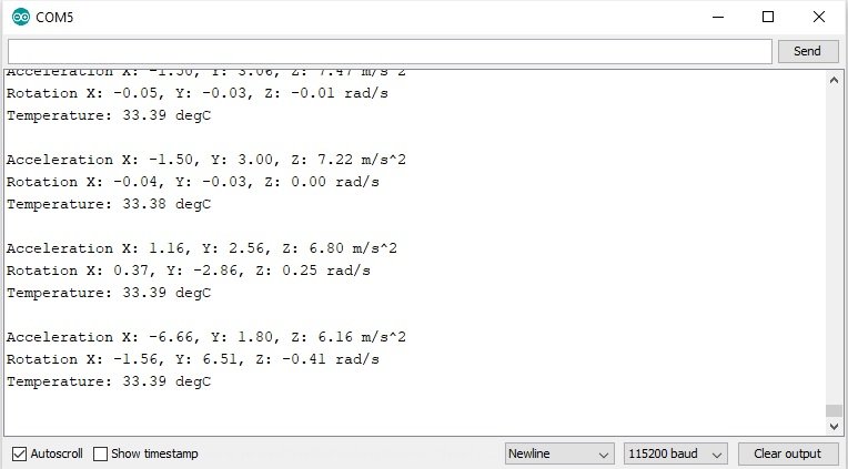
Once the code is uploaded to ESP32, open the serial monitor of Arduino IDE and set the baud rate to 115200. Finally, we can see the MPU-6050 readings on Arduino serial monitor.
Change MPU-6050 sensor direction, rotation and orientation to observe the change in values:
ESP32 Display MPU6050 Readings on Serial Plotter
In this section, we will see an example to plot MPU6050 readings using Arduino’s serial plotter. This example is exactly similar to the last one except it plots accelerometer and gyroscope readings on the X, Y, and Z-axis over time.
Open the sample code to plot MPU-6050 readings using Arduino’s serial plotter. Copy the MPU-6050 code to your Arduino IDE and upload it to the ESP32 board.
Demo
To see the demonstration of the above code, upload the code to ESP32. But, before uploading code, make sure to select ESP32 board from Tools > Board and also select the correct COM port to which ESP32 board is connected from Tools > Port.
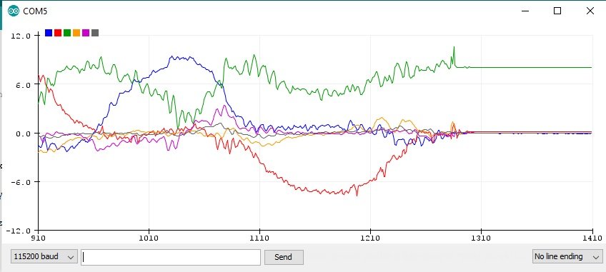
Once the code is uploaded to ESP32, open the serial plotter of Arduino IDE and set the baud rate to 115200. Finally, we can see the MPU-6050 readings on Arduino serial plotter.
Change MPU-6050 sensor direction, rotation and orientation to observe the change in values:
// Basic demo for accelerometer readings from Adafruit MPU6050

#include <Adafruit_MPU6050.h>
#include <Adafruit_Sensor.h>
#include <Wire.h>

Adafruit_MPU6050 mpu;

void setup(void) {
  Serial.begin(115200);
  while (!Serial) {
    delay(10); // will pause Zero, Leonardo, etc until serial console opens
  }

  // Try to initialize!
  if (!mpu.begin()) {
    Serial.println("Failed to find MPU6050 chip");
    while (1) {
      delay(10);
    }
  }

  mpu.setAccelerometerRange(MPU6050_RANGE_16_G);
  mpu.setGyroRange(MPU6050_RANGE_250_DEG);
  mpu.setFilterBandwidth(MPU6050_BAND_21_HZ);
  Serial.println("");
  delay(100);
}

void loop() {

  /* Get new sensor events with the readings */
  sensors_event_t a, g, temp;
  mpu.getEvent(&a, &g, &temp);

  /* Print out the values */
  Serial.print(a.acceleration.x);
  Serial.print(",");
  Serial.print(a.acceleration.y);
  Serial.print(",");
  Serial.print(a.acceleration.z);
  Serial.print(", ");
  Serial.print(g.gyro.x);
  Serial.print(",");
  Serial.print(g.gyro.y);
  Serial.print(",");
  Serial.print(g.gyro.z);
  Serial.println("");

  delay(10);
}
ESP32 Displaying MPU6050 Readings on OLED Display
Previously, we displayed the acceleration, angular velocity, and temperature readings on Arduino serial monitor. But to make this project more practical, we will learn how to print the Accelerometer, Gyroscope, and Temperature readings on an OLED display which would be connected with ESP32 development board and with the MPU6050 module. You will be requiring the following components:
Required Components
- ESP32 board
- MPU6050 sensor module
- 0.96-inch SSD 1306 MPU6050 module
- Breadboard
- Connecting Wires
Connecting OLED display with ESP32 & MPU-6050
The table below shows the terminals of the three devices which would be connected together.
| OLED Display | ESP32 | MPU-6050 |
|---|---|---|
| VCC | VCC=3.3V | VCC |
| GND | GND | GND |
| SCL | GPIO22 | SCL |
| SDA | GPIO21 | SDA |
Connection Diagram
Assemble the circuit as shown in the schematic diagram below

As you can see above, we have connected all the VCC terminals with a 3.3V power supply. The SCL terminals are connected with GPIO22 and the SDA terminals are connected with GPIO21. The grounds are also common.
Installing Adafruit SSD1306 OLED Library
To use the OLED display in our project, we have to install the Adafruit SSD 1306 library in Arduino IDE. Follow the steps below to successfully install it.
Open Arduino IDE and click on Sketch > Library > Manage Libraries
The following window will open up.
Type ‘SSD1306’ in the search tab and install the Adafruit SSD1306 OLED library.

You can read this in-depth guide on OLED interfacing with ESP32:
ESP32 Code: Displaying MPU6050 readings on OLED Display
We will be using the example code from Adafruit MPU6050 library. Click on File > Examples > Adafruit MPU6050 > MPU6050_oled

Another file will open up in your IDE which would contain the sample code for displaying the sensor readings on OLED. Copy the MPU-6050 code to your Arduino IDE and upload it to the ESP32 board.
#include <Adafruit_MPU6050.h>
#include <Adafruit_SSD1306.h>
#include <Adafruit_Sensor.h>

Adafruit_MPU6050 mpu;
Adafruit_SSD1306 display = Adafruit_SSD1306(128, 64, &Wire);

void setup() {
  Serial.begin(115200);
  // while (!Serial);
  Serial.println("MPU6050 OLED demo");

  if (!mpu.begin()) {
    Serial.println("Sensor init failed");
    while (1)
      yield();
  }
  Serial.println("Found a MPU6050 sensor");

  // SSD1306_SWITCHCAPVCC = generate display voltage from 3.3V internally
  if (!display.begin(SSD1306_SWITCHCAPVCC, 0x3C)) { // Address 0x3C for 128x64
    Serial.println(F("SSD1306 allocation failed"));
    for (;;)
      ; // Don't proceed, loop forever
  }
  display.display();
  delay(500); // Pause for 2 seconds
  display.setTextSize(1);
  display.setTextColor(WHITE);
  display.setRotation(0);
}

void loop() {
  sensors_event_t a, g, temp;
  mpu.getEvent(&a, &g, &temp);

  display.clearDisplay();
  display.setCursor(0, 0);

  Serial.print("Accelerometer ");
  Serial.print("X: ");
  Serial.print(a.acceleration.x, 1);
  Serial.print(" m/s^2, ");
  Serial.print("Y: ");
  Serial.print(a.acceleration.y, 1);
  Serial.print(" m/s^2, ");
  Serial.print("Z: ");
  Serial.print(a.acceleration.z, 1);
  Serial.println(" m/s^2");

  display.println("Accelerometer - m/s^2");
  display.print(a.acceleration.x, 1);
  display.print(", ");
  display.print(a.acceleration.y, 1);
  display.print(", ");
  display.print(a.acceleration.z, 1);
  display.println("");

  Serial.print("Gyroscope ");
  Serial.print("X: ");
  Serial.print(g.gyro.x, 1);
  Serial.print(" rps, ");
  Serial.print("Y: ");
  Serial.print(g.gyro.y, 1);
  Serial.print(" rps, ");
  Serial.print("Z: ");
  Serial.print(g.gyro.z, 1);
  Serial.println(" rps");

  display.println("Gyroscope - rps");
  display.print(g.gyro.x, 1);
  display.print(", ");
  display.print(g.gyro.y, 1);
  display.print(", ");
  display.print(g.gyro.z, 1);
  display.println("");

  display.display();
  delay(100);
}
How the Code works?
Include Libraries
We will first include all the required libraries for the MPU6050 sensor as well as the OLED display which we just installed before.
#include <Adafruit_MPU6050.h>
#include <Adafruit_SSD1306.h>
#include <Adafruit_Sensor.h>
Now, we will create an instance named ‘mpu’ of the Adafruit_MPU6050 library. This will be used in handling the sensor. We will also create another object named ‘display’ which will be handling the OLED display.
Adafruit_MPU6050 mpu;
Adafruit_SSD1306 display = Adafruit_SSD1306(128, 64, &Wire);
Then we will initialize the serial monitor at a baud rate of 115200 by using the setup() function.
Serial.begin(115200);The following code initializes the MPU6050 sensor:
if (!mpu.begin()) {
  Serial.println("Sensor init failed");
  while (1)
    yield();
}
This block of code initializes the OLED display.
// SSD1306_SWITCHCAPVCC = generate display voltage from 3.3V internally
if (!display.begin(SSD1306_SWITCHCAPVCC, 0x3C)) { // Address 0x3C for 128x64
  Serial.println(F("SSD1306 allocation failed"));
  for (;;)
    ; // Don't proceed, loop forever
}
display.display();
We have set the font size as default which is 1. Whenever we increase the size by +1, the pixel resolution of the text increases by 10 in height. Next, we will control the color of the text by using the setTextColor() function and passing WHITE as an argument. If we have a dark background, we will display our text in white and if we have a bright background then we will display the text in black. We do not want to rotate the text, so we are passing 0 as the parameter inside the setRotation() function. The parameter can take in any value from 0,1,2,3 where 0 denotes rotation of 0 degrees, 1 denotes rotation of 90 degrees, 2 denotes rotation of 180 degrees and 3 denotes a rotation of 270 degrees.
display.setTextSize(1);
display.setTextColor(WHITE);
display.setRotation(0);
The loop() obtains the readings from the sensors and prints them on the OLED display. We will first create events for the accelerometer (a), gyroscope (g), and temperature (t) and get their new sensor readings.
sensors_event_t a, g, temp;
mpu.getEvent(&a, &g, &temp);
clearDisplay() function wipes off the previous readings from the display after each loop() so that new ones can be printed.
display.clearDisplay();We will use setCursor() function to denote the x and the y axis position from where the text should start. We have passed (0,0) as the parameter hence the text starts from the upper left corner.
display.setCursor(0, 0);This block of code displays the accelerometer readings in x, y and z axis on the serial monitor.
Serial.print("Accelerometer ");
Serial.print("X: ");
Serial.print(a.acceleration.x, 1);
Serial.print(" m/s^2, ");
Serial.print("Y: ");
Serial.print(a.acceleration.y, 1);
Serial.print(" m/s^2, ");
Serial.print("Z: ");
Serial.print(a.acceleration.z, 1);
Serial.println(" m/s^2");
This block of code displays the accelerometer readings in x, y and z axis on the OLED display.
display.println("Accelerometer - m/s^2");
display.print(a.acceleration.x, 1);
display.print(", ");
display.print(a.acceleration.y, 1);
display.print(", ");
display.print(a.acceleration.z, 1);
display.println("");
This block of code displays the gyroscope readings in the x, y, and z axis on the serial monitor.
Serial.print("Gyroscope ");
Serial.print("X: ");
Serial.print(g.gyro.x, 1);
Serial.print(" rps, ");
Serial.print("Y: ");
Serial.print(g.gyro.y, 1);
Serial.print(" rps, ");
Serial.print("Z: ");
Serial.print(g.gyro.z, 1);
Serial.println(" rps");
This block of code displays the gyroscope readings in x, y and z axis on the OLED display.
display.println("Gyroscope - rps");
display.print(g.gyro.x, 1);
display.print(", ");
display.print(g.gyro.y, 1);
display.print(", ");
display.print(g.gyro.z, 1);
display.println("");
display.display();
After every 100 milliseconds, new sensor readings will be displayed.
delay(100);Demonstration ESP32, OLED and MPU6050
To see the demonstration of the above code, upload the code to ESP32. But, before uploading code, make sure to select ESP32 board from Tools > Board and also select the correct COM port to which ESP32 board is connected from Tools > Port.
Once the code is uploaded to ESP32, open the serial monitor of Arduino IDE and set the baud rate to 115200. Finally, we can see the MPU-6050 readings on Arduino serial monitor and on the OLED display as follows:

Video Demo:
We have similar guides for MPU6050 with other boards such as:
- MPU6050 Gyroscope Accelerometer sensor interfacing with TM4C123G Tiva C Launchpad
- MPU6050 Sensor Module Interfacing with Pic Microcontroller
- MicroPython: MPU-6050 with ESP32/ESP8266 (Accelerometer, Gyroscope, and temperature)
Other ESP32 Projects: