This tutorial shows how to interface the HC-SR04 ultrasonic sensor with Raspberry Pi Pico for contactless distance measurement using MicroPython. The HC-SR04 is a popular and low-cost ultrasonic distance sensor capable of measuring distances from 2 cm to 400 cm with an accuracy of approximately 3 mm. It operates at 5V and communicates using a simple two-pin digital interface, making it ideal for use with microcontrollers like the Raspberry Pi Pico.
First, we will learn how to interface the HC-SR04 with Raspberry Pi Pico. After that, we will see the MicroPython example code to measure distance and display it on the MicroPython terminal. Secondly, we will see a MicroPython example to display the measured distance (in cm) on an SSD1306 OLED display.
We have similar guides for ESP8266 and ESP32 using Arduino IDE:
- HC-SR04 Ultrasonic Sensor with ESP32 – Measure Distance
- HC-SR04 Ultrasonic Sensor with ESP8266 NodeMCU – Measure Distance
Recommended Components
The following components are used in this project or are helpful for getting started with Raspberry Pi Pico development.
| Component | How it’s used in this project | Buy on Amazon |
|---|---|---|
| Raspberry Pi Pico | The RP2040 microcontroller board used in this tutorial. | Check Price |
| HC-SR04 Ultrasonic Sensor | HC-SR04 ultrasonic distance sensor. | Check Price |
| Breadboard | Solderless breadboard for building the circuit. | Check Price |
| Jumper Wires | Male-to-male / male-to-female wires for the connections. | Check Price |
As an Amazon Associate we earn from qualifying purchases. Prices and availability are accurate as of the date/time indicated and are subject to change.
Prerequisites
Before starting this lesson, make sure you are familiar with Python 3 and have the latest version installed on your system. You should also have MicroPython set up on your Raspberry Pi Pico and have a working Integrated Development Environment (IDE). We will be using Thonny IDE, which we have used in previous tutorials. If you have not followed our previous tutorials, you can check them here:
If you are using uPyCraft IDE, you can check this getting started guide:
HC-SR04 Ultrasonic Sensor Introduction
The HC-SR04 is one of the most widely used ultrasonic distance sensors in embedded systems and robotics projects. It is affordable, easy to use, and provides reliable non-contact distance measurements. The sensor can measure distances ranging from 2 cm to 400 cm (4 meters) with an accuracy of about 3 mm. It operates at a supply voltage of 5V and draws a current of approximately 15 mA during operation.
One important consideration when using the HC-SR04 with the Raspberry Pi Pico is the voltage level difference. The HC-SR04 operates at 5V and its Echo pin outputs a 5V signal. However, the Raspberry Pi Pico’s GPIO pins are only 3.3V tolerant. To safely connect the Echo pin to the Pico, you should use a voltage divider (two resistors: e.g., 1kΩ and 2kΩ) or a logic level converter to step down the 5V Echo signal to 3.3V. The Trigger pin is safe to connect directly since it is an input driven by the Pico’s 3.3V output.
To interface the HC-SR04 ultrasonic sensor with Raspberry Pi Pico, we need to understand the functionality of each pin. Knowing the purpose of the input and output pins helps us identify which GPIO pins of the Raspberry Pi Pico should be used.
HC-SR04 Pinout
The figure below shows the pin configuration of the HC-SR04 ultrasonic sensor. It has four pins: VCC, GND, Trigger, and Echo.
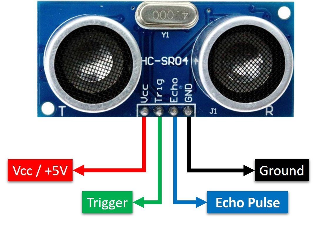
VCC: Power supply pin. Connect to 5V (the VSYS pin on Raspberry Pi Pico when powered via USB provides 5V).
GND: Ground pin. Connect to the GND of the Raspberry Pi Pico.
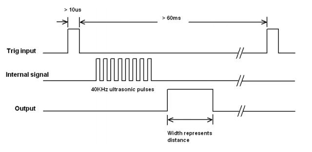
Trigger: This is a digital input pin. A 10 microsecond (10µs) HIGH pulse applied to this pin causes the sensor to emit a burst of ultrasonic waves. The Raspberry Pi Pico sends this trigger signal from a GPIO output pin.
Echo: This is a digital output pin from the sensor. It goes HIGH when the ultrasonic burst is sent and goes LOW when the reflected signal is received. The duration for which this pin remains HIGH corresponds to the travel time of the ultrasonic pulse, which is then used to calculate distance. Note that this pin outputs a 5V signal, so take care to protect the Pico’s 3.3V GPIO input.
How HC-SR04 Sensor Works?
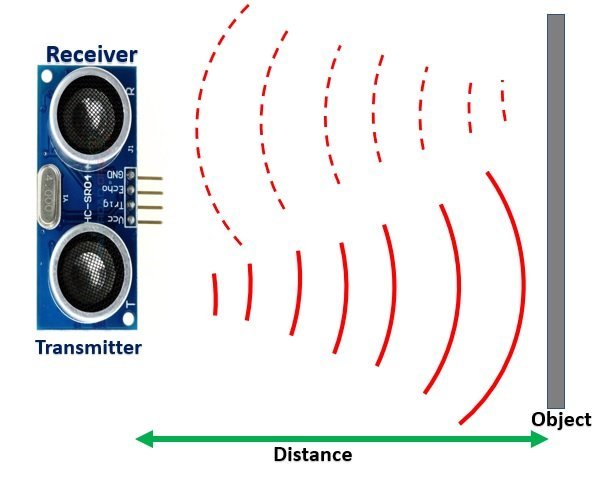
The HC-SR04 ultrasonic sensor measures distance by emitting inaudible ultrasonic sound waves at a frequency of 40 kHz. These waves travel through the air, and when they hit an object, they reflect back toward the sensor. The sensor measures the time it takes for the echo to return and uses that time to calculate the distance to the object.
For accurate measurements, the object should ideally be placed directly in front of the sensor, parallel to its face. This ensures that the reflected waves return at an angle of 180 degrees relative to the transmitted waves.
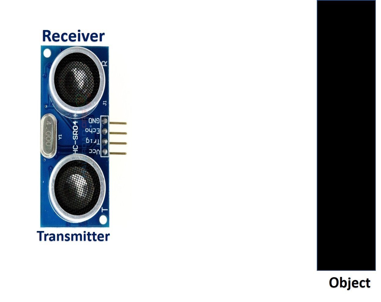
The HC-SR04 consists of two main modules: an ultrasonic transmitter and an ultrasonic receiver. The transmitter converts an electrical signal into a 40 kHz burst of 8 ultrasonic sonar pulses when it receives a 10µs trigger pulse on its Trigger pin. The receiver circuit listens for the reflected waves and drives the Echo pin HIGH upon transmission and LOW once the echo is received.
Measure HC-SR04 Echo Pulse Time with Raspberry Pi Pico
Here is the step-by-step process of how the HC-SR04 measures distance when used with Raspberry Pi Pico:
- The Raspberry Pi Pico sends a 10µs HIGH pulse to the Trigger pin of the HC-SR04 sensor from a GPIO output pin.
- Once the trigger pulse ends (goes LOW), the transmitter circuit emits a burst of 8 ultrasonic sonar pulses. At the same time, the Echo pin transitions from LOW to HIGH.
- The Raspberry Pi Pico starts measuring time as soon as the Echo pin goes HIGH, using MicroPython’s
machine.time_pulse_us()function. - The ultrasonic waves travel through the air. If an object is placed in front of the sensor, the waves reflect off its surface and travel back toward the sensor.
- When the receiver circuit detects the returning echo, the Echo pin goes LOW. The Raspberry Pi Pico detects this HIGH-to-LOW transition and stops measuring time.
By measuring the duration for which the Echo pin remained HIGH, we can determine how far the ultrasonic pulse traveled and calculate the distance to the object.
The longer the Echo pulse duration, the farther the object is from the sensor. This is because ultrasonic waves travel at the speed of sound (approximately 343 m/s at room temperature), which is constant. A larger distance means the pulse takes longer to return to the receiver.
How to Convert Time Duration into Distance
Once we have measured the Echo pulse duration (in microseconds), we can convert it to a physical distance using the basic speed-distance-time formula:
Distance (S) = Speed (v) * Time (t) // distance in metersHere, v is the speed of sound in air, which is approximately 340 m/s. Since the ultrasonic pulse travels from the sensor to the object and back again, we need to divide the total time by 2 to get the one-way travel distance:
S = (34000 * t) / 2 // distance in cm, where t is in secondsSimplifying this gives us:
S = 17000 * t // distance in cmNote: You do not need to worry about these calculations manually. The MicroPython library for HC-SR04 handles all distance computation internally and returns ready-to-use values in cm or mm.
How to Interface HC-SR04 Ultrasonic Sensor with Raspberry Pi Pico?
Now that we understand how the HC-SR04 sensor works and its pin functions, we can connect it to the Raspberry Pi Pico. The connection requires four wires: two for power (VCC and GND) and two for data (Trigger and Echo). The Trigger pin connects to a GPIO output on the Pico, and the Echo pin connects to a GPIO input.
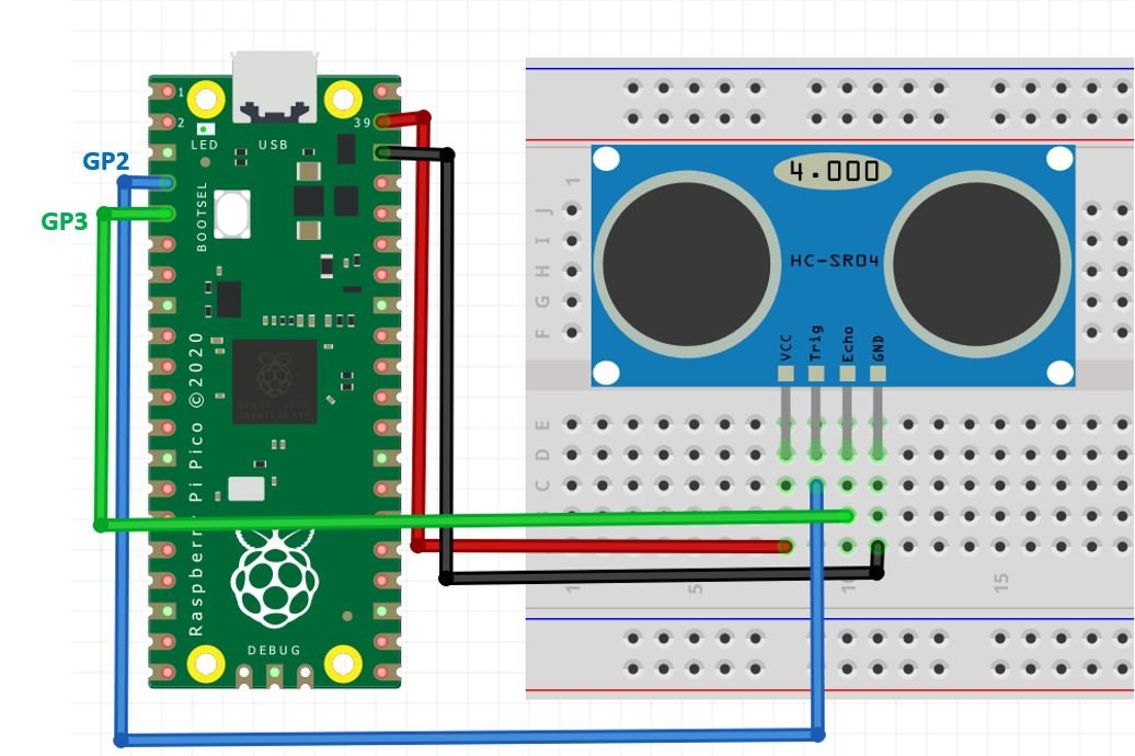
Make the connections between the Raspberry Pi Pico and the HC-SR04 sensor according to the table below:
| HC-SR04 | Raspberry Pi Pico |
| VCC | VSYS (5V) |
| GND | GND |
| Trigger | GP2 |
| Echo | GP3 |
HC-SR04 MicroPython Library
By default, MicroPython does not include a built-in driver for the HC-SR04 sensor. However, there is a community-developed library that makes it easy to use the sensor without implementing the timing logic from scratch. The library is available on GitHub and can be downloaded from this link.
Download the library file and upload it to your Raspberry Pi Pico board with the filename hcsr04.py, ideally inside a lib folder. The library provides two convenient methods: distance_cm() for reading distance in centimeters (as a float) and distance_mm() for distance in millimeters (as an integer, with no floating-point operations).
The echo_timeout_us parameter in the HCSR04 constructor sets the maximum time (in microseconds) to wait for an echo. If no echo is received within this time, the library raises an OSError('Out of range') exception. The default value is calculated based on the sensor’s maximum range of 400 cm. In the examples below, we set it to 10000 µs (10 ms) which corresponds to a range of about 170 cm.
import machine, time
from machine import Pin

__version__ = '0.2.0'
__author__ = 'Roberto Sánchez'
__license__ = "Apache License 2.0. https://www.apache.org/licenses/LICENSE-2.0"

class HCSR04:
    """
    Driver to use the untrasonic sensor HC-SR04.
    The sensor range is between 2cm and 4m.
    The timeouts received listening to echo pin are converted to OSError('Out of range')
    """
    # echo_timeout_us is based in chip range limit (400cm)
    def __init__(self, trigger_pin, echo_pin, echo_timeout_us=500*2*30):
        """
        trigger_pin: Output pin to send pulses
        echo_pin: Readonly pin to measure the distance. The pin should be protected with 1k resistor
        echo_timeout_us: Timeout in microseconds to listen to echo pin.
        By default is based in sensor limit range (4m)
        """
        self.echo_timeout_us = echo_timeout_us
        # Init trigger pin (out)
        self.trigger = Pin(trigger_pin, mode=Pin.OUT, pull=None)
        self.trigger.value(0)

        # Init echo pin (in)
        self.echo = Pin(echo_pin, mode=Pin.IN, pull=None)

    def _send_pulse_and_wait(self):
        """
        Send the pulse to trigger and listen on echo pin.
        We use the method `machine.time_pulse_us()` to get the microseconds until the echo is received.
        """
        self.trigger.value(0) # Stabilize the sensor
        time.sleep_us(5)
        self.trigger.value(1)
        # Send a 10us pulse.
        time.sleep_us(10)
        self.trigger.value(0)
        try:
            pulse_time = machine.time_pulse_us(self.echo, 1, self.echo_timeout_us)
            return pulse_time
        except OSError as ex:
            if ex.args[0] == 110: # 110 = ETIMEDOUT
                raise OSError('Out of range')
            raise ex

    def distance_mm(self):
        """
        Get the distance in milimeters without floating point operations.
        """
        pulse_time = self._send_pulse_and_wait()
        mm = pulse_time * 100 // 582
        return mm

    def distance_cm(self):
        """
        Get the distance in centimeters with floating point operations.
        It returns a float
        """
        pulse_time = self._send_pulse_and_wait()
        cms = (pulse_time / 2) / 29.1
        return cms
MicroPython HC-SR04 Ultrasonic Sensor Raspberry Pi Pico Code
After uploading the HC-SR04 library to the Raspberry Pi Pico board, we can use the functions provided by the library to read sensor data.
HC-SR04 MicroPython Example
The following MicroPython script reads the distance from the HC-SR04 sensor and prints it on the MicroPython shell console every second. Copy this code to a file named main.py and upload it to the Raspberry Pi Pico.
from hcsr04 import HCSR04
from time import sleep

sensor = HCSR04(trigger_pin=2, echo_pin=3, echo_timeout_us=10000)

while True:
    try:
        distance = sensor.distance_cm()
        print('Distance:', distance, 'cm')
    except OSError as e:
        print('Error:', e)
    sleep(1)
How the Code Works?
Importing Libraries
We start by importing the HCSR04 class from the hcsr04 library and the sleep function from the time module.
from hcsr04 import HCSR04
from time import sleep
Defining Raspberry Pi Pico GPIO Pins for HC-SR04
We create an object of the HCSR04 class named sensor. The first argument, trigger_pin=2, specifies that GPIO2 is used to send the trigger signal to the sensor. The second argument, echo_pin=3, specifies that GPIO3 will read the echo response. The third argument, echo_timeout_us=10000, sets the maximum wait time for an echo to 10,000 microseconds (10 ms), which corresponds to a maximum detection range of approximately 170 cm.
sensor = HCSR04(trigger_pin=2, echo_pin=3, echo_timeout_us=10000)Getting HC-SR04 Sensor Values
Inside the infinite while loop, we call sensor.distance_cm() to get the measured distance in centimeters and store it in the distance variable. We wrap the call in a try/except block to handle the case where the sensor returns an “Out of range” error (when no object is detected within the configured timeout).
distance = sensor.distance_cm()The measured distance is then printed to the MicroPython shell console, and the loop pauses for 1 second before taking the next reading.
print('Distance:', distance, 'cm')
sleep(1)
Demo
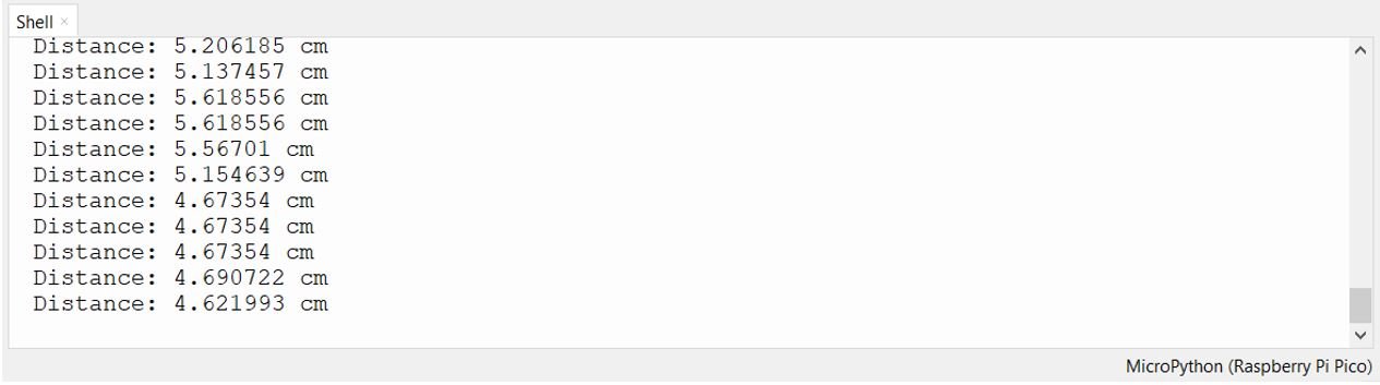
To test the MicroPython script, upload the main.py file to your Raspberry Pi Pico. Open the Thonny IDE shell console and you will see the distance value printed every second as shown below:
Troubleshooting Common Issues
If you encounter problems while using the HC-SR04 with Raspberry Pi Pico, here are the most common issues and how to resolve them:
Reading of -0.034 cm consistently: This is the most commonly reported problem. It almost always indicates a loose or broken wire connection. If no echo signal is detected (because the sensor is not connected), the pulse time returns a near-zero or negative value, which the library converts to approximately -0.034 cm. Check all wires carefully on your breadboard, as breadboard contacts are often unreliable. Try replacing the jumper wires or pressing the sensor pins more firmly into the board.
“Out of range” OSError exception: This exception is raised when the Echo pin does not return to LOW within the configured echo_timeout_us period. This can happen when the object is too far away, angled away from the sensor, or when nothing is in front of the sensor. You can either increase the echo_timeout_us value or wrap your sensor call in a try/except block to handle this gracefully.
Erratic or fluctuating readings: Unstable readings are often caused by electrical noise on the power supply line. Try adding a 100nF decoupling capacitor across the VCC and GND pins of the HC-SR04. Additionally, keep the sensor wiring short and away from high-frequency signal lines.
Trigger and Echo pins swapped: If the code runs without error but readings are always zero or out of range, verify that the Trigger and Echo wires are not swapped. The Trigger pin (GP2) must be connected to the Trigger pin of the HC-SR04, and the Echo pin (GP3) to the Echo pin.
Practical Applications
The HC-SR04 ultrasonic sensor is versatile and used in a wide range of real-world applications. Here are some popular projects you can build using the HC-SR04 and Raspberry Pi Pico:
Robot obstacle avoidance: Mount the sensor on a robot and use it to detect obstacles in its path. When an object is detected within a threshold distance (e.g., 20 cm), the robot can stop or change direction automatically.
Water tank level monitoring: Mount the sensor above a water tank pointing downward. The sensor measures the distance from its position to the water surface, which can be used to calculate the current water level and trigger alerts when the level is too low or too high.
Smart parking sensor: Use the HC-SR04 to detect whether a parking space is occupied. When a car is parked within a certain distance, an LED or buzzer can signal that the space is taken.
Touchless object counter: Position the sensor across a conveyor belt or doorway. Each time an object passes and interrupts the ultrasonic beam (causing a sudden change in distance), the counter increments. This is useful for counting items on a production line or people entering a room.
MicroPython: Displaying HC-SR04 Sensor Values on OLED Display
In this section, we will see how to display the measured distance on a 0.96-inch SSD1306 OLED display using MicroPython and Raspberry Pi Pico.
You can find more information about using an OLED with Raspberry Pi Pico here:
SSD1306 OLED Display MicroPython Library
To use the OLED display, we need to install the micropython-ssd1306 library on the Raspberry Pi Pico.
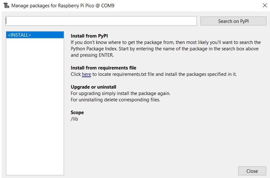
- Open Thonny IDE with your Raspberry Pi Pico connected. Go to Tools > Manage Packages to open the Thonny Package Manager.
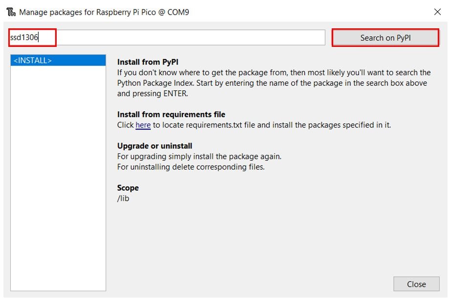
- Type ssd1306 in the search bar and click Search on PyPI.
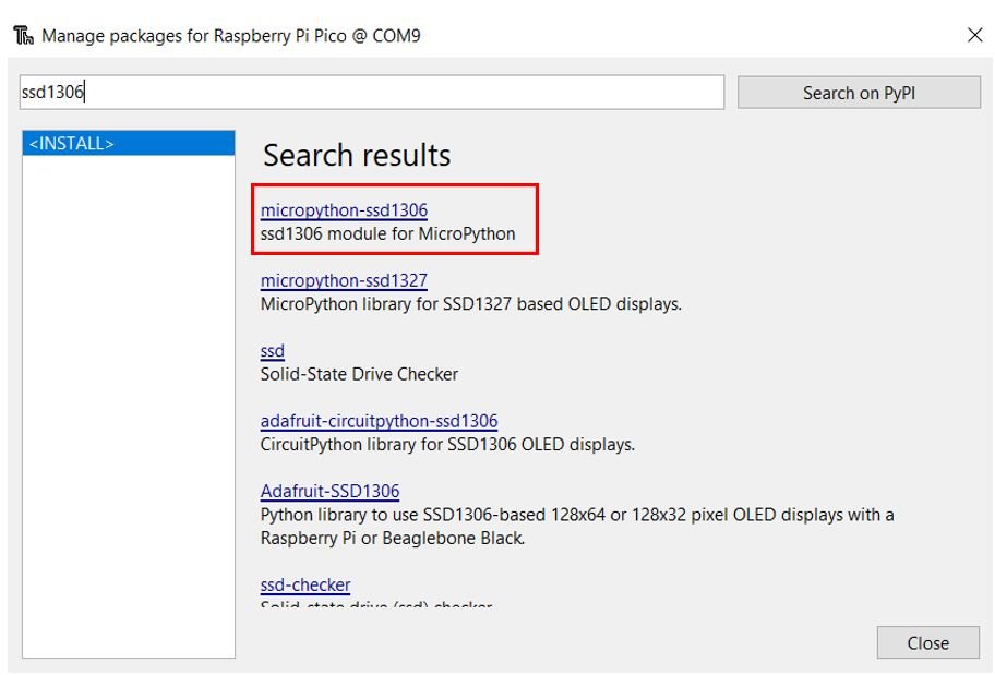
- From the search results, select micropython-ssd1306.
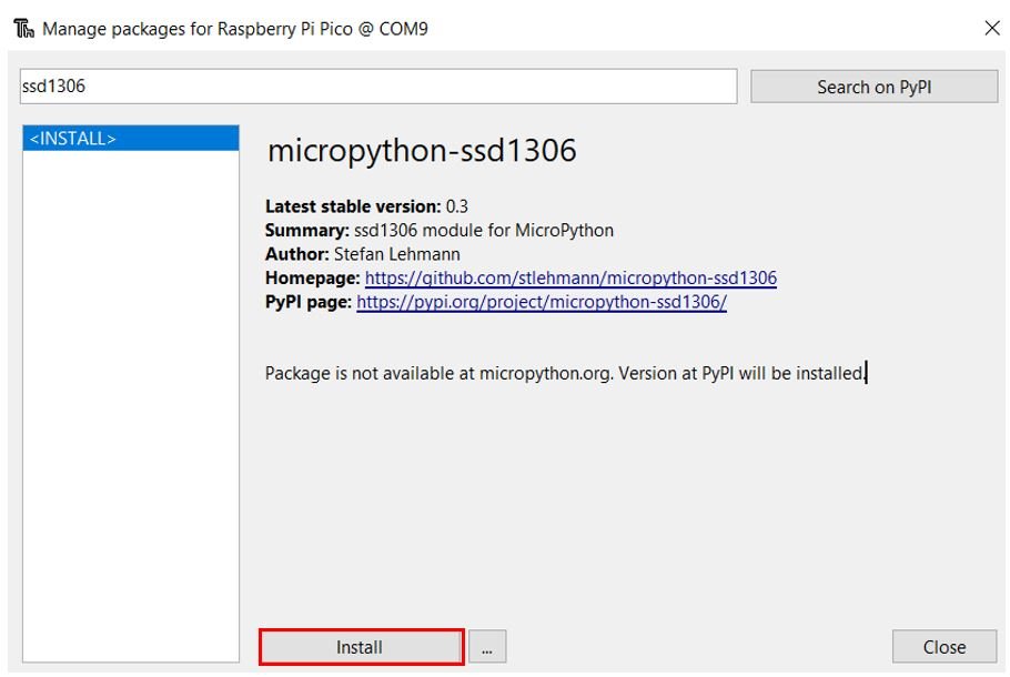
Click Install and wait for the installation to complete.
Once the library is installed successfully, you are ready to use the OLED display with your Raspberry Pi Pico.
Connecting SSD1306 OLED Display with Raspberry Pi Pico and HC-SR04
You will need the following components for this section:
- Raspberry Pi Pico
- HC-SR04 Ultrasonic Sensor
- SSD1306 OLED Display (0.96 inch, I2C)
- Jumper Wires
- Breadboard
The OLED display communicates over the I2C bus and requires only four connections to the Raspberry Pi Pico. The VCC pin of the OLED is connected to the 5V (VSYS) pin of the Pico (shared with the HC-SR04 VCC). The SDA and SCL lines connect to the I2C0 SDA and SCL pins of the Pico. All three devices (Pico, HC-SR04, OLED) share a common GND.
| SSD1306 OLED Display | Raspberry Pi Pico |
| VCC | 5V (VSYS) |
| SDA | GP0 (I2C0 SDA) |
| SCL | GP1 (I2C0 SCL) |
| GND | GND |
| HC-SR04 | Raspberry Pi Pico |
| VCC | 5V (VSYS) |
| GND | GND |
| Trigger | GP2 |
| Echo | GP3 |
Schematic: Raspberry Pi Pico with OLED and HC-SR04
Follow the schematic diagram below and connect the components accordingly:
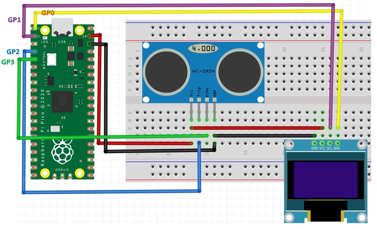
MicroPython Code: Displaying HC-SR04 Distance on OLED Display
from machine import Pin, I2C
from hcsr04 import HCSR04
from time import sleep
from ssd1306 import SSD1306_I2C

sensor = HCSR04(trigger_pin=2, echo_pin=3, echo_timeout_us=10000)

i2c = I2C(0, sda=Pin(0), scl=Pin(1), freq=400000)  # Initialize I2C
oled = SSD1306_I2C(128, 64, i2c)

while True:
    oled.fill(0)
    try:
        distance = str(round(sensor.distance_cm(), 2))
        oled.text("Distance", 0, 15)
        oled.text(distance + " cm", 0, 35)
    except OSError:
        oled.text("Out of range", 0, 25)
    oled.show()
    sleep(1)
How Does the Code Work?
In this section, we explain the part of the MicroPython code that handles the OLED display. The sensor reading logic is the same as in the previous example.
We import the SSD1306_I2C class from the ssd1306 library along with the Pin and I2C classes from the machine module. These are needed to initialize the I2C bus and control the OLED display.
from machine import Pin, I2C
from ssd1306 import SSD1306_I2C
We initialize the I2C0 bus with SDA on GP0 and SCL on GP1, running at 400 kHz. Then we create an oled object using a resolution of 128×64 pixels.
i2c = I2C(0, sda=Pin(0), scl=Pin(1), freq=400000)
oled = SSD1306_I2C(128, 64, i2c)
In the main loop, we clear the display with oled.fill(0), then attempt to read the distance. If successful, we display the distance value rounded to 2 decimal places. If an OSError is raised (out of range), we display an “Out of range” message instead. Finally, oled.show() is called to push the changes to the display.
oled.fill(0)
try:
distance = str(round(sensor.distance_cm(), 2))
oled.text("Distance", 0, 15)
oled.text(distance + " cm", 0, 35)
except OSError:
oled.text("Out of range", 0, 25)
oled.show()
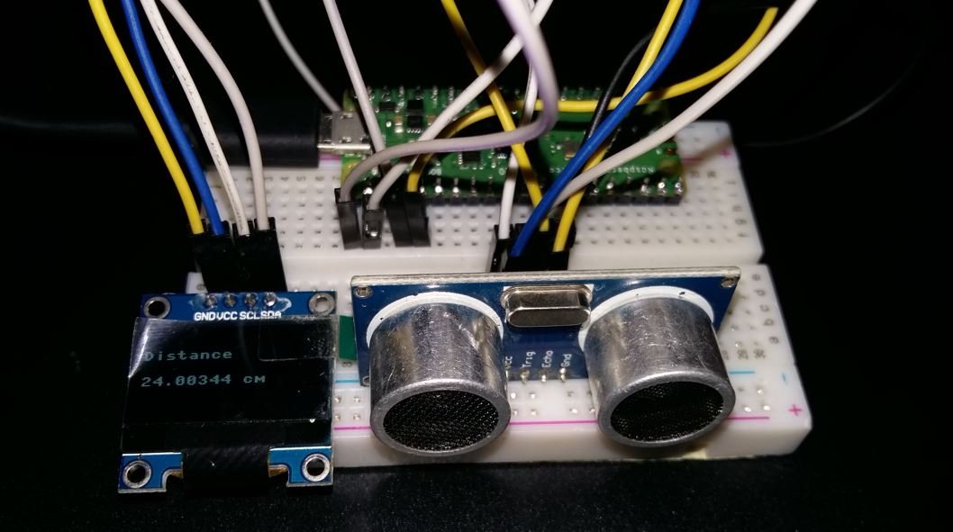
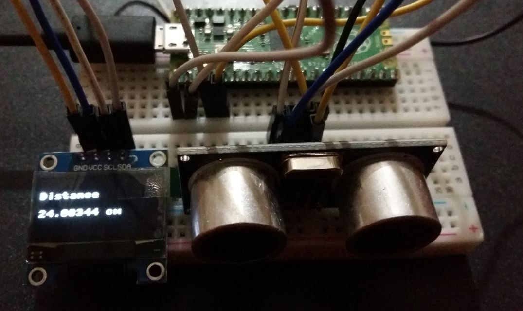
sleep(1)Demonstration
Upload the code above as main.py to your Raspberry Pi Pico. You will see the HC-SR04 distance readings displayed on the OLED screen as shown below:
We have other guides with popular sensors:
- MPU6050 with Raspberry Pi Pico (Accelerometer, Gyroscope, and Temperature)
- BME280 with Raspberry Pi Pico using MicroPython
- DHT11 DHT22 with Raspberry Pi Pico using MicroPython
- DS18B20 Temperature Sensor with Raspberry Pi Pico using MicroPython
Related HC-SR04 tutorials:
you talk about hooking VCC to 5 V but the PICO has an output of 3.3 volt. Is this the reason I get a reading of -0.03436426 cm in all the readings?
VBUS: is the micro-USB input voltage it is connected to micro-USB port pin 1. So if the input is 5V, the output is 5V.
VSYS: is the main system input voltage, which can vary in the allowed range 1.8V to 5.5V, and is used by the on-board
I also have a repeated -0.034… cm as return but haven’t solved the problem yet.
solved it. so the problem (with me at least) was that the connection to the sensor was not complete (the breadboard sucks). so try to check the connection wires. when you don’t connect the sensor at all you will get -0.0343… hope it helps!