This tutorial shows how to interface HC-SR04 ultrasonic sensors with ESP32 and ESP8266 NodeMCU for contactless distance measurement using MicroPython. First, we will learn to interface HC-SR04 with ESP32 and ESP8266 NodeMCU. After that, we will see the MicroPython example code to measure distance and display it on the MicroPython terminal. Secondly, we will see a MicroPython example to display measured distance (cm) SSD1306 OLED.
Recommended Components
The following components are used in this project or are helpful for getting started with MicroPython on ESP32 and ESP8266.
| Component | How it’s used in this project | Buy on Amazon |
|---|---|---|
| ESP32 Development Board (DevKit V1) | The ESP32 board flashed with MicroPython firmware. | Check Price |
| ESP8266 NodeMCU (ESP-12E) | The ESP8266 NodeMCU running the same MicroPython code. | Check Price |
| Micro USB Cable | Programs and powers the board from your PC. | Check Price |
| HC-SR04 Ultrasonic Sensor | Measures contactless distance using ultrasonic sound waves. | Check Price |
| 0.96″ SSD1306 OLED Display | Displays the measured distance readings in this project. | Check Price |
| Breadboard | Holds the components for prototyping the circuit. | Check Price |
| Jumper Wires | Connects the sensor and OLED to the ESP board. | Check Price |
As an Amazon Associate we earn from qualifying purchases. Prices and availability are accurate as of the date/time indicated and are subject to change.
We have a similar guide for ESP8266 and ESP32 using Arduino IDE:
- HC-SR04 Ultrasonic Sensor with ESP32 – Measure Distance
- HC-SR04 Ultrasonic Sensor with ESP8266 NodeMCU – Measure Distance
Before we start this lesson make sure you are familiar with and have the latest version of MicroPython firmware installed in your ESP boards and have a running Integrated Development Environment (IDE) in which we will be doing the programming such as uPyCraft IDE or Thonny IDE.
- Getting Started with uPyCraft IDE on ESP32 and ESP8266
- Getting Started with Thonny MicroPython IDE for ESP32 and ESP8266
If you want to use VS Code, you can follow this guide:
- MicroPython ESP32 and ESP8266: Program with VS Code and Pymakr
- Flash MicroPython Firmware with esptool.py to ESP32 and ESP8266
HC-SR04 Ultrasonic Sensor Introduction
To interface the HC-SR04 ultrasonic sensor with ESP32 and ESP8266 NodeMCU, we should know the functionality of each pin of the ultrasonic sensor. By knowing the functionality of input and output pins, we will be able to identify which GPIO pins of ESP32 and ESP8266 NodeMCU should be used to interface with HC-SR04.
HC-SR04 Pinout
The figure given below shows the pin configuration of an ultrasonic sensor. It consists of four pins namely; Vcc, Ground, Trigger, and Echo pin.
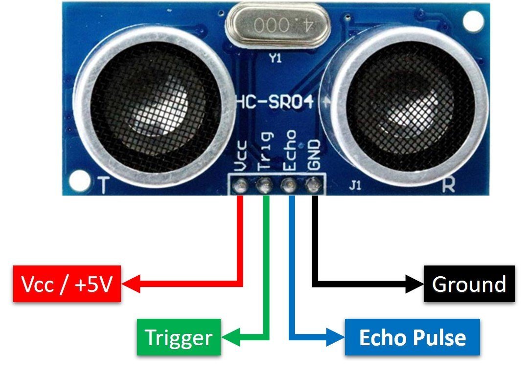
Vcc and Ground are used to power sensor. We should supply 5 volts to the Vcc pin and connect the GND pin with the ground terminal of the power supply.
Trigger: It is an input pin. A trigger pin is used to initiate the ultrasonic sensor to start distance measurement or distance ranging. When users want to get distance measurements from the sensor, we apply a 10µs pulse to this pin.
Echo: This is a pulse output pin. The echo pin produces a pulse as an output. The width of pulse or on-time of the pulse depends on the distance between the ultrasonic sensor and the obstacle which is placed in front of the HC-SR04 sensor. In idle conditions, this pin remains at an active low level.
Further details on ultrasonic sensor working are provided in the next section.
How HC-SR04 Sensor Works?
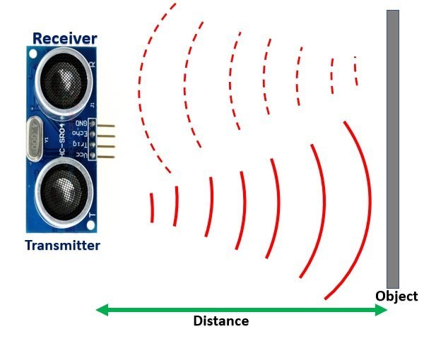
HC-SR04 ultrasonic sensor measures distance by using inaudible ultrasonic sound waves of 40KHz frequency. Like sound waves, ultrasonic waves travel through the air and if there is any obstacle in front of them, they reflect according to their angle of incidence. Moreover, if an object is placed parallel to an ultrasonic transmitter, ultrasonic waves reflect exactly at an angle of 180 degrees. Therefore, for distance measurement with HC-SR05 sensor, we place the object under test exactly in a parallel position with an ultrasonic sensor as shown in the figure below.
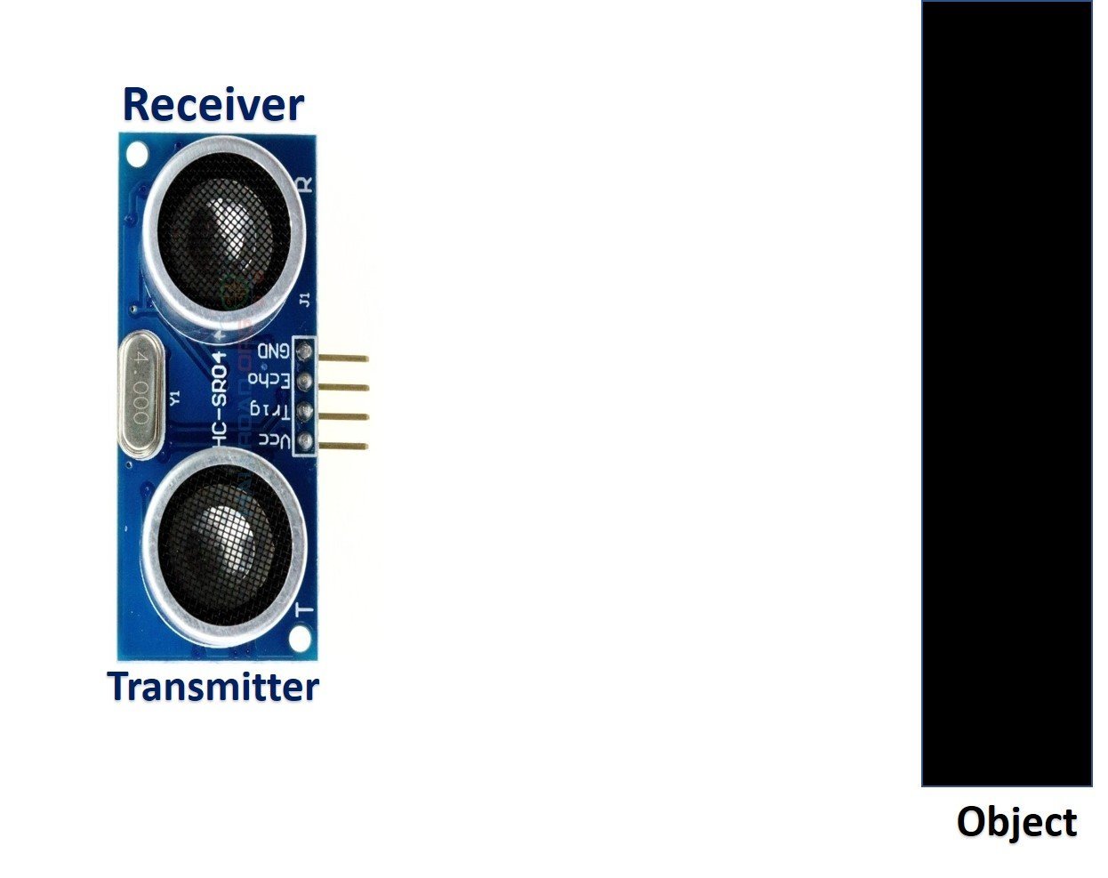
HC-SR05 ultrasonic sensor consists of two basic modules such as ultrasonic transmitter and ultrasonic receiver module. The transmitter circuit converts an electrical signal into a 40KHz burst of 8 sonar wave pulses. The input electrical signal to the transmitter circuit is 10µs pulse input to the trigger pin of the HC-SR04 sensor. As we mentioned earlier, we apply this trigger input signal through ESP32, ESP8266 NodeMCU or any microcontroller. On the other hand, the ultrasonic receiver circuit listens to these ultrasonic waves which are produced by the transmitter circuit.
Measure HC-SR04 Echo Pulse Time with ESP32/ESP8266 NodeMCU
- To start ranging with HC-SR04, first, we apply 10µs pulse to the trigger pin of the HC-SR04 sensor from the ESP32/ESP8266 NodeMCU digital output pin.
- As soon as 10µs input trigger signal becomes active low, the transmitter circuit produces a burst of 8 ultrasonic sonar pulses. At the same time, the Echo pin also makes a transition from a logic low level to a logic high level.
- When the Echo pin goes high, We start to measure time with the ESP32/ESP8266 NodeMCU duration measurement function.
- These waves travel through the air and if there is any object placed in parallel to the sensor, these waves reflect back after a collision with the object.
- As soon as the ultrasonic waves received by the receiver circuit after striking with an object, the echo pin goes low. ESP32/ESP8266 NodeMCU detects this transition of echo output signal from active high to an active low level and stops the measurement.
In short, by measuring the on-time of the Echo output pulse signal, we can measure the distance. The following figure illustrates the echo output signal with respect input trigger signal and 8 sonar pulses.
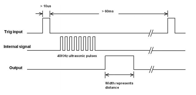
The duration for which the echo output signal remains high depends on the distance between the ultrasonic sensor and the object which we place in front of the sensor. Higher is the distance, the higher the time sonar waves will take to reach back to the ultrasonic receiver circuit. Because ultrasonic waves travel through the air with the speed of sound and speed remains constant.
How to Convert Time Duration into Distance
In the next section, we will see how to measure pulse duration using ESP32/ESP8266 NodeMCU. Let’s assume that we have measured the output pulse on time (t) with ESP32/ESP8266 NodeMCU. Now the question is how to convert this measured time into distance.
Well, this is the most obvious part of this tutorial. In high school, we all study a well-known distance-time equation that is S = vt. We can convert the pulse duration (t) into the distance (S) using this equation.
Distance (S) = Speed (v) * t //distance in meters
Here v is the speed of ultrasonic waves in air. The speed of ultrasonic waves in air is equal to the speed of sound which is 340 m/s (meter per second).
The above equation will give distance output in units of meter. But, if you want the distance in centimeter units, multiply 340 with 100. Hence, the above equation becomes:
S = 34000 * t // distance in cm
The time given in the above formula should also be divided by two. Because ultrasonic waves travel from the transmitter to the obstacle and then reflect back to the receiver circuit by traveling the same distance. We want to find the distance between HC-SR04 and the object only. Therefore, the formula to calculate distance becomes :
S = 17000 * t // distance in cm
Note: You don’t need to worry about these calculations as we will be using the MicroPython library for the HC-SR04 ultrasonic sensor to take distance measurements.
How to Interface HC-SR04 Ultrasonic sensor with ESP32 and ESP8266 NodeMCU
Until now we have seen the working of the ultrasonic sensor and the pin details. Now we know that to interface an HC-SR04 sensor with ESP32 and ESP8266, we need four pins out of which two are power supply pins and two are digital input output pins. One GPIO pin of the ESP32 and ESP8266 will be used as a digital output pin to provide a trigger signal to the ultrasonic sensor. Similarly, one GPIO pin will be used as a digital input pin to capture echo output signal of output sensor.
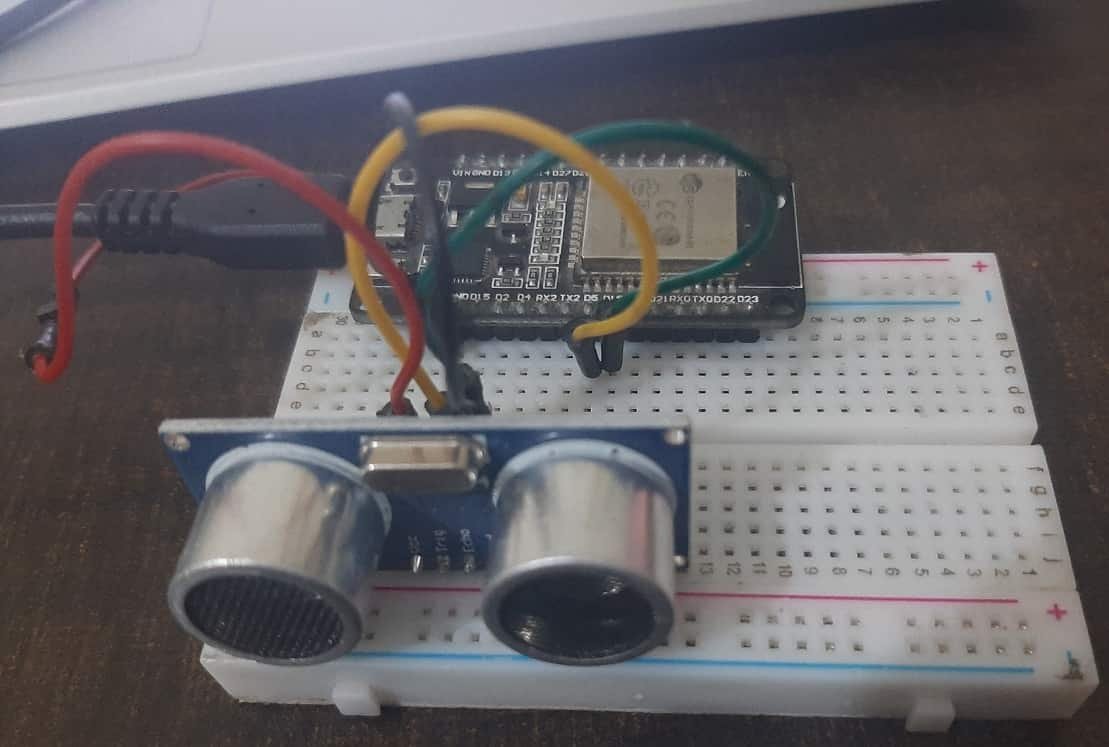
Now make the connection of the ESP32 and ESP8266 with the HC-SR04 sensor according to this connection diagram.
| HC-SR04 | ESP32 |
|---|---|
| Vcc | Vin |
| GND | GND |
| Trigger | GPIO5 |
| Echo | GPIO18 |
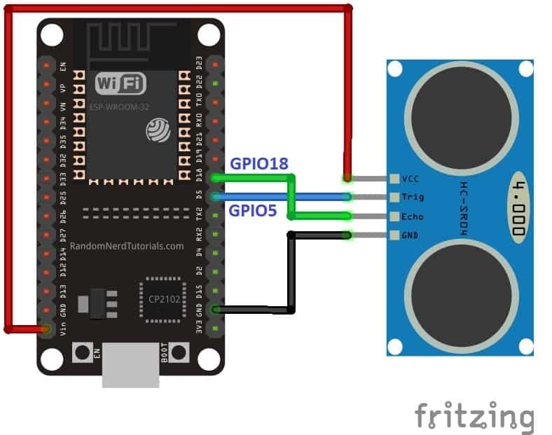
| HC-SR04 | ESP8266 NodeMCU |
|---|---|
| Vcc | Vin |
| GND | GND |
| Trigger | GPIO12 / D6 |
| Echo | GPIO14 / D5 |
HC-SR04 MicroPython Library
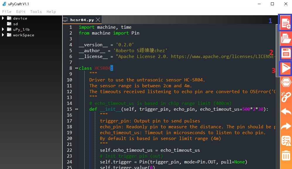
By default, MicroPython does not have an implementation of the HC-SR04 sensor. But, MicroPyhon provides I2C API of ESP32 and ESP8266 which can be used to read values from the HC-SR04 sensor. Fortunately, there is one library available which is developed by Adafruit and can be downloaded from this link. Download the following library and upload it to ESP32/ESP8266 board with the name of hcsr04.py using uPyCraft or Thonny IDE.
import machine, time
from machine import Pin

__version__ = '0.2.0'
__author__ = 'Roberto S阠嶖端chez'
__license__ = "Apache License 2.0. https://www.apache.org/licenses/LICENSE-2.0"

class HCSR04:
    """
    Driver to use the untrasonic sensor HC-SR04.
    The sensor range is between 2cm and 4m.
    The timeouts received listening to echo pin are converted to OSError('Out of range')
    """
    # echo_timeout_us is based in chip range limit (400cm)
    def __init__(self, trigger_pin, echo_pin, echo_timeout_us=500*2*30):
        """
        trigger_pin: Output pin to send pulses
        echo_pin: Readonly pin to measure the distance. The pin should be protected with 1k resistor
        echo_timeout_us: Timeout in microseconds to listen to echo pin.
        By default is based in sensor limit range (4m)
        """
        self.echo_timeout_us = echo_timeout_us
        # Init trigger pin (out)
        self.trigger = Pin(trigger_pin, mode=Pin.OUT, pull=None)
        self.trigger.value(0)

        # Init echo pin (in)
        self.echo = Pin(echo_pin, mode=Pin.IN, pull=None)

    def _send_pulse_and_wait(self):
        """
        Send the pulse to trigger and listen on echo pin.
        We use the method `machine.time_pulse_us()` to get the microseconds until the echo is received.
        """
        self.trigger.value(0) # Stabilize the sensor
        time.sleep_us(5)
        self.trigger.value(1)
        # Send a 10us pulse.
        time.sleep_us(10)
        self.trigger.value(0)
        try:
            pulse_time = machine.time_pulse_us(self.echo, 1, self.echo_timeout_us)
            return pulse_time
        except OSError as ex:
            if ex.args[0] == 110: # 110 = ETIMEDOUT
                raise OSError('Out of range')
            raise ex

    def distance_mm(self):
        """
        Get the distance in milimeters without floating point operations.
        """
        pulse_time = self._send_pulse_and_wait()

        # To calculate the distance we get the pulse_time and divide it by 2
        # (the pulse walk the distance twice) and by 29.1 becasue
        # the sound speed on air (343.2 m/s), that It's equivalent to
        # 0.34320 mm/us that is 1mm each 2.91us
        # pulse_time // 2 // 2.91 -> pulse_time // 5.82 -> pulse_time * 100 // 582
        mm = pulse_time * 100 // 582
        return mm

    def distance_cm(self):
        """
        Get the distance in centimeters with floating point operations.
        It returns a float
        """
        pulse_time = self._send_pulse_and_wait()

        # To calculate the distance we get the pulse_time and divide it by 2
        # (the pulse walk the distance twice) and by 29.1 becasue
        # the sound speed on air (343.2 m/s), that It's equivalent to
        # 0.034320 cm/us that is 1cm each 29.1us
        cms = (pulse_time / 2) / 29.1
        return cms
Uploading HC-SR04 Library with uPyCraft IDE
Now, we will look at how to upload the HC-SR04 MicroPython library to ESP32 and ESP8266. This step is required because MicroPython itself does not contain the sensor’s library. Follow the steps in order to successfully upload the library to ESP32/ESP8266 in uPyCraft IDE:
- First, in the Tools section, click on the NEW FILE button and open a file.

- Then replicate the above given microPython hc-sr04 library in that file.
- Name the file hcsr04.py and save it by choosing your desired directory.

- Now press the button DOWNLOAD AND RUN in the tools section.

As soon as you click on the download and run button, you will get the message that states “download ok”. Moreover, you will also see hcsr04.py file lists under the device menu.
You have now successfully uploaded the HC-SR04 library to ESP32/ESP8266 using uPyCraft IDE. After that, we can use the above library functions to take distance measurements. You can use a similar procedure to upload files using Thonny IDE.
Uploading HC-SR04 Library in Thonny IDE
If you are using Thonny IDE, open a new file and copy the code as we did in uPyCraft IDE.
- Save the file as hcsr04.py
- In addition, head over to Device> Upload Current Script with Current Name
In the latest version of Thonny IDE, you will get the option to save the library to a device when you click on the save as option.
You have successfully uploaded HC-SR04 library to ESP32/ESP8266 using Thonny IDE.
MicroPython HC-SR04 Ultrasonic Sensor Code
As we have already uploaded the HC-SR04 library to ESP32/ESP8266 boards. Now we can use the functions available in the HC-SR04 library to get sensor readings.
HC-SR04 MicroPython Example
Now let’s look at the MicroPython script for HC-SR04 to get distance readings. Copy the following code to the main.py file and upload the main.py file to ESP32/ESP8266 by following the same process we followed to upload the library file. This microPython script reads distance from the HC-SR04 sensor and prints it on the MicroPython shell console.
from hcsr04 import HCSR04
from time import sleep

# hc-sr05 pins for ESP32
sensor = HCSR04(trigger_pin=5, echo_pin=18, echo_timeout_us=10000)

# hc-sr05 pins for ESP8266
#sensor = HCSR04(trigger_pin=12, echo_pin=14, echo_timeout_us=10000)

while True:
    distance = sensor.distance_cm()
    print('Distance:', distance, 'cm')
    sleep(1)
How the Code Works?
Importing Libraries
Firstly, we import hcsr04 and sleep module so that we will be able to access it methods through its defined classes.
from hcsr04 import HCSR04
from time import sleep
Defining ESP32/ESP8266 GPIO Pins for HC-SR04
Now, we initialize the gpio pins of ESP32 and ESP8266 for the HC-SR04 sensor. The first argument specifies the GPIO pin for trigger pin. This is given as GPIO5 for ESP32 and GPIO12 for ESP8266. The second parameter specifies the GPIO pin for the echo pin. This is given as GPIO18 for ESP32 and GPIO14 for ESP8266. The last argument is the maximum travel time of the sound wave.
HC-SR04 creates an object of the HCSR04() method from hcsr04 class with the name of “sensor”.
# hc-sr05 pins for ESP32
sensor = HCSR04(trigger_pin=5, echo_pin=18, echo_timeout_us=10000)

# hc-sr05 pins for ESP8266
#sensor = HCSR04(trigger_pin=12, echo_pin=14, echo_timeout_us=10000)
Getting HC-SR04 Sensor Values
Inside the while loop, get the sensor reading by using an object “sensor” on distance_cm() ad save the value in the distance variable.
distance = sensor.distance_cm()After that print the distance values on the micropython shell console after every one second.
print('Distance:', distance, 'cm')
    sleep(1)
Demo
To test the MicroPython script for HC-SR04 with ESP32 and ESP8266, upload the main.py file to ESP32/ESP8266. After uploading the MicroPython script, click on Enable/Reset button of ESP32 or ESP8266:


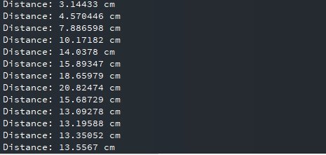
You will see the distance value getting printed on shell console after every one second as follows:
MicroPython: Displaying HC-SR04 Sensor values on OLED Display
In this section, we will see how to display measured distance reading on a 0.96 SSD1306 OLED display using MicroPython and ESP32/ESP8266.
SSD1306 OLED Display MicroPython Library
We have already uploaded the HC-SR04 MicroPython library to ESP32 and ESP8266 NodeMCU. For an OLED display, we will also need to upload OLED microPython library to ESP boards.
Copy the following code which is a MicroPython library of OLED and upload the library using either uPycraft or Thonny IDE by giving it a name of ssd1306.py. You should follow the same procedure to upload the library as we did for hcsr04.py.
# MicroPython SSD1306 OLED driver, I2C and SPI interfaces
from micropython import const
import time
import framebuf
import sys

currentBoard=""
if(sys.platform=="esp8266"):
  currentBoard="esp8266"
elif(sys.platform=="esp32"):
  currentBoard="esp32"
elif(sys.platform=="pyboard"):
  currentBoard="pyboard"
  import pyb
# register definitions
SET_CONTRAST        = const(0x81)
SET_ENTIRE_ON       = const(0xa4)
SET_NORM_INV        = const(0xa6)
SET_DISP            = const(0xae)
SET_MEM_ADDR        = const(0x20)
SET_COL_ADDR        = const(0x21)
SET_PAGE_ADDR       = const(0x22)
SET_DISP_START_LINE = const(0x40)
SET_SEG_REMAP       = const(0xa0)
SET_MUX_RATIO       = const(0xa8)
SET_COM_OUT_DIR     = const(0xc0)
SET_DISP_OFFSET     = const(0xd3)
SET_COM_PIN_CFG     = const(0xda)
SET_DISP_CLK_DIV    = const(0xd5)
SET_PRECHARGE       = const(0xd9)
SET_VCOM_DESEL      = const(0xdb)
SET_CHARGE_PUMP     = const(0x8d)
class SSD1306:
  def __init__(self, width, height, external_vcc):
    self.width = width
    self.height = height
    self.external_vcc = external_vcc
    self.pages = self.height // 8
    self.buffer = bytearray(self.pages * self.width)
    self.framebuf = framebuf.FrameBuffer(self.buffer, self.width, self.height, framebuf.MVLSB)
    self.poweron()
    self.init_display()
  def init_display(self):
    for cmd in (
      SET_DISP | 0x00, # off
      # address setting
      SET_MEM_ADDR, 0x00, # horizontal
      # resolution and layout
      SET_DISP_START_LINE | 0x00,
      SET_SEG_REMAP | 0x01, # column addr 127 mapped to SEG0
      SET_MUX_RATIO, self.height - 1,
      SET_COM_OUT_DIR | 0x08, # scan from COM[N] to COM0
      SET_DISP_OFFSET, 0x00,
      SET_COM_PIN_CFG, 0x02 if self.height == 32 else 0x12,
      # timing and driving scheme
      SET_DISP_CLK_DIV, 0x80,
      SET_PRECHARGE, 0x22 if self.external_vcc else 0xf1,
      SET_VCOM_DESEL, 0x30, # 0.83*Vcc
      # display
      SET_CONTRAST, 0xff, # maximum
      SET_ENTIRE_ON, # output follows RAM contents
      SET_NORM_INV, # not inverted
      # charge pump
      SET_CHARGE_PUMP, 0x10 if self.external_vcc else 0x14,
      SET_DISP | 0x01): # on
      self.write_cmd(cmd)
    self.fill(0)
    self.show()
  def poweroff(self):
    self.write_cmd(SET_DISP | 0x00)
  def contrast(self, contrast):
    self.write_cmd(SET_CONTRAST)
    self.write_cmd(contrast)
  def invert(self, invert):
    self.write_cmd(SET_NORM_INV | (invert & 1))
  def show(self):
    x0 = 0
    x1 = self.width - 1
    if self.width == 64:
      # displays with width of 64 pixels are shifted by 32
      x0 += 32
      x1 += 32
    self.write_cmd(SET_COL_ADDR)
    self.write_cmd(x0)
    self.write_cmd(x1)
    self.write_cmd(SET_PAGE_ADDR)
    self.write_cmd(0)
    self.write_cmd(self.pages - 1)
    self.write_data(self.buffer)
  def fill(self, col):
    self.framebuf.fill(col)
  def pixel(self, x, y, col):
    self.framebuf.pixel(x, y, col)
  def scroll(self, dx, dy):
    self.framebuf.scroll(dx, dy)
  def text(self, string, x, y, col=1):
    self.framebuf.text(string, x, y, col)
  def hline(self, x, y, w, col):
    self.framebuf.hline(x, y, w, col)
  def vline(self, x, y, h, col):
    self.framebuf.vline(x, y, h, col)
  def line(self, x1, y1, x2, y2, col):
    self.framebuf.line(x1, y1, x2, y2, col)
  def rect(self, x, y, w, h, col):
    self.framebuf.rect(x, y, w, h, col)
  def fill_rect(self, x, y, w, h, col):
    self.framebuf.fill_rect(x, y, w, h, col)
  def blit(self, fbuf, x, y):
    self.framebuf.blit(fbuf, x, y)

class SSD1306_I2C(SSD1306):
  def __init__(self, width, height, i2c, addr=0x3c, external_vcc=False):
    self.i2c = i2c
    self.addr = addr
    self.temp = bytearray(2)
    super().__init__(width, height, external_vcc)
  def write_cmd(self, cmd):
    self.temp[0] = 0x80 # Co=1, D/C#=0
    self.temp[1] = cmd
    #IF SYS  :
    global currentBoard
    if currentBoard=="esp8266" or currentBoard=="esp32":
      self.i2c.writeto(self.addr, self.temp)
    elif currentBoard=="pyboard":
      self.i2c.send(self.temp,self.addr)
    #ELSE:

  def write_data(self, buf):
    self.temp[0] = self.addr << 1
    self.temp[1] = 0x40 # Co=0, D/C#=1
    global currentBoard
    if currentBoard=="esp8266" or currentBoard=="esp32":
      self.i2c.start()
      self.i2c.write(self.temp)
      self.i2c.write(buf)
      self.i2c.stop()
    elif currentBoard=="pyboard":
      #self.i2c.send(self.temp,self.addr)
      #self.i2c.send(buf,self.addr)
      self.i2c.mem_write(buf,self.addr,0x40)
  def poweron(self):
    pass

class SSD1306_SPI(SSD1306):
  def __init__(self, width, height, spi, dc, res, cs, external_vcc=False):
    self.rate = 10 * 1024 * 1024
    dc.init(dc.OUT, value=0)
    res.init(res.OUT, value=0)
    cs.init(cs.OUT, value=1)
    self.spi = spi
    self.dc = dc
    self.res = res
    self.cs = cs
    super().__init__(width, height, external_vcc)
  def write_cmd(self, cmd):
    global currentBoard
    if currentBoard=="esp8266" or currentBoard=="esp32":
      self.spi.init(baudrate=self.rate, polarity=0, phase=0)
    elif currentBoard=="pyboard":
      self.spi.init(mode = pyb.SPI.MASTER,baudrate=self.rate, polarity=0, phase=0)
    self.cs.high()
    self.dc.low()
    self.cs.low()
    global currentBoard
    if currentBoard=="esp8266" or currentBoard=="esp32":
      self.spi.write(bytearray([cmd]))
    elif currentBoard=="pyboard":
      self.spi.send(bytearray([cmd]))
    self.cs.high()
  def write_data(self, buf):
    global currentBoard
    if currentBoard=="esp8266" or currentBoard=="esp32":
      self.spi.init(baudrate=self.rate, polarity=0, phase=0)
    elif currentBoard=="pyboard":
      self.spi.init(mode = pyb.SPI.MASTER,baudrate=self.rate, polarity=0, phase=0)
    self.cs.high()
    self.dc.high()
    self.cs.low()
    global currentBoard
    if currentBoard=="esp8266" or currentBoard=="esp32":
      self.spi.write(buf)
    elif currentBoard=="pyboard":
      self.spi.send(buf)
    self.cs.high()
  def poweron(self):
    self.res.high()
    time.sleep_ms(1)
    self.res.low()
    time.sleep_ms(10)
    self.res.high()
Schematic – OLED with ESP32/ESP8266 and HC-SR04 Ultrasonic Sensor
To interface ESP32 and ESP8266 with OLED, we use I2C pins of ESP8266 and ESP32. Let’s first see the I2C for both boards.
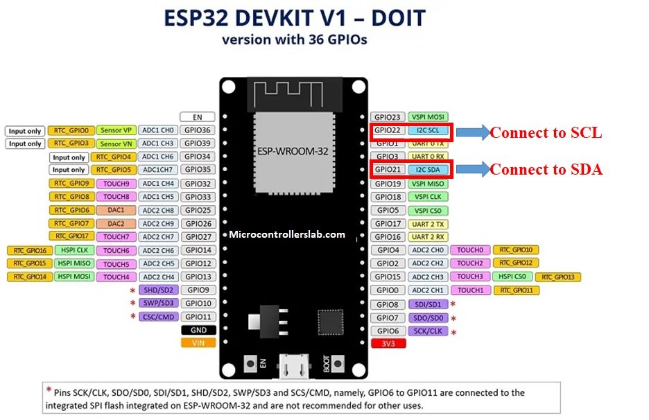
ESP32 I2C Pins
The I2C pins stated above are set in default. If we want to change the GPIO pins we have to set them in code. The diagram below shows the pinout for the ESP32.
ESP8266 NodeMCU I2C Pins
The I2C pins stated above are set in default. If we want to change the GPIO pins we have to set them in code. The diagram below shows the pinout for the ESP8266 NodeMCU.
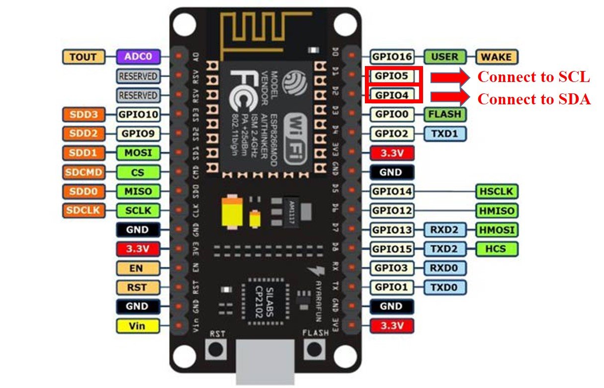
Note: If we use other GPIO pins of ESP32 and ESP8266 for I2C communication, we can define other pins inside the MicroPython script. We don’t have to use default I2C pins.
You can learn more about I2C communication here:
Schematic Diagrams
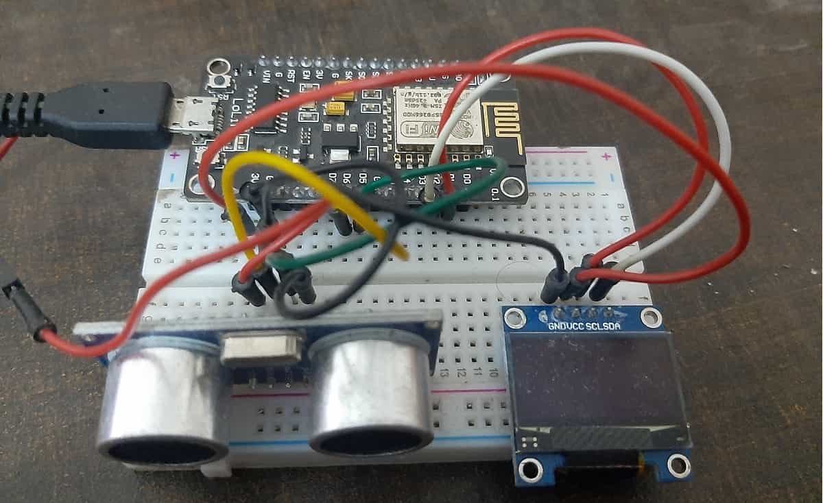
Assemble the circuit as shown in the schematic diagram below:
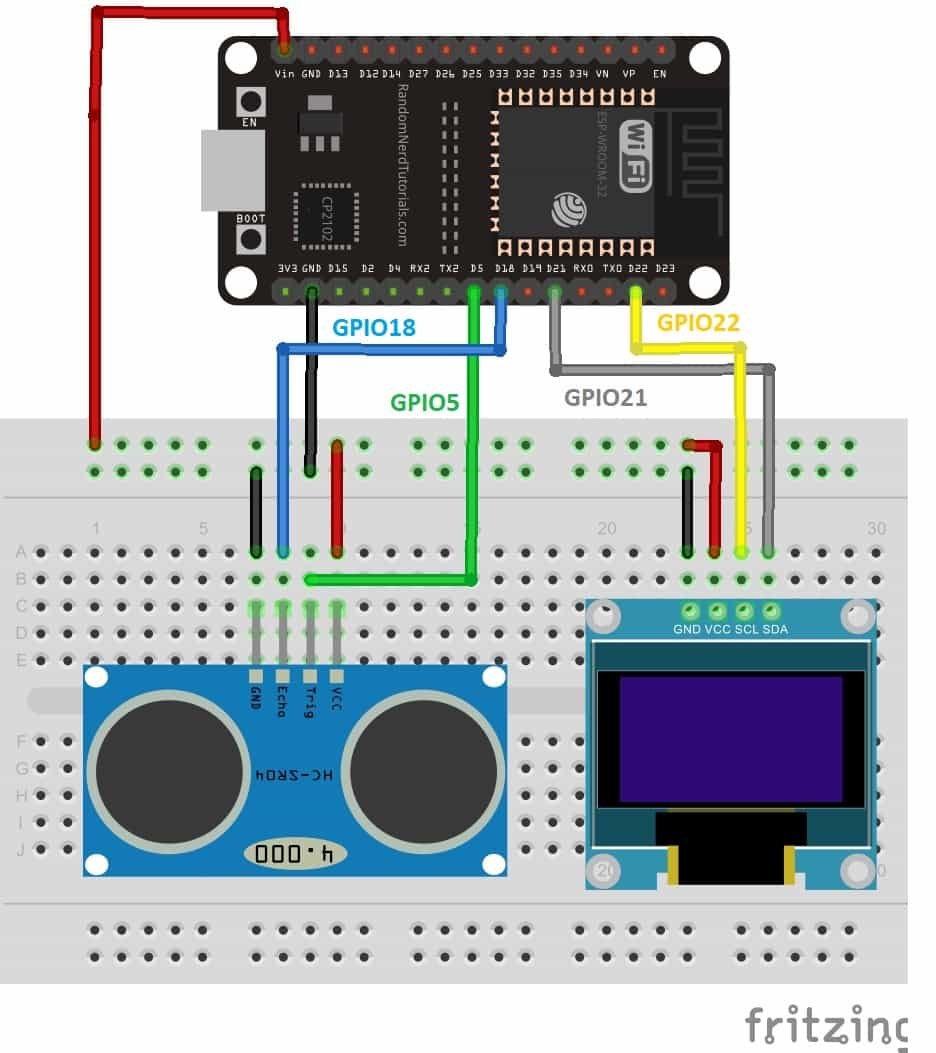
As you can see above, we have connected all the VCC terminals of OLED and HC-SR04 with a Vin pin of ESP32. The data trigger and echo pins of the ultrasonic sensor are connected with the GPIO5 and GPIO18 pins of ESP32 board, respectively.
The SCL terminal of the OLED is connected with GPIO22 and the SDA terminal of the OLED is connected with the GPIO21 pin of ESP32. The grounds of all three devices are common.
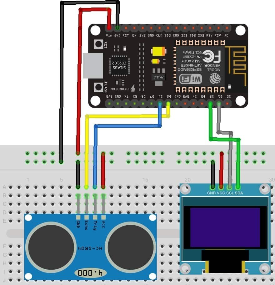
As you can see above, we have connected all the VCC terminals of OLED and HC-SR04 with a Vin pin of ESP8266 NodeMCU. The data trigger and echo pins of the ultrasonic sensor are connected with the GPIO12 and GPIO14 pins of ESP8266 NodeMCU board, respectively.
The SCL terminal of the OLED is connected with GPIO22 and the SDA terminal of the OLED is connected with the GPIO21 pin of ESP8266 NodeMCU. The grounds of all three devices are common.
Assemble the circuit as shown in the schematic diagram below:
| ESP8266 NodeMCU | SSD1306 OLED Display | HC-SR04 |
|---|---|---|
| Vin | VCC | VCC |
| GPIO5/D1 | SCK | |
| GPIO4/D2 | SDA | |
| GPIO12/D6 | Trigger | |
| GPIO14/D5 | Echo | |
| GND | GND | GND |
| ESP32 board | SSD1306 OLED Display | HC-SR04 |
|---|---|---|
| Vin | VCC | VCC |
| GPIO21(I2C SDA) | SDA | |
| GPIO22(I2C SCL) | SCL | |
| GPIO5 | Trigger | |
| GPIO18 | Echo | |
| GND | GND | GND |
Upload these three files to ESP32 and ESP8266 using uPyCraft IDE or thonny IDE:
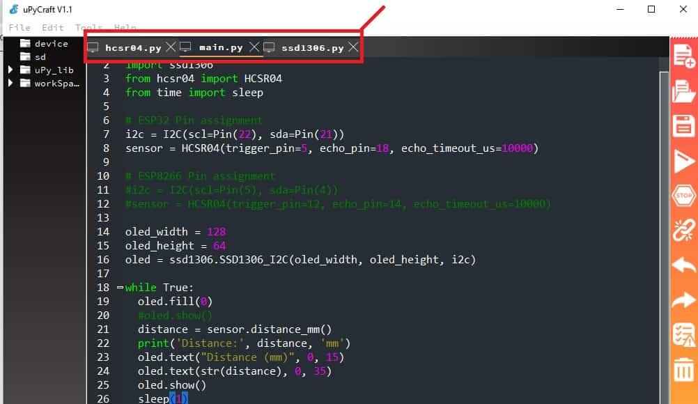
- hcsr04.py
- ssd1306.py
- main.py
main.py MicroPython Script
from machine import Pin, I2C
import ssd1306
from hcsr04 import HCSR04
from time import sleep

# ESP32 Pins for hcsr04
i2c = I2C(scl=Pin(22), sda=Pin(21))
sensor = HCSR04(trigger_pin=5, echo_pin=18, echo_timeout_us=10000)

# ESP8266 Pins for hcsr04
#i2c = I2C(scl=Pin(5), sda=Pin(4))
#sensor = HCSR04(trigger_pin=12, echo_pin=14, echo_timeout_us=10000)

oled_width = 128
oled_height = 64
oled = ssd1306.SSD1306_I2C(oled_width, oled_height, i2c)

while True:
  oled.fill(0)
  #oled.show()
  distance = sensor.distance_mm()
  print('Distance:', distance, 'mm')
  oled.text("Distance (mm)", 0, 15)
  oled.text(str(distance), 0, 35)
  oled.show()
  sleep(1)
This MicroPython is similar to the one that we discussed in the last section except for the OLED part. You can learn about OLED interfacing with ESP32 and ESP8266 using MiroPython here:
How Does the Code Work?
In the section, we only explained the Micropython code part which is used to display HC-SR04 sensor values on OLED. Because reset of the code is the same as we have used in previous sections to display sensor readings on the shell console.
Import SSD1306 OLED library.
import ssd1306Create an instance of the SSD1306_I2C() method by giving it the name of “oled”. The first two arguments to SSD1306_I2C() are the size of OLED that is the number of columns and rows. A last argument is an object of I2C pins which we define with SoftI2C().
oled_width = 128
oled_height = 64
oled = ssd1306.SSD1306_I2C(oled_width, oled_height, i2c)
Clears the OLED display with led.fill() routine.
oled.fill(0)Finally, display the text along with distance reading on OLED.
oled.text("Distance (mm)", 0, 15)
oled.text(str(distance), 0, 35)
oled.show()
In the end, call the show() method on the oled method for changes to show on OLED.
lcd.show() #display pixDemonstration
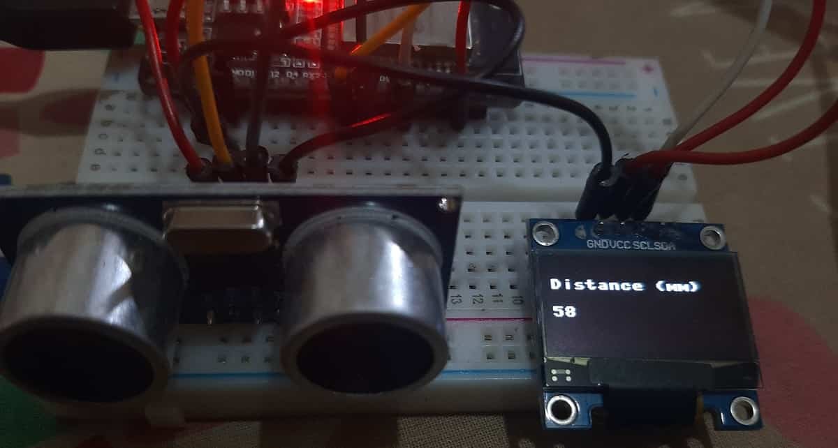
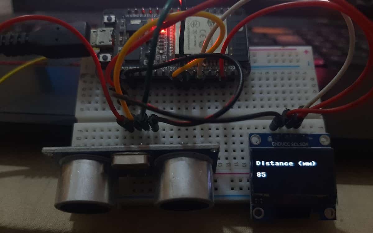
Upload the above code as main.py file along with hcsr04.py and ssd1306.py to ESP32 or ESP8266. After that press the reset button on your ESP board. You will get HC-SR04 readings on the OLED display as follows:
We have other guides with popular sensors:
- IoT based Contactless Water level Monitoring with ESP32 and HC-SR04
- MPU-6050 with ESP32/ESP8266 (Accelerometer, Gyroscope, and temperature)
- MicroPython: BME680 with ESP32 and ESP8266 (Gas, Pressure, Temperature, Humidity)
- ESP32/ESP8266: Send Sensor Readings via Email (IFTTT)
- BME280 with ESP32 and ESP8266 – Measure Temperature, Humidity, and Pressure
- BME280 Web Server with ESP32/ESP8266 (Weather Station)
- MicroPython: DS18B20 Web Server with ESP32/ESP8266(Weather Station)
- MicroPython: DHT11/DHT22 Web Server with ESP32/ESP8266 (Weather Station)