In this user guide, we will learn how to send sensor readings in our email through ESP32 and ESP8266 development board using MicroPython and IFTTT services. We will transmit the BME280 sensors readings such as temperature, humidity through email notification. To send email notifications, we will use IFTTT a third-party service. In short, you will send any sensor reading with email notification and make HTTP POST requests using ESP32 or ESP8266 and MicroPython.

Recommended Components
The following components are used in this project or are helpful for getting started with MicroPython on ESP32 and ESP8266.
| Component | How it’s used in this project | Buy on Amazon |
|---|---|---|
| ESP32 Development Board (DevKit V1) | The ESP32 board flashed with MicroPython firmware. | Check Price |
| ESP8266 NodeMCU (ESP-12E) | The ESP8266 NodeMCU running the same MicroPython code. | Check Price |
| Micro USB Cable | Programs and powers the board from your PC. | Check Price |
| BME280 Sensor | Provides the temperature and humidity readings emailed via IFTTT. | Check Price |
| Breadboard | Holds the sensor and board for wiring. | Check Price |
| Jumper Wires | Connect the sensor to the I2C pins. | Check Price |
As an Amazon Associate we earn from qualifying purchases. Prices and availability are accurate as of the date/time indicated and are subject to change.
You can also read our previously published BME280 with MicroPython Articles:
Prerequisites
Before we start this lesson make sure you are familiar with and have the latest version of MicroPython firmware installed in your ESP boards and have a running Integrated Development Environment (IDE) in which we will be doing the programming such as uPyCraft IDE or Thonny IDE.
- Getting Started with uPyCraft IDE on ESP32 and ESP8266
- Getting Started with Thonny MicroPython IDE for ESP32 and ESP8266
You should also know how to connected ESP32/ESP8266 boards with WiFi networking using network library of MicroPython. If you don’t know, you can read these getting started guides:
This article is divided into these sub-topics:
- Introduction of BME280 Sensor Module
- Introduction of IFTTT
- Setting up and testing IFTTT
- Simple project using BME280 sensor, IFTTT, and ESP32/8266 to send sensor readings to our email
Project Overview

Our project starts with our ESP32/ESP8266 booting. The BME280 sensor will be connected to the ESP board through the I2C GPIO pins which we will specify later. When the development board boots, the ESP32/ESP8266 sensor gets particular readings of temperature, pressure, and humidity from BME280. This acts as a trigger that causes the HTTP post request to be sent to the IFTTT service which causes the sensor readings to be transferred as an email notification message in our email account. This is a brief description of our project. We will now explain each component comprehensively.
Introduction of IFTTT – Email Notificaton Service
IFTTT means ‘If this, then that.’ It is an open-source service that gives the user the freedom to program a response to an event according to their likes. We can create an applet which are chains of conditional statements by a combination of several app services and add triggering parameters. For our project, we will be using this service, whenever the ESP board makes a request and hence send the sensor readings to our email. To work with this web service we will have to follow a series of steps to ensure the proper functionality.
Creating an IFTTT Account
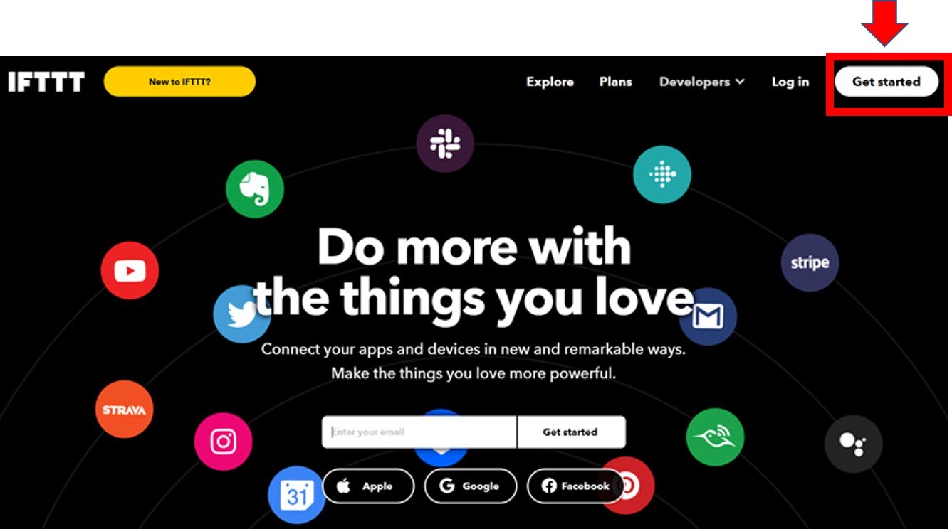
Although the IFTTT service is free to use, we will have to create an account. First go to the following website: https://ifttt.com/
(1) The following window will appear. Click on the ‘Get Started’ button.
(2) The following window will appear. You can select any one of these three options (Apple, Google, or Facebook) to connect or you can simply ‘sign up’ with your own email address. We will be following this scheme.
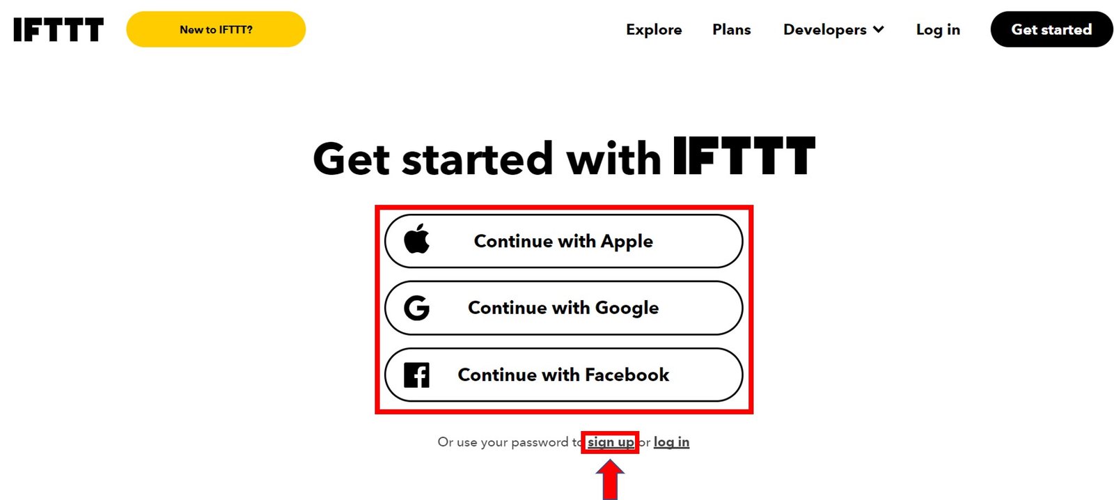
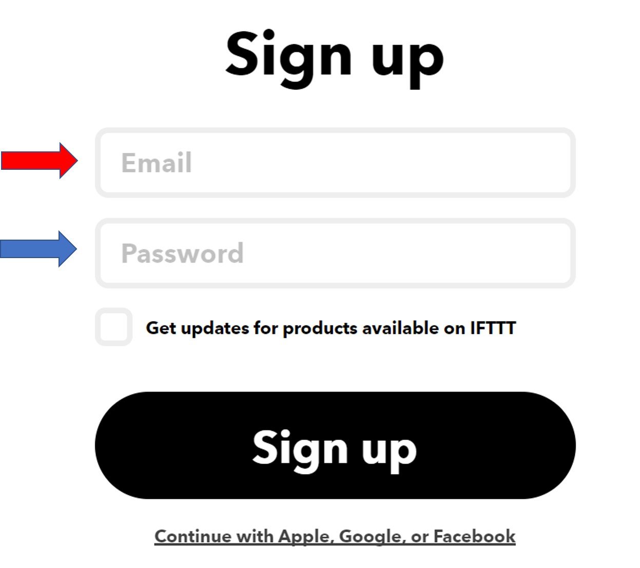
(3) Click the ‘sign up’ tag. You will see the following window pop up. Enter your email address and password to start working in IFTTT. This whole process is free of cost for the first three applets.
Creating an Applet
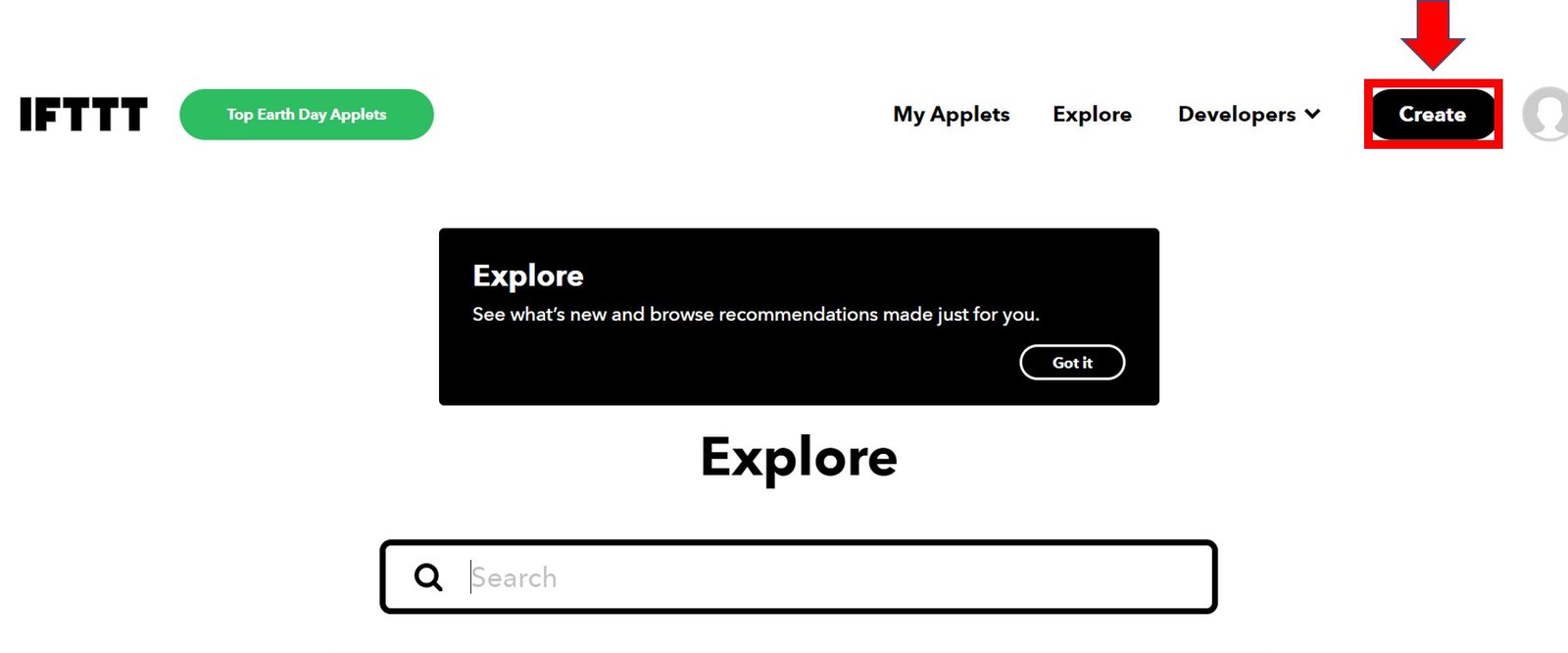
(1) After you have created your account, we will be directed to the page where we will create our IFTTT applet. Click on ‘Create.’
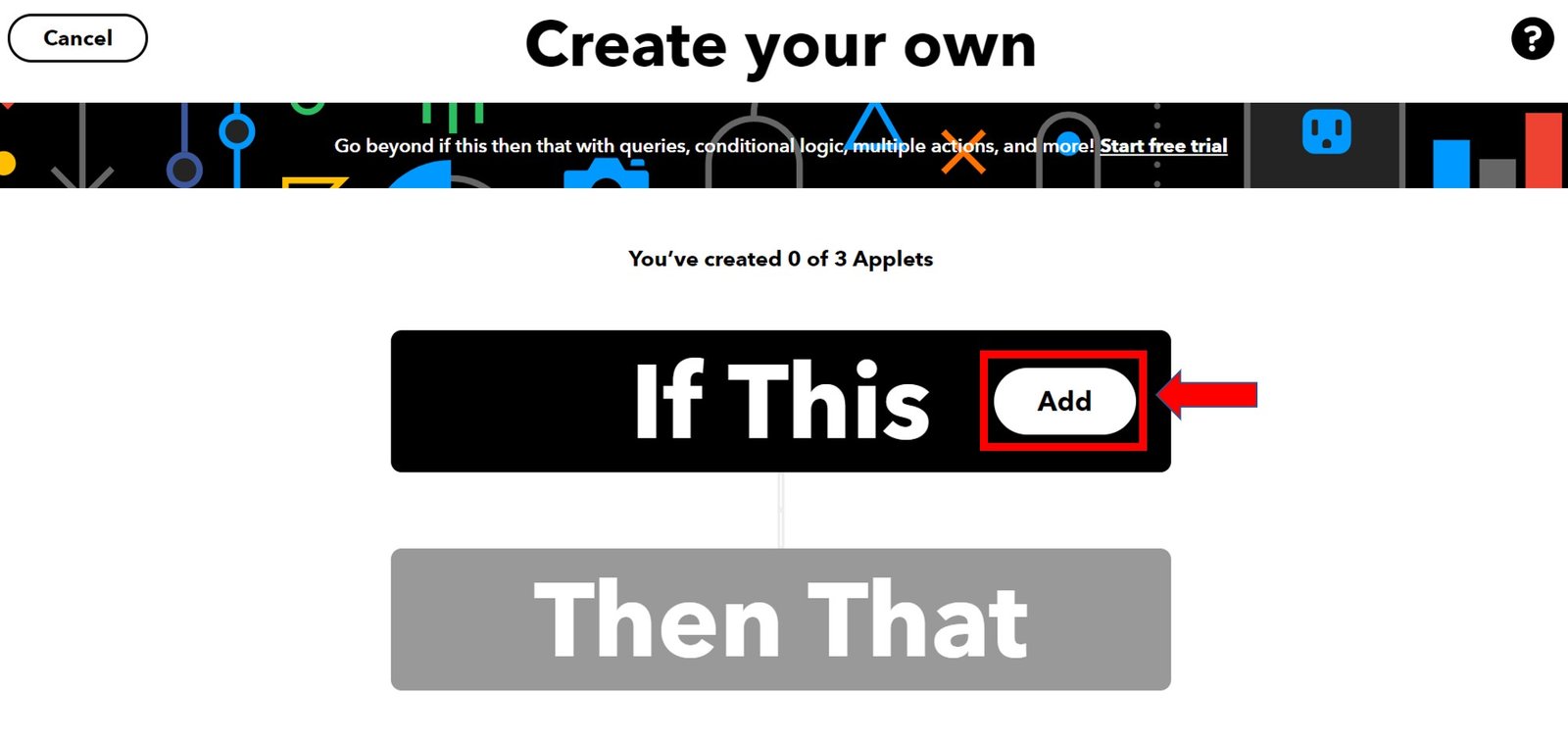
(2) The following window opens up. Select the following Add button in the ‘If This’ section.
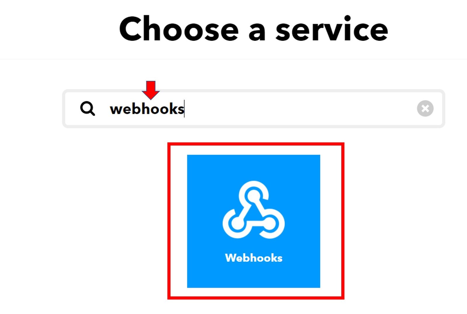
(3) Another page will open in which we will have to choose our service. There is a lot of options to choose from. Write down ‘webhooks’ in the search option and its icon will appear:
(4) Next, choose the trigger as: ‘Receive a web request’ by clicking on it. Whenever webhooks will receive a web request for this trigger, some action will take place. This, we will define in the ‘THAT’ section of the IFTTT applet.
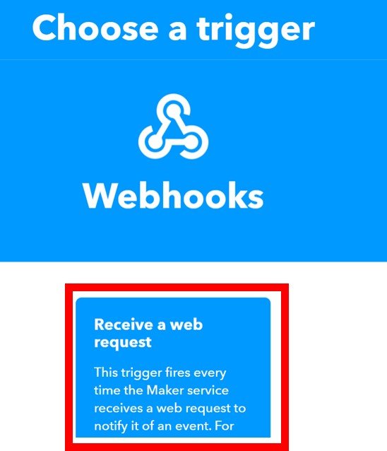
After clicking the Receive a web request, the following window will appear. Write down BME280 as the event name for the web request. Click the ‘Create Trigger’ button. You can give any user-readable name to this trigger event.

Create Gmail Email Notification Service
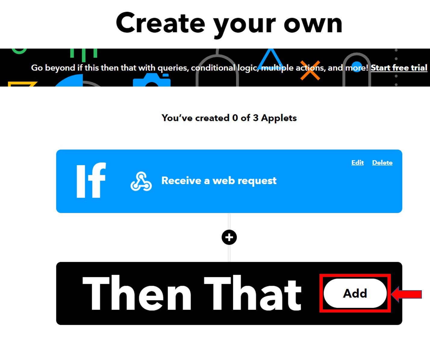
(1) After the trigger is created, we are taken back to the web page where we first added the service for the ‘IF THIS’ section. Now we will click the ADD button for the ‘THEN THAT’ section.
(2) Now, we will choose the service. We have to choose what will happen if a web request is received. Thus, we will type ‘gmail’ in the search option and click on its icon. This is because we want to send an email whenever an HTTP Post request is received from ESP32/ESP8266 which we have set to the BME280 sensor in previous steps.

(3) The following window opens up where we have to choose whether to send the email to different recipients (up to 20) or ourselves. We will click on ‘Send an email.’

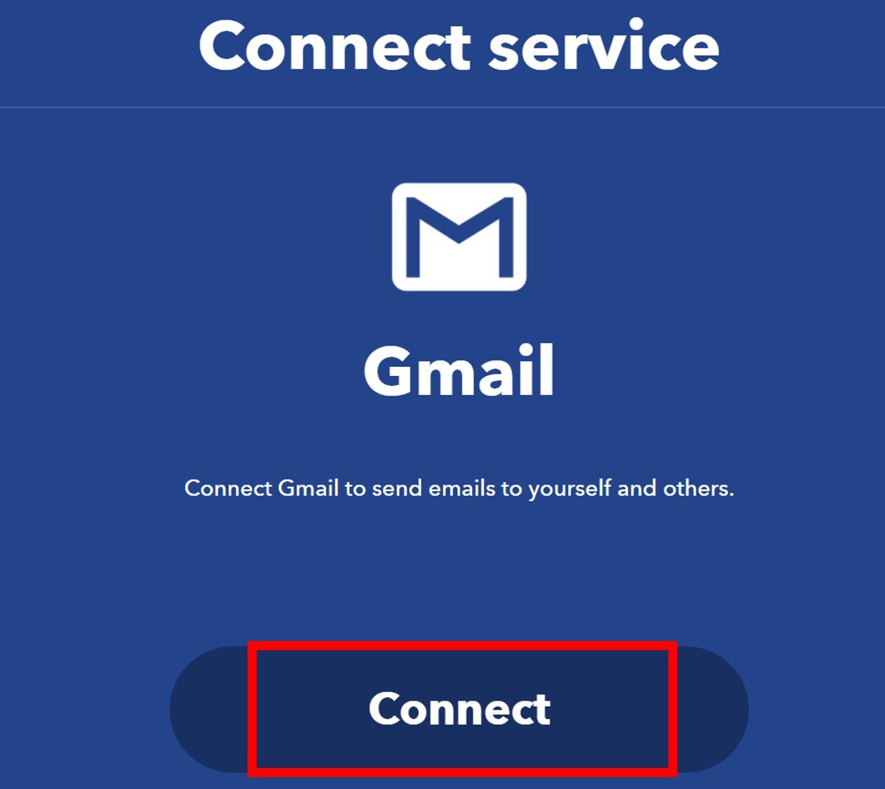
(4) Click on the ‘Connect’ button as shown below.
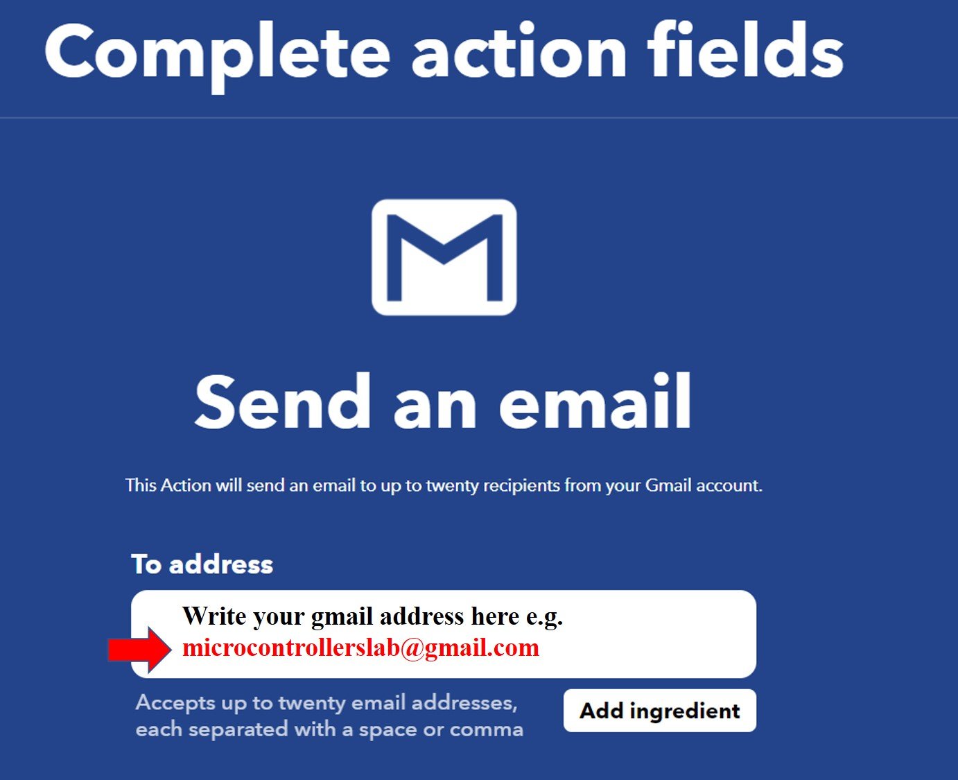
(5) Next, we will complete all the details. Write down your gmail address in the ‘To address’ tab, as shown below:
(6) Fill in all the entries to create the subject and body of your email notification. Afterward, select the ‘Create Action’ button.
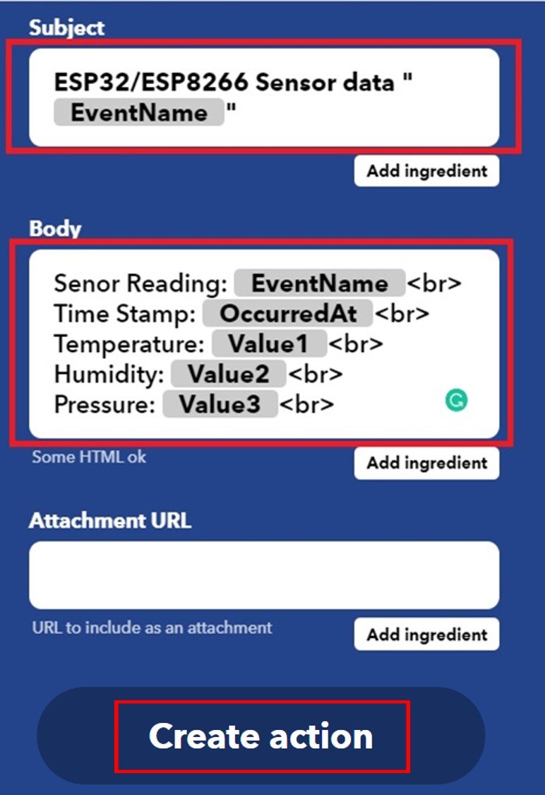
Senor Reading: {{EventName}}
Time Stamp: {{OccurredAt}}
Temperature: {{Value1}}
Humidity: {{Value2}}
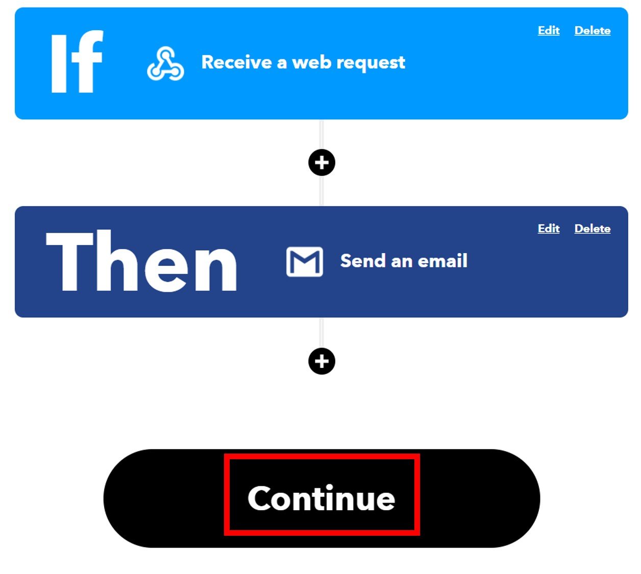
Pressure: {{Value3}}(7) After we have created the action, we will be guided towards the initial web page of IFTTT. Click ‘Continue’ to proceed.
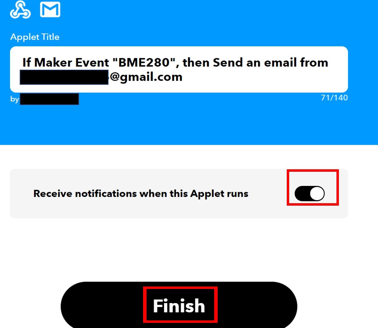
(8) After this click the Finish button. Make sure to turn ON the notifications when the applet is running.
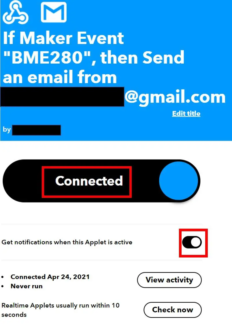
(9) You have successfully created the applet. Make sure to turn on the notifications whenever the applet becomes active.
Testing Your IFTTT Applet
Before we proceed further with our project, let us first test our applet.
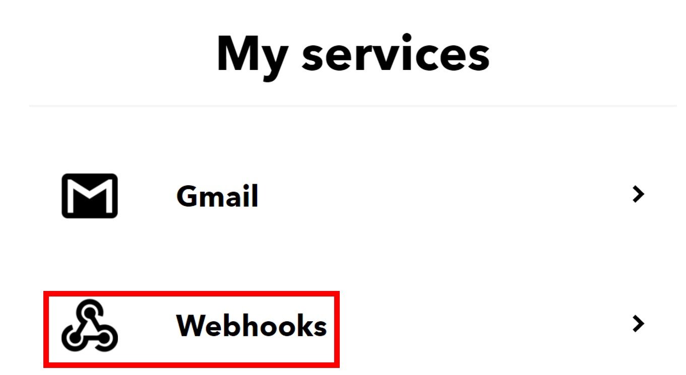
(1) Go to your and select “My Servies” or Open a webpage with the link: ifttt.com/my_services. The following windows will appear. Afterward, click on Webhooks
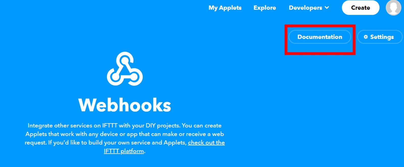
(2) This will take you to the following web page. Click on ‘Documentation.’
(3) You will receive a key that should be secure with you. Next, enter the details as shown to trigger the event. We will give hypothetical values for the three variables for now. At the end click, ‘Test it.’
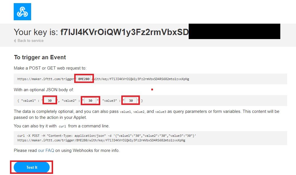
Note: This page contains an API key which we will use to send an HTTP POST request to the IFTTT trigger event (BME280).
(4) You will get a notification on top of the web page: “The event has been triggered”. Now go to your Gmail account and check for any notification that came from the IFTTT service. Open the message and it will display the dummy values you entered before:

If you also received a message with the same readings that you entered then it means that your applet is running successfully. It is now time to dig deeper into our project.
Now let’s move forward to write a MicroPython script for ESP32 and ESP8266 to send BME280 sensor reading in HTTP POST request to the IFTTT. In response IFTTT will send sensor values to our email address.
BME280 Introduction
The BME280 sensor is used to measure readings regarding ambient temperature, barometric pressure, and relative humidity. It is mostly used in web and mobile applications where low power consumption is key. This sensor uses I2C or SPI to communicate data with the micro-controllers. Although there are several different versions of BME280 available in the market, the one we will be studying uses I2C communication protocol and SPI.
I2C means Inter-Integrated Circuit and works on the principle of the synchronous, multi-master multi-slave system. With BME280 and the ESP boards, the ESP32/ESP8266 acts as a master, and the BME280 sensor as a slave because it is an external device, acts as a slave. The ESP development boards communicate with the BME280 sensor through the I2C protocol to temperature, barometric pressure, and relative humidity.
Pinout Diagram
The figure below shows the BME280 sensor and its pinout.
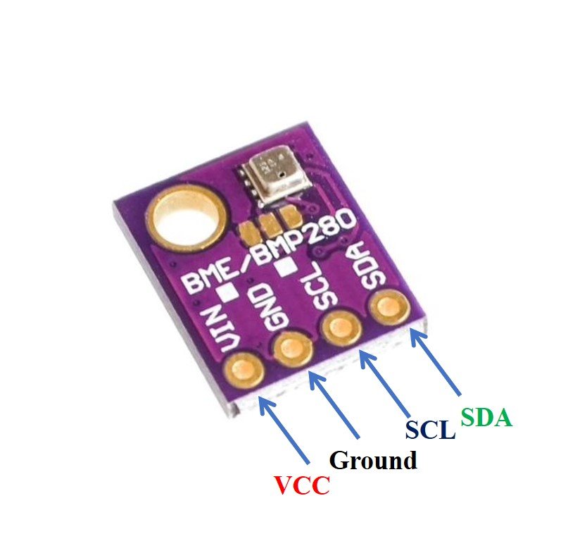
- VCC: connected with 3.3V
- SCL: used to generate the clock signal
- SDA: used in sending and receiving data
BME280 with ESP32 and ESP8266 Schematic
As discussed earlier, for this project, we use the BME280 sensor. But you can use any other sensor to send readings through email notification such as BME680, DHT11, DHT22, DS18B20, and LM35, etc.
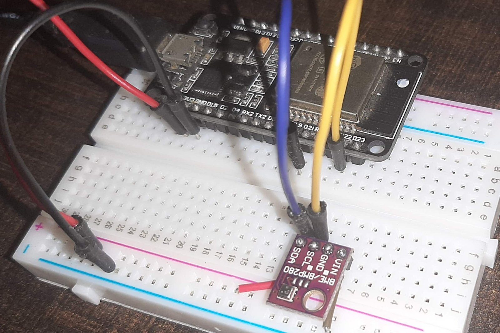
Now connect the ESP32 or ESP8266 NodeMCU module with BME280 sensor according to this table:
| ESP32 | ESP8266 | BME280 |
|---|---|---|
| VCC=3.3V | 3.3V | Vin |
| GPIO21(I2C SDA) | GPIO4 (D2) | SDA |
| GPIO22 (I2C SCL) | GPIO5 (D1) | SCL |
| GROUND | GROUND | GROUND |
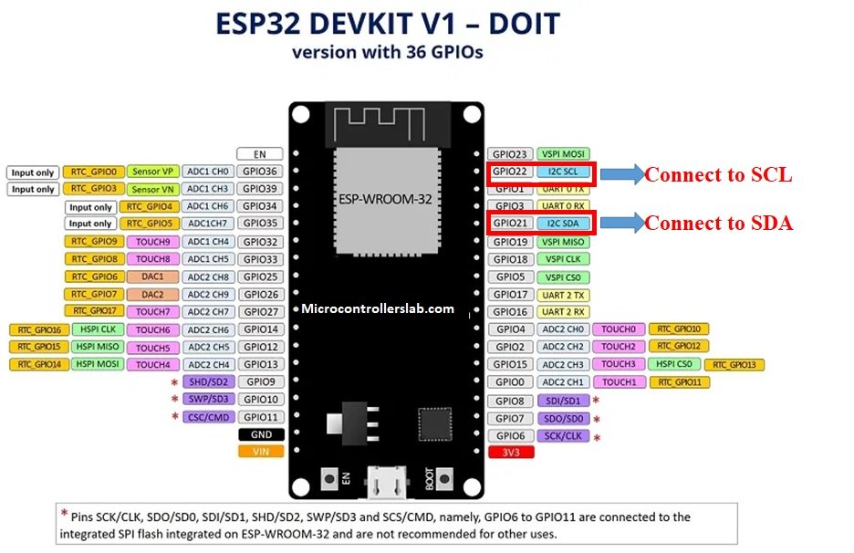
ESP32 I2C Pins
The I2C pins stated above are set in default. If we want to change the GPIO pins we have to set them in code. The diagrams below show the pinout for the ESP32 and Esp8266 respectively.
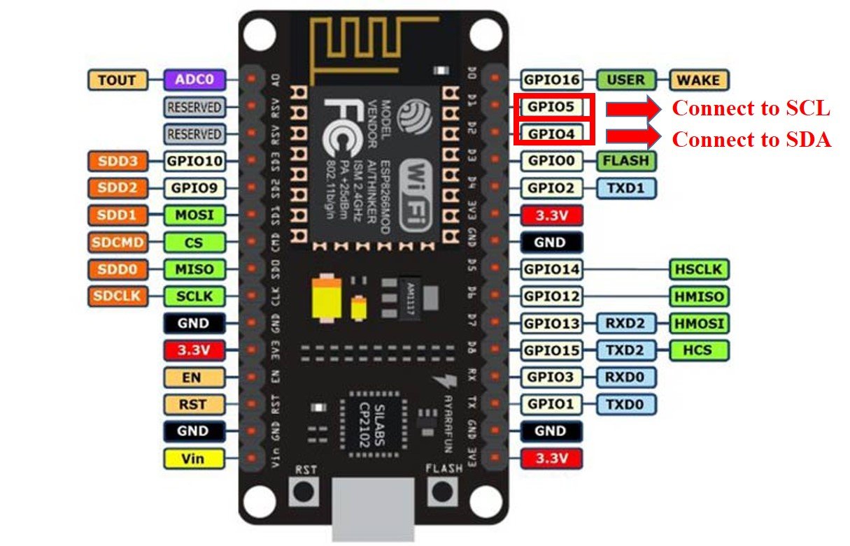
ESP8266 I2C Pins
The following figure shows the I2C pins of ESP8266 NodeMCU:
More information on ESP32 and ESP8266 pins is available here:
Components Required
We will need the following components to connect our ESP board with the BME280 sensor.
- ESP32/ESP8266
- BME280 Sensor
- Connecting Wires
- Breadboard
Schematic Diagrams
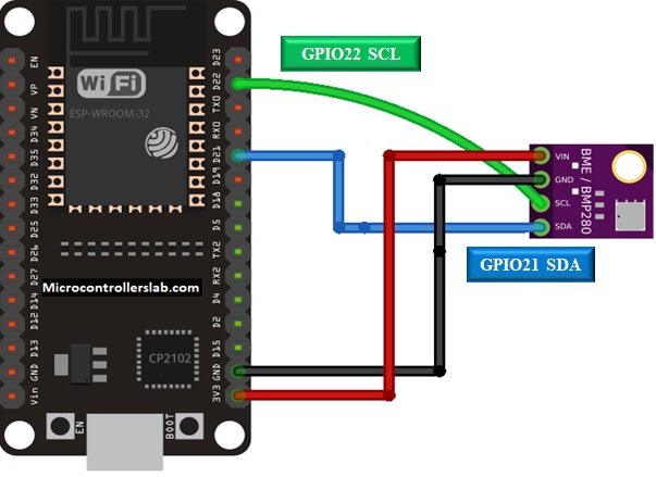
Follow the schematic diagrams below for both the ESP modules and connect them accordingly. If you are using ESP32 for this project, connect the ESP32 device with BME280 as shown in the schematic diagram below:
Similarly, if you are using ESP8266 NodeMCU for this project, connect the ESP8266 device with BME280 as shown in the schematic diagram below:
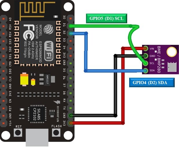
In some BME280 sensors as seen in the above connection diagram, the SCK terminal means the SCL pin and is connected with its respective GPIO pin on the ESP board. Likewise, the SDI terminal means the SDA pin and is connected with its respective GPIO pin on the board. Vin is connected with a 3.3V pin on the module and both the ESP board and the sensor is commonly grounded.
BME280 MicroPython Library
By default, MicroPython does not have an implementation of the BME280 library. But, MicroPyhon provides I2C API of ESP32 and ESP8266 which can be used to read the temperature, humidity, and pressure values from the BME280 sensor. Fortunately, there is one library available which is developed by Robert and can be downloaded from this link.
Hence, download the following library and upload it to ESP32/ESP8266 board with the name of BME280.py.
from machine import I2C
import time

# BME280 default address.
BME280_I2CADDR = 0x76

# Operating Modes
BME280_OSAMPLE_1 = 1
BME280_OSAMPLE_2 = 2
BME280_OSAMPLE_4 = 3
BME280_OSAMPLE_8 = 4
BME280_OSAMPLE_16 = 5

# BME280 Registers

BME280_REGISTER_DIG_T1 = 0x88  # Trimming parameter registers
BME280_REGISTER_DIG_T2 = 0x8A
BME280_REGISTER_DIG_T3 = 0x8C

BME280_REGISTER_DIG_P1 = 0x8E
BME280_REGISTER_DIG_P2 = 0x90
BME280_REGISTER_DIG_P3 = 0x92
BME280_REGISTER_DIG_P4 = 0x94
BME280_REGISTER_DIG_P5 = 0x96
BME280_REGISTER_DIG_P6 = 0x98
BME280_REGISTER_DIG_P7 = 0x9A
BME280_REGISTER_DIG_P8 = 0x9C
BME280_REGISTER_DIG_P9 = 0x9E

BME280_REGISTER_DIG_H1 = 0xA1
BME280_REGISTER_DIG_H2 = 0xE1
BME280_REGISTER_DIG_H3 = 0xE3
BME280_REGISTER_DIG_H4 = 0xE4
BME280_REGISTER_DIG_H5 = 0xE5
BME280_REGISTER_DIG_H6 = 0xE6
BME280_REGISTER_DIG_H7 = 0xE7

BME280_REGISTER_CHIPID = 0xD0
BME280_REGISTER_VERSION = 0xD1
BME280_REGISTER_SOFTRESET = 0xE0

BME280_REGISTER_CONTROL_HUM = 0xF2
BME280_REGISTER_CONTROL = 0xF4
BME280_REGISTER_CONFIG = 0xF5
BME280_REGISTER_PRESSURE_DATA = 0xF7
BME280_REGISTER_TEMP_DATA = 0xFA
BME280_REGISTER_HUMIDITY_DATA = 0xFD


class Device:
  """Class for communicating with an I2C device.

  Allows reading and writing 8-bit, 16-bit, and byte array values to
  registers on the device."""

  def __init__(self, address, i2c):
    """Create an instance of the I2C device at the specified address using
    the specified I2C interface object."""
    self._address = address
    self._i2c = i2c

  def writeRaw8(self, value):
    """Write an 8-bit value on the bus (without register)."""
    value = value & 0xFF
    self._i2c.writeto(self._address, value)

  def write8(self, register, value):
    """Write an 8-bit value to the specified register."""
    b=bytearray(1)
    b[0]=value & 0xFF
    self._i2c.writeto_mem(self._address, register, b)

  def write16(self, register, value):
    """Write a 16-bit value to the specified register."""
    value = value & 0xFFFF
    b=bytearray(2)
    b[0]= value & 0xFF
    b[1]= (value>>8) & 0xFF
    self.i2c.writeto_mem(self._address, register, value)

  def readRaw8(self):
    """Read an 8-bit value on the bus (without register)."""
    return int.from_bytes(self._i2c.readfrom(self._address, 1),'little') & 0xFF

  def readU8(self, register):
    """Read an unsigned byte from the specified register."""
    return int.from_bytes(
        self._i2c.readfrom_mem(self._address, register, 1),'little') & 0xFF

  def readS8(self, register):
    """Read a signed byte from the specified register."""
    result = self.readU8(register)
    if result > 127:
      result -= 256
    return result

  def readU16(self, register, little_endian=True):
    """Read an unsigned 16-bit value from the specified register, with the
    specified endianness (default little endian, or least significant byte
    first)."""
    result = int.from_bytes(
        self._i2c.readfrom_mem(self._address, register, 2),'little') & 0xFFFF
    if not little_endian:
      result = ((result << 8) & 0xFF00) + (result >> 8)
    return result

  def readS16(self, register, little_endian=True):
    """Read a signed 16-bit value from the specified register, with the
    specified endianness (default little endian, or least significant byte
    first)."""
    result = self.readU16(register, little_endian)
    if result > 32767:
      result -= 65536
    return result

  def readU16LE(self, register):
    """Read an unsigned 16-bit value from the specified register, in little
    endian byte order."""
    return self.readU16(register, little_endian=True)

  def readU16BE(self, register):
    """Read an unsigned 16-bit value from the specified register, in big
    endian byte order."""
    return self.readU16(register, little_endian=False)

  def readS16LE(self, register):
    """Read a signed 16-bit value from the specified register, in little
    endian byte order."""
    return self.readS16(register, little_endian=True)

  def readS16BE(self, register):
    """Read a signed 16-bit value from the specified register, in big
    endian byte order."""
    return self.readS16(register, little_endian=False)


class BME280:
  def __init__(self, mode=BME280_OSAMPLE_1, address=BME280_I2CADDR, i2c=None,
               **kwargs):
    # Check that mode is valid.
    if mode not in [BME280_OSAMPLE_1, BME280_OSAMPLE_2, BME280_OSAMPLE_4,
                    BME280_OSAMPLE_8, BME280_OSAMPLE_16]:
        raise ValueError(
            'Unexpected mode value {0}. Set mode to one of '
            'BME280_ULTRALOWPOWER, BME280_STANDARD, BME280_HIGHRES, or '
            'BME280_ULTRAHIGHRES'.format(mode))
    self._mode = mode
    # Create I2C device.
    if i2c is None:
      raise ValueError('An I2C object is required.')
    self._device = Device(address, i2c)
    # Load calibration values.
    self._load_calibration()
    self._device.write8(BME280_REGISTER_CONTROL, 0x3F)
    self.t_fine = 0

  def _load_calibration(self):

    self.dig_T1 = self._device.readU16LE(BME280_REGISTER_DIG_T1)
    self.dig_T2 = self._device.readS16LE(BME280_REGISTER_DIG_T2)
    self.dig_T3 = self._device.readS16LE(BME280_REGISTER_DIG_T3)

    self.dig_P1 = self._device.readU16LE(BME280_REGISTER_DIG_P1)
    self.dig_P2 = self._device.readS16LE(BME280_REGISTER_DIG_P2)
    self.dig_P3 = self._device.readS16LE(BME280_REGISTER_DIG_P3)
    self.dig_P4 = self._device.readS16LE(BME280_REGISTER_DIG_P4)
    self.dig_P5 = self._device.readS16LE(BME280_REGISTER_DIG_P5)
    self.dig_P6 = self._device.readS16LE(BME280_REGISTER_DIG_P6)
    self.dig_P7 = self._device.readS16LE(BME280_REGISTER_DIG_P7)
    self.dig_P8 = self._device.readS16LE(BME280_REGISTER_DIG_P8)
    self.dig_P9 = self._device.readS16LE(BME280_REGISTER_DIG_P9)

    self.dig_H1 = self._device.readU8(BME280_REGISTER_DIG_H1)
    self.dig_H2 = self._device.readS16LE(BME280_REGISTER_DIG_H2)
    self.dig_H3 = self._device.readU8(BME280_REGISTER_DIG_H3)
    self.dig_H6 = self._device.readS8(BME280_REGISTER_DIG_H7)

    h4 = self._device.readS8(BME280_REGISTER_DIG_H4)
    h4 = (h4 << 24) >> 20
    self.dig_H4 = h4 | (self._device.readU8(BME280_REGISTER_DIG_H5) & 0x0F)

    h5 = self._device.readS8(BME280_REGISTER_DIG_H6)
    h5 = (h5 << 24) >> 20
    self.dig_H5 = h5 | (
        self._device.readU8(BME280_REGISTER_DIG_H5) >> 4 & 0x0F)

  def read_raw_temp(self):
    """Reads the raw (uncompensated) temperature from the sensor."""
    meas = self._mode
    self._device.write8(BME280_REGISTER_CONTROL_HUM, meas)
    meas = self._mode << 5 | self._mode << 2 | 1
    self._device.write8(BME280_REGISTER_CONTROL, meas)
    sleep_time = 1250 + 2300 * (1 << self._mode)

    sleep_time = sleep_time + 2300 * (1 << self._mode) + 575
    sleep_time = sleep_time + 2300 * (1 << self._mode) + 575
    time.sleep_us(sleep_time)  # Wait the required time
    msb = self._device.readU8(BME280_REGISTER_TEMP_DATA)
    lsb = self._device.readU8(BME280_REGISTER_TEMP_DATA + 1)
    xlsb = self._device.readU8(BME280_REGISTER_TEMP_DATA + 2)
    raw = ((msb << 16) | (lsb << 8) | xlsb) >> 4
    return raw

  def read_raw_pressure(self):
    """Reads the raw (uncompensated) pressure level from the sensor."""
    """Assumes that the temperature has already been read """
    """i.e. that enough delay has been provided"""
    msb = self._device.readU8(BME280_REGISTER_PRESSURE_DATA)
    lsb = self._device.readU8(BME280_REGISTER_PRESSURE_DATA + 1)
    xlsb = self._device.readU8(BME280_REGISTER_PRESSURE_DATA + 2)
    raw = ((msb << 16) | (lsb << 8) | xlsb) >> 4
    return raw

  def read_raw_humidity(self):
    """Assumes that the temperature has already been read """
    """i.e. that enough delay has been provided"""
    msb = self._device.readU8(BME280_REGISTER_HUMIDITY_DATA)
    lsb = self._device.readU8(BME280_REGISTER_HUMIDITY_DATA + 1)
    raw = (msb << 8) | lsb
    return raw

  def read_temperature(self):
    """Get the compensated temperature in 0.01 of a degree celsius."""
    adc = self.read_raw_temp()
    var1 = ((adc >> 3) - (self.dig_T1 << 1)) * (self.dig_T2 >> 11)
    var2 = ((
        (((adc >> 4) - self.dig_T1) * ((adc >> 4) - self.dig_T1)) >> 12) *
        self.dig_T3) >> 14
    self.t_fine = var1 + var2
    return (self.t_fine * 5 + 128) >> 8

  def read_pressure(self):
    """Gets the compensated pressure in Pascals."""
    adc = self.read_raw_pressure()
    var1 = self.t_fine - 128000
    var2 = var1 * var1 * self.dig_P6
    var2 = var2 + ((var1 * self.dig_P5) << 17)
    var2 = var2 + (self.dig_P4 << 35)
    var1 = (((var1 * var1 * self.dig_P3) >> 8) +
            ((var1 * self.dig_P2) >> 12))
    var1 = (((1 << 47) + var1) * self.dig_P1) >> 33
    if var1 == 0:
      return 0
    p = 1048576 - adc
    p = (((p << 31) - var2) * 3125) // var1
    var1 = (self.dig_P9 * (p >> 13) * (p >> 13)) >> 25
    var2 = (self.dig_P8 * p) >> 19
    return ((p + var1 + var2) >> 8) + (self.dig_P7 << 4)

  def read_humidity(self):
    adc = self.read_raw_humidity()
    # print 'Raw humidity = {0:d}'.format (adc)
    h = self.t_fine - 76800
    h = (((((adc << 14) - (self.dig_H4 << 20) - (self.dig_H5 * h)) +
         16384) >> 15) * (((((((h * self.dig_H6) >> 10) * (((h *
                          self.dig_H3) >> 11) + 32768)) >> 10) + 2097152) *
                          self.dig_H2 + 8192) >> 14))
    h = h - (((((h >> 15) * (h >> 15)) >> 7) * self.dig_H1) >> 4)
    h = 0 if h < 0 else h
    h = 419430400 if h > 419430400 else h
    return h >> 12

  @property
  def temperature(self):
    "Return the temperature in degrees."
    t = self.read_temperature()
    ti = t // 100
    td = t - ti * 100
    return "{}.{:02d}C".format(ti, td)

  @property
  def pressure(self):
    "Return the temperature in hPa."
    p = self.read_pressure() // 256
    pi = p // 100
    pd = p - pi * 100
    return "{}.{:02d}hPa".format(pi, pd)

  @property
  def humidity(self):
    "Return the humidity in percent."
    h = self.read_humidity()
    hi = h // 1024
    hd = h * 100 // 1024 - hi * 100
return "{}.{:02d}%".format(hi, hd)Uploading BME280 Library with uPyCraft IDE
Now, we will look at how to install the BME280 library to be used in MicroPython. This step is required because MicroPython itself does not contain the sensor’s library. Follow the steps in order to successfully install the library in the IDE.
- First, in the Tools section, click on the NEW FILE button and open a file.

- Then replicate the following BME280 library in that file. You can copy the library by clicking here.
- Name the file BME280.py and save it by choosing your desired directory.

- Now press the button DOWNLOAD AND RUN in the tools section.

You have now successfully uploaded the BME280 library to ESP32/ESP8266 using uPyCraft IDE. After that, we can use the above library functions to read temperature, pressure, and humidity from the BM280 sensor. You can use a similar procedure to upload files using Thonny IDE.
Uploading BME280 Library in Thonny IDE
If you are using Thonny IDE , open a new file and copy the code as we did in uPyCraft IDE.
- Save the file as BME280.py
- In addition, head over to Device> Upload Current Script with Current Name
You have successfully installed the BME280 library in Thonny IDE.
MicroPython Script: Send Sensor Readings via Email (IFTTT)
As discussed earlier, we want to send the BME280 sensor reading through email whenever the ESP32/ESP8266 devic boots up. Therefore, we will add the HTTP POST request MicroPython code in our boot.py file.
For this project, we only need the boot.py file. Write down the code which is given below in your boot.py file. Make sure both your boot.py and BME280.py are uploaded to ESP32/ESP8266 board.
from machine import Pin, I2C
import BME280
import network
import urequests

import esp
esp.osdebug(None)

import gc
gc.collect()

ssid = 'Enter_Your_WiFi_Name'
password = 'WiFi_Password'

api_key = 'Enter_Your_API_Key'

station = network.WLAN(network.STA_IF)

station.active(True)
station.connect(ssid, password)

while station.isconnected() == False:
  pass

print('Connection successful')
print(station.ifconfig())

# ESP32 - Pin assignement
i2c = I2C(scl=Pin(22), sda=Pin(21), freq=10000)
# ESP8266 - Pin assignement
#i2c = I2C(scl=Pin(5), sda=Pin(4), freq=10000)

try:
  bme = BME280.BME280(i2c=i2c)
  temp = bme.temperature
  hum = bme.humidity
  pres = bme.pressure

  # uncomment for temperature in Fahrenheit
  #temp = (bme.read_temperature()/100) * (9/5) + 32
  #temp = str(round(temp, 2)) + 'F'

  sensor_readings = {'value1':temp, 'value2':hum, 'value3':pres}
  print('Printing sensorredings')
  print(sensor_readings)

  request_headers = {'Content-Type': 'application/json'}

  request = urequests.post(
    'https://maker.ifttt.com/trigger/BME280/with/key/' + api_key,
    json=sensor_readings,
    headers=request_headers)
  print(request.text)
  request.close()

except OSError as e:
  print('Failed to read/publish sensor readings.')
How the Code Works?
Import Libraries
To start off, we will import the Pin and the I2C classes from the machine module. We will also import the BME280 library which we uploaded earlier. By importing network, we are able to connect with our local network. The urequests library helps us in making the HTTP requests which we will be making to the IFTTT service.
from machine import Pin, I2C
import BME280
import network
import urequests

import esp
esp.osdebug(None)

import gc
gc.collect()
Connect to WiFi
Then, we will specify our wi-fi name and its password so that the ESP32/ESP8266 is able to connect with the local network. We will also you inserting the unique API key which we obtained from the Webhooks IFTTT service.
ssid = 'Enter_Your_WiFi_Name'
password = 'WiFi_Password'
api_key = 'Enter_Your_API_Key'
Next, we will connect our ESP boards with the router. Here the boards act in the Station Mode and the router is the Access Point. We will be printing the ESP32/ESP8266 IP address as a result.
station = network.WLAN(network.STA_IF)

station.active(True)
station.connect(ssid, password)

while station.isconnected() == False:
  pass

print('Connection successful')
print(station.ifconfig())
Define I2C Pins ESP32/ESP8266
Next, we will be setting the default I2C GPIO pins to connect the BME280 sensor and the ESP32/ESP8266 development boards. We will create the I2C() method by passing in three parameters. The first parameter is the SCL pin which we set up as GPIO pin 22 for ESP32 and GPIO pin 5 for ESP8266. The second parameter is the SDA pin which we set up as GPIO pin 21 for ESP32 and GPIO pin 4 for ESP8266. These are the default pins for both boards. The third parameter is the frequency which we will set as 10000Hz.
For ESP32 we will be using the following command.
i2c = I2C(scl=Pin(22), sda=Pin(21), freq=10000)For ESP8266, uncomment this command and comment the command intended for ESP32
#i2c = I2C(scl=Pin(5), sda=Pin(4), freq=10000)Then, we will incorporate try and except statements in our code. This will help us in case of a failure in connection. If that happens an error message will be printed otherwise the try statements will be implemented in which we will be reading the values from the sensor and publishing them.
except OSError as e:
print('Failed to read/publish sensor readings.')
Getting Sesnor Reading
We will then create an instance of the BME280 object as bme and use it to access the readings of temperature, humidity, and pressure. These readings get saved in their respective variables.
bme = BME280.BME280(i2c=i2c)
temperature = bme.temperature
humidity = bme.humidity
pressure = bme.pressure
Making HTTP Post Request to IFTTT
Now, we will be using the urequests library to make a HTTP post request. This will transmit the sensor readings to the IFTTT. We will be creating a general post request with three parameters.
request= requests.post(url, json=json_data, headers=headers)The first parameter specifies the URL in which we will make the request. We will be using the URL: http://maker.ifttt.com/trigger/BME280/with/key/api_key and replace api_key with our own unique API IFTTT key which we specified before as well. The second parameter is JSON (JavaScript Object Notation) which shows that the data transferred would be in this format. It is used as a default for exchanging data. The data will be the three sensor readings.
sensor_readings = {'value1':temperature, 'value2':humidity, 'value3':pressure}The third parameter is the header which contains the information regarding the request.
request_headers = {'Content-Type': 'application/json'}Thus, we will incorporate all these three parameters in making the request by using the post() method.
equest = urequests.post(
    'https://maker.ifttt.com/trigger/BME280/with/key/' + api_key,
    json=sensor_readings,
    headers=request_headers)
In the end we will close the request and print the request for debugging.
print(request.text)
request.close()
Demonstration
Upload BME280.py and boot.py files to your ESP32 or ESP8266 boards. After that you will get an email notification from IFTTT with BME280 sensor readings as shown below:

You will also get the output on MicroPython shell console like this:
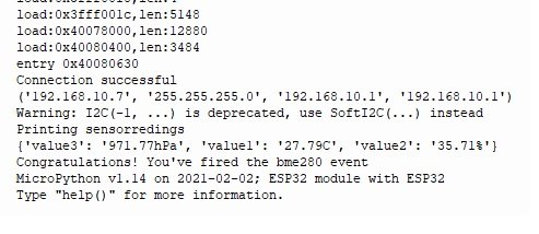
In this article, we had a look at IFTTT and how to send sensor reading via email from our ESP32/ESP8266 boards using MicroPython firmware.
If you want to send BME680 sensor reading through email instead of BM280, you can read this guide on BME680:
You may also like to check similar guides with ESP32 and ESP8266 using Arduino IDE:
- HTTP GET using ESP32 and Arduino IDE (OpenWeatherMap.org and ThingSpeak)
- ESP32 HTTP POST using Arduino IDE (ThingSpeak and IFTTT)
You may also like to read: