In this user guide, we will take a look at the BME280 sensor which is used to pressure, humidity, and temperature. Firstly, we will learn about BME280 and how to connect with Esp32 and with Esp8266. Secondly, we will write and upload its library in our Integrated Development Environment (uPyCraft IDE). Next, we will work on a simple example to demonstrate its working and lastly, we will measure Temperature, Humidity, and Pressure.
Prerequisites
Before we start this lesson make sure you are familiar with and have the latest version of MicroPython firmware installed in your ESP boards and have a running Integrated Development Environment(IDE) in which we will be doing the programming. We will be using the same uPyCraft IDE as we have done previously when we learned how to blink and chase LEDs in microPython.
- Getting Started with MicroPython on ESP32 and ESP8266
- ESP32 and ESP8266 GPIO Programming with MicroPython – LED Blinking Example
If you are using Thonny IDE, you can check this getting started guide:
We will cover the following content in this MicroPython tutorial:
- How to create a BM280 web server using ESP32/ESP8266 and MicroPython
- Display Temperature, Humidity, and Pressure readings on a web page with ESP32 and ESP8266
BME280 Introduction
The BME280 sensor is used to measure readings regarding ambient temperature, barometric pressure, and relative humidity. It is mostly used in web and mobile applications where low power consumption is key. This sensor uses I2C or SPI to communicate data with the micro-controllers. Although there are several different versions of BME280 available in the market, the one we will be studying uses I2C communication protocol and SPI.
I2C means Inter-Integrated Circuit and works on the principle of the synchronous, multi-master multi-slave system. With BME280 and the ESP boards, the ESP32/ESP8266 acts as a master, and the BME280 sensor as a slave because it is an external device, acts as a slave. The ESP development boards communicate with the BME280 sensor through the I2C protocol to temperature, barometric pressure, and relative humidity.
Pinout Diagram
The figure below shows the BME280 sensor and its pinout.
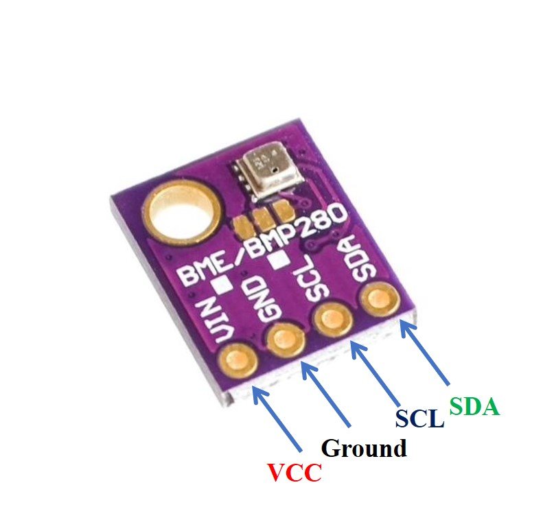
- VCC: connected with 3.3V
- SCL: used to generate the clock signal
- SDA: used in sending and receiving data
ESP32 and ESP8266 Schematic with BME280
The connection of BME280 with the ESP boards is very easy. We have to connect the VCC terminal with 3.3V, ground with the ground (common ground), SCL of the sensor with SCL of the module, and SDA of the sensor with the SDA pin of the ESP modules.
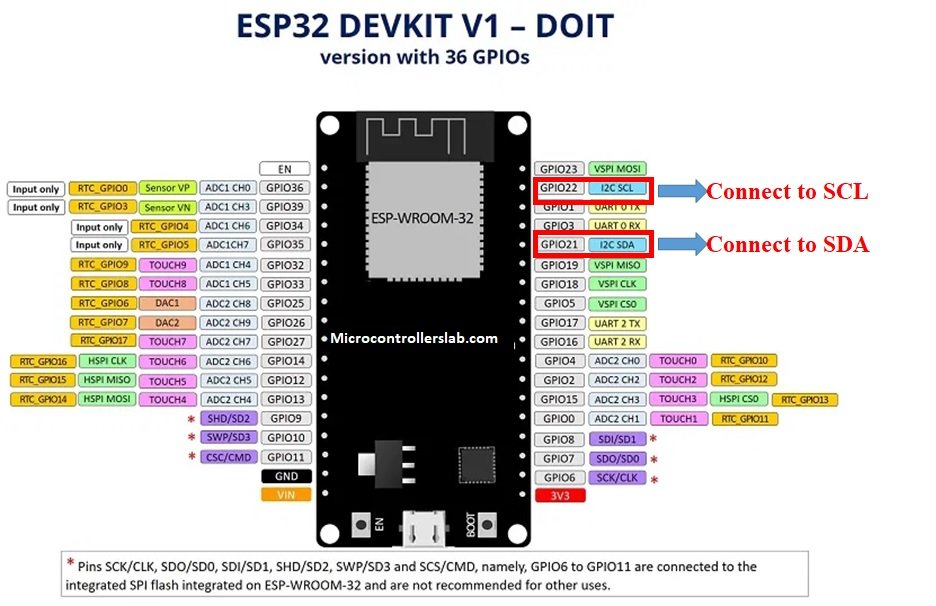
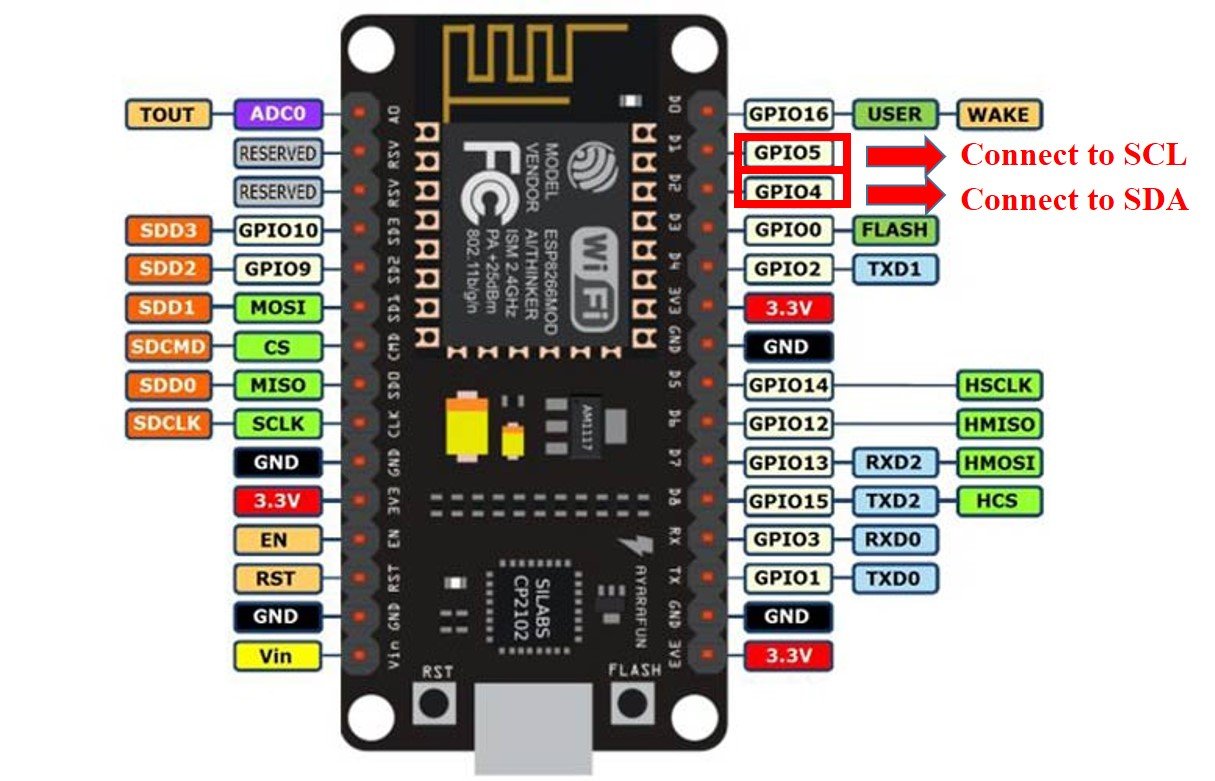
The I2C pin in ESP32 for SDA is GPIO21 and for SCL is GPIO22. Whereas, in ESP8266 the default I2C pins for SDA are GPIO4 and for SCL are GPIO5. The connections between the two devices can be seen below.
| ESP32 | ESP8266 | BME280 |
|---|---|---|
| VCC=3.3V | 3.3V | Vin |
| GPIO21(I2C SDA) | GPIO4 (D2) | SDA |
| GPIO22 (I2C SCL) | GPIO5 (D1) | SCL |
| GROUND | GROUND | GROUND |
ESP32 I2C Pins
The I2C pins stated above are set in default. If we want to change the GPIO pins we have to set them in code. The diagrams below show the pinout for the ESP32 and Esp8266 respectively.
ESP8266 I2C Pins
The following figure shows the I2C pins of ESP8266 NodeMCU:
More information on ESP32 and ESP8266 pins is available here:
Components Required
We will need the following components to connect our ESP board with the BME280 sensor.
- ESP32/ESP8266
- BME280 Sensor
- Connecting Wires
- Breadboard
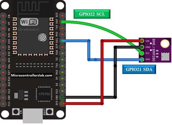
Follow the schematic diagrams below for both the ESP modules and connect them accordingly. If you are using ESP32 for this project, connect the ESP32 device with BME280 as shown in the schematic diagram below:
Similarly, you are using ESP8266 NodeMCU for this project, connect the ESP8266 device with BME280 as shown in the schematic diagram below:
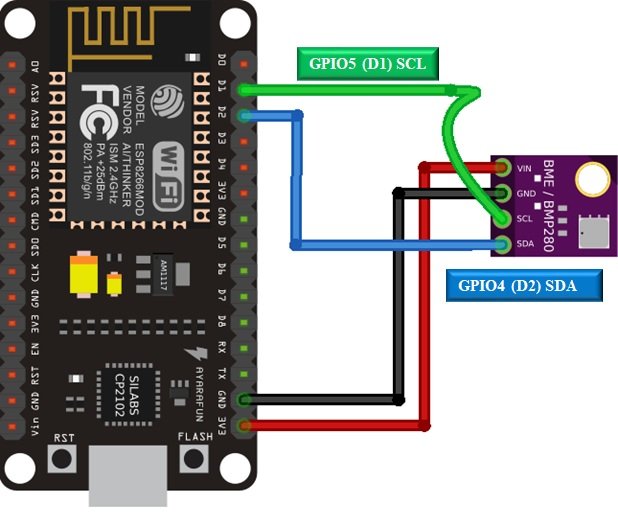
In some BME280 sensors as seen in the above connection diagram, the SCK terminal means the SCL pin and is connected with its respective GPIO pin on the ESP board. Likewise, the SDI terminal means the SDA pin and is connected with its respective GPIO pin on the board. Vin is connected with a 3.3V pin on the module and both the ESP board and the sensor is commonly grounded.
BME280 MicroPython Library
By default, MicroPython does not have an implementation of the BME280 library. But, MicroPyhon provides I2C API of ESP32 and ESP8266 which can be used to read the temperature, humidity, and pressure values from the BME280 sensor. Fortunately, there is one library available which is developed by Robert and can be downloaded from this link.
Hence, download the following library and upload it to ESP32/ESP8266 board with the name of BME280.py.
from machine import I2C
import time

# BME280 default address.
BME280_I2CADDR = 0x76

# Operating Modes
BME280_OSAMPLE_1 = 1
BME280_OSAMPLE_2 = 2
BME280_OSAMPLE_4 = 3
BME280_OSAMPLE_8 = 4
BME280_OSAMPLE_16 = 5

# BME280 Registers

BME280_REGISTER_DIG_T1 = 0x88  # Trimming parameter registers
BME280_REGISTER_DIG_T2 = 0x8A
BME280_REGISTER_DIG_T3 = 0x8C

BME280_REGISTER_DIG_P1 = 0x8E
BME280_REGISTER_DIG_P2 = 0x90
BME280_REGISTER_DIG_P3 = 0x92
BME280_REGISTER_DIG_P4 = 0x94
BME280_REGISTER_DIG_P5 = 0x96
BME280_REGISTER_DIG_P6 = 0x98
BME280_REGISTER_DIG_P7 = 0x9A
BME280_REGISTER_DIG_P8 = 0x9C
BME280_REGISTER_DIG_P9 = 0x9E

BME280_REGISTER_DIG_H1 = 0xA1
BME280_REGISTER_DIG_H2 = 0xE1
BME280_REGISTER_DIG_H3 = 0xE3
BME280_REGISTER_DIG_H4 = 0xE4
BME280_REGISTER_DIG_H5 = 0xE5
BME280_REGISTER_DIG_H6 = 0xE6
BME280_REGISTER_DIG_H7 = 0xE7

BME280_REGISTER_CHIPID = 0xD0
BME280_REGISTER_VERSION = 0xD1
BME280_REGISTER_SOFTRESET = 0xE0

BME280_REGISTER_CONTROL_HUM = 0xF2
BME280_REGISTER_CONTROL = 0xF4
BME280_REGISTER_CONFIG = 0xF5
BME280_REGISTER_PRESSURE_DATA = 0xF7
BME280_REGISTER_TEMP_DATA = 0xFA
BME280_REGISTER_HUMIDITY_DATA = 0xFD


class Device:
  """Class for communicating with an I2C device.

  Allows reading and writing 8-bit, 16-bit, and byte array values to
  registers on the device."""

  def __init__(self, address, i2c):
    """Create an instance of the I2C device at the specified address using
    the specified I2C interface object."""
    self._address = address
    self._i2c = i2c

  def writeRaw8(self, value):
    """Write an 8-bit value on the bus (without register)."""
    value = value & 0xFF
    self._i2c.writeto(self._address, value)

  def write8(self, register, value):
    """Write an 8-bit value to the specified register."""
    b=bytearray(1)
    b[0]=value & 0xFF
    self._i2c.writeto_mem(self._address, register, b)

  def write16(self, register, value):
    """Write a 16-bit value to the specified register."""
    value = value & 0xFFFF
    b=bytearray(2)
    b[0]= value & 0xFF
    b[1]= (value>>8) & 0xFF
    self.i2c.writeto_mem(self._address, register, value)

  def readRaw8(self):
    """Read an 8-bit value on the bus (without register)."""
    return int.from_bytes(self._i2c.readfrom(self._address, 1),'little') & 0xFF

  def readU8(self, register):
    """Read an unsigned byte from the specified register."""
    return int.from_bytes(
        self._i2c.readfrom_mem(self._address, register, 1),'little') & 0xFF

  def readS8(self, register):
    """Read a signed byte from the specified register."""
    result = self.readU8(register)
    if result > 127:
      result -= 256
    return result

  def readU16(self, register, little_endian=True):
    """Read an unsigned 16-bit value from the specified register, with the
    specified endianness (default little endian, or least significant byte
    first)."""
    result = int.from_bytes(
        self._i2c.readfrom_mem(self._address, register, 2),'little') & 0xFFFF
    if not little_endian:
      result = ((result << 8) & 0xFF00) + (result >> 8)
    return result

  def readS16(self, register, little_endian=True):
    """Read a signed 16-bit value from the specified register, with the
    specified endianness (default little endian, or least significant byte
    first)."""
    result = self.readU16(register, little_endian)
    if result > 32767:
      result -= 65536
    return result

  def readU16LE(self, register):
    """Read an unsigned 16-bit value from the specified register, in little
    endian byte order."""
    return self.readU16(register, little_endian=True)

  def readU16BE(self, register):
    """Read an unsigned 16-bit value from the specified register, in big
    endian byte order."""
    return self.readU16(register, little_endian=False)

  def readS16LE(self, register):
    """Read a signed 16-bit value from the specified register, in little
    endian byte order."""
    return self.readS16(register, little_endian=True)

  def readS16BE(self, register):
    """Read a signed 16-bit value from the specified register, in big
    endian byte order."""
    return self.readS16(register, little_endian=False)


class BME280:
  def __init__(self, mode=BME280_OSAMPLE_1, address=BME280_I2CADDR, i2c=None,
               **kwargs):
    # Check that mode is valid.
    if mode not in [BME280_OSAMPLE_1, BME280_OSAMPLE_2, BME280_OSAMPLE_4,
                    BME280_OSAMPLE_8, BME280_OSAMPLE_16]:
        raise ValueError(
            'Unexpected mode value {0}. Set mode to one of '
            'BME280_ULTRALOWPOWER, BME280_STANDARD, BME280_HIGHRES, or '
            'BME280_ULTRAHIGHRES'.format(mode))
    self._mode = mode
    # Create I2C device.
    if i2c is None:
      raise ValueError('An I2C object is required.')
    self._device = Device(address, i2c)
    # Load calibration values.
    self._load_calibration()
    self._device.write8(BME280_REGISTER_CONTROL, 0x3F)
    self.t_fine = 0

  def _load_calibration(self):

    self.dig_T1 = self._device.readU16LE(BME280_REGISTER_DIG_T1)
    self.dig_T2 = self._device.readS16LE(BME280_REGISTER_DIG_T2)
    self.dig_T3 = self._device.readS16LE(BME280_REGISTER_DIG_T3)

    self.dig_P1 = self._device.readU16LE(BME280_REGISTER_DIG_P1)
    self.dig_P2 = self._device.readS16LE(BME280_REGISTER_DIG_P2)
    self.dig_P3 = self._device.readS16LE(BME280_REGISTER_DIG_P3)
    self.dig_P4 = self._device.readS16LE(BME280_REGISTER_DIG_P4)
    self.dig_P5 = self._device.readS16LE(BME280_REGISTER_DIG_P5)
    self.dig_P6 = self._device.readS16LE(BME280_REGISTER_DIG_P6)
    self.dig_P7 = self._device.readS16LE(BME280_REGISTER_DIG_P7)
    self.dig_P8 = self._device.readS16LE(BME280_REGISTER_DIG_P8)
    self.dig_P9 = self._device.readS16LE(BME280_REGISTER_DIG_P9)

    self.dig_H1 = self._device.readU8(BME280_REGISTER_DIG_H1)
    self.dig_H2 = self._device.readS16LE(BME280_REGISTER_DIG_H2)
    self.dig_H3 = self._device.readU8(BME280_REGISTER_DIG_H3)
    self.dig_H6 = self._device.readS8(BME280_REGISTER_DIG_H7)

    h4 = self._device.readS8(BME280_REGISTER_DIG_H4)
    h4 = (h4 << 24) >> 20
    self.dig_H4 = h4 | (self._device.readU8(BME280_REGISTER_DIG_H5) & 0x0F)

    h5 = self._device.readS8(BME280_REGISTER_DIG_H6)
    h5 = (h5 << 24) >> 20
    self.dig_H5 = h5 | (
        self._device.readU8(BME280_REGISTER_DIG_H5) >> 4 & 0x0F)

  def read_raw_temp(self):
    """Reads the raw (uncompensated) temperature from the sensor."""
    meas = self._mode
    self._device.write8(BME280_REGISTER_CONTROL_HUM, meas)
    meas = self._mode << 5 | self._mode << 2 | 1
    self._device.write8(BME280_REGISTER_CONTROL, meas)
    sleep_time = 1250 + 2300 * (1 << self._mode)

    sleep_time = sleep_time + 2300 * (1 << self._mode) + 575
    sleep_time = sleep_time + 2300 * (1 << self._mode) + 575
    time.sleep_us(sleep_time)  # Wait the required time
    msb = self._device.readU8(BME280_REGISTER_TEMP_DATA)
    lsb = self._device.readU8(BME280_REGISTER_TEMP_DATA + 1)
    xlsb = self._device.readU8(BME280_REGISTER_TEMP_DATA + 2)
    raw = ((msb << 16) | (lsb << 8) | xlsb) >> 4
    return raw

  def read_raw_pressure(self):
    """Reads the raw (uncompensated) pressure level from the sensor."""
    """Assumes that the temperature has already been read """
    """i.e. that enough delay has been provided"""
    msb = self._device.readU8(BME280_REGISTER_PRESSURE_DATA)
    lsb = self._device.readU8(BME280_REGISTER_PRESSURE_DATA + 1)
    xlsb = self._device.readU8(BME280_REGISTER_PRESSURE_DATA + 2)
    raw = ((msb << 16) | (lsb << 8) | xlsb) >> 4
    return raw

  def read_raw_humidity(self):
    """Assumes that the temperature has already been read """
    """i.e. that enough delay has been provided"""
    msb = self._device.readU8(BME280_REGISTER_HUMIDITY_DATA)
    lsb = self._device.readU8(BME280_REGISTER_HUMIDITY_DATA + 1)
    raw = (msb << 8) | lsb
    return raw

  def read_temperature(self):
    """Get the compensated temperature in 0.01 of a degree celsius."""
    adc = self.read_raw_temp()
    var1 = ((adc >> 3) - (self.dig_T1 << 1)) * (self.dig_T2 >> 11)
    var2 = ((
        (((adc >> 4) - self.dig_T1) * ((adc >> 4) - self.dig_T1)) >> 12) *
        self.dig_T3) >> 14
    self.t_fine = var1 + var2
    return (self.t_fine * 5 + 128) >> 8

  def read_pressure(self):
    """Gets the compensated pressure in Pascals."""
    adc = self.read_raw_pressure()
    var1 = self.t_fine - 128000
    var2 = var1 * var1 * self.dig_P6
    var2 = var2 + ((var1 * self.dig_P5) << 17)
    var2 = var2 + (self.dig_P4 << 35)
    var1 = (((var1 * var1 * self.dig_P3) >> 8) +
            ((var1 * self.dig_P2) >> 12))
    var1 = (((1 << 47) + var1) * self.dig_P1) >> 33
    if var1 == 0:
      return 0
    p = 1048576 - adc
    p = (((p << 31) - var2) * 3125) // var1
    var1 = (self.dig_P9 * (p >> 13) * (p >> 13)) >> 25
    var2 = (self.dig_P8 * p) >> 19
    return ((p + var1 + var2) >> 8) + (self.dig_P7 << 4)

  def read_humidity(self):
    adc = self.read_raw_humidity()
    # print 'Raw humidity = {0:d}'.format (adc)
    h = self.t_fine - 76800
    h = (((((adc << 14) - (self.dig_H4 << 20) - (self.dig_H5 * h)) +
         16384) >> 15) * (((((((h * self.dig_H6) >> 10) * (((h *
                          self.dig_H3) >> 11) + 32768)) >> 10) + 2097152) *
                          self.dig_H2 + 8192) >> 14))
    h = h - (((((h >> 15) * (h >> 15)) >> 7) * self.dig_H1) >> 4)
    h = 0 if h < 0 else h
    h = 419430400 if h > 419430400 else h
    return h >> 12

  @property
  def temperature(self):
    "Return the temperature in degrees."
    t = self.read_temperature()
    ti = t // 100
    td = t - ti * 100
    return "{}.{:02d}C".format(ti, td)

  @property
  def pressure(self):
    "Return the temperature in hPa."
    p = self.read_pressure() // 256
    pi = p // 100
    pd = p - pi * 100
    return "{}.{:02d}hPa".format(pi, pd)

  @property
  def humidity(self):
    "Return the humidity in percent."
    h = self.read_humidity()
    hi = h // 1024
    hd = h * 100 // 1024 - hi * 100
return "{}.{:02d}%".format(hi, hd)Uploading BME280 Library with uPyCraft IDE
Now, we will look at how to install the BME280 library to be used in MicroPython. This step is required because MicroPython itself does not contain the sensor’s library. Follow the steps in order to successfully install the library in the IDE.
- First, in the Tools section, click on the NEW FILE button and open a file.

- Then replicate the following BME280 library in that file. You can copy the library by clicking here.
- Name the file BME280.py and save it by choosing your desired directory.

- Now press the button DOWNLOAD AND RUN in the tools section.

You have now successfully uploaded the BME280 library o ESP32/ESP8266 using uPyCraft IDE. After that, we can use the above library functions to read temperature, pressure, and humidity from the BM280 sensor. You can use a similar procedure to upload files using Thonny IDE.
Measuring Temperature, Pressure & Humidity with BME280
As we have already uploaded the BME280 library to ESP32/ESP8266 boards. Now we can use the functions available in the BME280 library to get sensor readings.
Let’s now look at an example to show the working of the sensor. We will connect our BME280 sensor with the ESP module via the I2C protocol as shown above in the connection diagrams. We will see a MicroPython script code and after uploading it to our ESP boards, we will see readings of temperature, pressure, and relative humidity printed on the MicroPython shell terminal.
BME280 MicroPython Code
Now let’s look at the MicroPython script for BME280 to get sensor readings. Copy the following code to the main.py file and upload the main.py file to ESP32/ESP8266. This microPython script reads Pressure, Temperature and Humidity values from BME280 over I2C lines and prints them on MicroPython shell console.
from machine import Pin, I2C        #importing relevant modules & classes
from time import sleep
import BME280        #importing BME280 library

i2c = I2C(scl=Pin(22), sda=Pin(21), freq=10000)     #initializing the I2C method for ESP32
#i2c = I2C(scl=Pin(5), sda=Pin(4), freq=10000)       #initializing the I2C method for ESP8266

while True:
  bme = BME280.BME280(i2c=i2c)          #BME280 object created
  temperature = bme.temperature            #reading the value of temperature
  humidity = bme.humidity                     #reading the value of humidity
  pressure = bme.pressure                     #reading the value of pressure

  print('Temperature is: ', temperature)    #printing BME280 values
  print('Humidity is: ', humidity)
  print('Pressure is: ', pressure)
  sleep(10)           #delay of 10s
How the Code Works?
Firstly, we will be importing the Pin class and I2C class from the machine module. This is because we have to specify the pin for I2C communication. We also import the sleep module so that we will be able to add a delay of 10 seconds in between our readings. Also, import the BME280 library which we have previously uploaded to ESP32 or ESP8266.
from machine import Pin, I2C        #importing relevant modules & classes
from time import sleep
import BME280        #importing BME280 library
Defining ESP32/ESP8266 GPIO Pins for BME280
Now, we initialize the I2C method by giving it three arguments. The first argument specifies the GPIO pin for SCL. This is given as GPIO22 for ESP32 and GPIO5 for ESP8266. The second parameter specifies the GPIO pin for the SDA. This is given as GPIO21 for ESP32 and GPIO4 for ESP8266. Keep in mind, these are the default I2C pins for SCL and SDA which we have used for both the ESP boards respectively. The third parameter specifies the maximum frequency for SCL to be used.
i2c = I2C(scl=Pin(22), sda=Pin(21), freq=10000)     #initializing the I2C method for ESP32
#i2c = I2C(scl=Pin(5), sda=Pin(4), freq=10000)       #initializing the I2C method for ESP8266
Next, we run an infinite loop inside which we create an object of BME280 named bme and access the temperature, humidity and pressure through it.
while True:
  bme = BME280.BME280(i2c=i2c)          #BME280 object created
  temperature = bme.temperature            #reading the value of temperature
  humidity = bme.humidity                     #reading the value of humidity
  pressure = bme.pressure                     #reading the value of pressure
Finally, we will print the individual values in the terminal by giving the print command. We also add a delay of 10s after each set of readings are displayed.
print('Temperature is: ', temperature)    #printing BME280 values
print('Humidity is: ', humidity)
print('Pressure is: ', pressure)
sleep(10)           #delay of 10s
Demo
To test the MicroPython script for BME280 with ESP32 and ESP8266, upload all main.py file to ESP32/ESP8266. After uploading the MicroPython script, click on Enable/Reset button of ESP32 or ESP8266:

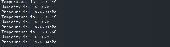
You will see Pressure, Temperature and Humidity readings on shell console:
MicroPython: Displaying BME280 Sensor values on OLED Display
In this section, we will see how to display BME280 Pressure, Temperature, Humidity values on a 0.96 SSD1306 OLED display using MicroPython and ESP32/ESP8266.
SSD1306 OLED Display MicroPython Library
We have already uploaded the BME280 MicroPython library to ESP32 and ESP8266 NodeMCU. For an OLED display, we will also need to upload a library to ESP boards.
Copy the following code which is a MicroPython library of OLED and upload the library using either uPycraft or Thonny IDE by giving it the name of ssd1306.py. You should follow the same procedure to upload the library as we did for bme280.py.
# MicroPython SSD1306 OLED driver, I2C and SPI interfaces
from micropython import const
import time
import framebuf
import sys

currentBoard=""
if(sys.platform=="esp8266"):
  currentBoard="esp8266"
elif(sys.platform=="esp32"):
  currentBoard="esp32"
elif(sys.platform=="pyboard"):
  currentBoard="pyboard"
  import pyb
# register definitions
SET_CONTRAST        = const(0x81)
SET_ENTIRE_ON       = const(0xa4)
SET_NORM_INV        = const(0xa6)
SET_DISP            = const(0xae)
SET_MEM_ADDR        = const(0x20)
SET_COL_ADDR        = const(0x21)
SET_PAGE_ADDR       = const(0x22)
SET_DISP_START_LINE = const(0x40)
SET_SEG_REMAP       = const(0xa0)
SET_MUX_RATIO       = const(0xa8)
SET_COM_OUT_DIR     = const(0xc0)
SET_DISP_OFFSET     = const(0xd3)
SET_COM_PIN_CFG     = const(0xda)
SET_DISP_CLK_DIV    = const(0xd5)
SET_PRECHARGE       = const(0xd9)
SET_VCOM_DESEL      = const(0xdb)
SET_CHARGE_PUMP     = const(0x8d)
class SSD1306:
  def __init__(self, width, height, external_vcc):
    self.width = width
    self.height = height
    self.external_vcc = external_vcc
    self.pages = self.height // 8
    self.buffer = bytearray(self.pages * self.width)
    self.framebuf = framebuf.FrameBuffer(self.buffer, self.width, self.height, framebuf.MVLSB)
    self.poweron()
    self.init_display()
  def init_display(self):
    for cmd in (
      SET_DISP | 0x00, # off
      # address setting
      SET_MEM_ADDR, 0x00, # horizontal
      # resolution and layout
      SET_DISP_START_LINE | 0x00,
      SET_SEG_REMAP | 0x01, # column addr 127 mapped to SEG0
      SET_MUX_RATIO, self.height - 1,
      SET_COM_OUT_DIR | 0x08, # scan from COM[N] to COM0
      SET_DISP_OFFSET, 0x00,
      SET_COM_PIN_CFG, 0x02 if self.height == 32 else 0x12,
      # timing and driving scheme
      SET_DISP_CLK_DIV, 0x80,
      SET_PRECHARGE, 0x22 if self.external_vcc else 0xf1,
      SET_VCOM_DESEL, 0x30, # 0.83*Vcc
      # display
      SET_CONTRAST, 0xff, # maximum
      SET_ENTIRE_ON, # output follows RAM contents
      SET_NORM_INV, # not inverted
      # charge pump
      SET_CHARGE_PUMP, 0x10 if self.external_vcc else 0x14,
      SET_DISP | 0x01): # on
      self.write_cmd(cmd)
    self.fill(0)
    self.show()
  def poweroff(self):
    self.write_cmd(SET_DISP | 0x00)
  def contrast(self, contrast):
    self.write_cmd(SET_CONTRAST)
    self.write_cmd(contrast)
  def invert(self, invert):
    self.write_cmd(SET_NORM_INV | (invert & 1))
  def show(self):
    x0 = 0
    x1 = self.width - 1
    if self.width == 64:
      # displays with width of 64 pixels are shifted by 32
      x0 += 32
      x1 += 32
    self.write_cmd(SET_COL_ADDR)
    self.write_cmd(x0)
    self.write_cmd(x1)
    self.write_cmd(SET_PAGE_ADDR)
    self.write_cmd(0)
    self.write_cmd(self.pages - 1)
    self.write_data(self.buffer)
  def fill(self, col):
    self.framebuf.fill(col)
  def pixel(self, x, y, col):
    self.framebuf.pixel(x, y, col)
  def scroll(self, dx, dy):
    self.framebuf.scroll(dx, dy)
  def text(self, string, x, y, col=1):
    self.framebuf.text(string, x, y, col)
  def hline(self, x, y, w, col):
    self.framebuf.hline(x, y, w, col)
  def vline(self, x, y, h, col):
    self.framebuf.vline(x, y, h, col)
  def line(self, x1, y1, x2, y2, col):
    self.framebuf.line(x1, y1, x2, y2, col)
  def rect(self, x, y, w, h, col):
    self.framebuf.rect(x, y, w, h, col)
  def fill_rect(self, x, y, w, h, col):
    self.framebuf.fill_rect(x, y, w, h, col)
  def blit(self, fbuf, x, y):
    self.framebuf.blit(fbuf, x, y)

class SSD1306_I2C(SSD1306):
  def __init__(self, width, height, i2c, addr=0x3c, external_vcc=False):
    self.i2c = i2c
    self.addr = addr
    self.temp = bytearray(2)
    super().__init__(width, height, external_vcc)
  def write_cmd(self, cmd):
    self.temp[0] = 0x80 # Co=1, D/C#=0
    self.temp[1] = cmd
    #IF SYS  :
    global currentBoard
    if currentBoard=="esp8266" or currentBoard=="esp32":
      self.i2c.writeto(self.addr, self.temp)
    elif currentBoard=="pyboard":
      self.i2c.send(self.temp,self.addr)
    #ELSE:

  def write_data(self, buf):
    self.temp[0] = self.addr << 1
    self.temp[1] = 0x40 # Co=0, D/C#=1
    global currentBoard
    if currentBoard=="esp8266" or currentBoard=="esp32":
      self.i2c.start()
      self.i2c.write(self.temp)
      self.i2c.write(buf)
      self.i2c.stop()
    elif currentBoard=="pyboard":
      #self.i2c.send(self.temp,self.addr)
      #self.i2c.send(buf,self.addr)
      self.i2c.mem_write(buf,self.addr,0x40)
  def poweron(self):
    pass

class SSD1306_SPI(SSD1306):
  def __init__(self, width, height, spi, dc, res, cs, external_vcc=False):
    self.rate = 10 * 1024 * 1024
    dc.init(dc.OUT, value=0)
    res.init(res.OUT, value=0)
    cs.init(cs.OUT, value=1)
    self.spi = spi
    self.dc = dc
    self.res = res
    self.cs = cs
    super().__init__(width, height, external_vcc)
  def write_cmd(self, cmd):
    global currentBoard
    if currentBoard=="esp8266" or currentBoard=="esp32":
      self.spi.init(baudrate=self.rate, polarity=0, phase=0)
    elif currentBoard=="pyboard":
      self.spi.init(mode = pyb.SPI.MASTER,baudrate=self.rate, polarity=0, phase=0)
    self.cs.high()
    self.dc.low()
    self.cs.low()
    global currentBoard
    if currentBoard=="esp8266" or currentBoard=="esp32":
      self.spi.write(bytearray([cmd]))
    elif currentBoard=="pyboard":
      self.spi.send(bytearray([cmd]))
    self.cs.high()
  def write_data(self, buf):
    global currentBoard
    if currentBoard=="esp8266" or currentBoard=="esp32":
      self.spi.init(baudrate=self.rate, polarity=0, phase=0)
    elif currentBoard=="pyboard":
      self.spi.init(mode = pyb.SPI.MASTER,baudrate=self.rate, polarity=0, phase=0)
    self.cs.high()
    self.dc.high()
    self.cs.low()
    global currentBoard
    if currentBoard=="esp8266" or currentBoard=="esp32":
      self.spi.write(buf)
    elif currentBoard=="pyboard":
      self.spi.send(buf)
    self.cs.high()
  def poweron(self):
    self.res.high()
    time.sleep_ms(1)
    self.res.low()
    time.sleep_ms(10)
    self.res.high()
Schematic – OLED with ESP32 and BME280
The table below shows the terminals of the three devices which would be connected together.
| OLED Display | ESP32 | BME280 |
|---|---|---|
| VCC | VCC=3.3V | VCC |
| GND | GND | GND |
| SCL | GPIO22 | SCL |
| SDA | GPIO21 | SDA |
Assemble the circuit as shown in the schematic diagram below:

As you can see above, we have connected all the VCC terminals with a 3.3V power supply. The SCL terminals are connected with GPIO22 and the SDA terminals are connected with GPIO21. The grounds are also common.
Schematic – OLED with ESP8266 NodeMCU and BME280
The table below shows the terminals of the three devices which would be connected together.
| OLED Display | ESP8266 | BME280 |
|---|---|---|
| VCC | VCC=3.3V | VCC |
| GND | GND | GND |
| SCL | GPIO5 | SCL |
| SDA | GPIO4 | SDA |
Assemble the circuit as shown in the schematic diagram below:
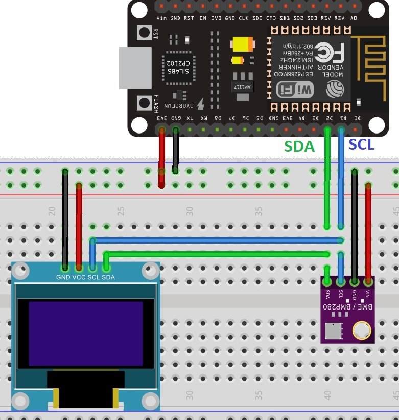
As you can see above, we have connected all the VCC terminals with a 3.3V power supply. The SCL terminals are connected with GPIO5 and the SDA terminals are connected with GPIO5. The grounds are also common.
MicroPython Code: Displaying BME280 readings on OLED Display
from machine import Pin, I2C        #importing relevant modules & classes
from time import sleep
import BME280        #importing BME280 library
import ssd1306       #importing OLED library

i2c = I2C(scl=Pin(22), sda=Pin(21), freq=10000)     #initializing the I2C method for ESP32
#i2c = I2C(scl=Pin(5), sda=Pin(4), freq=10000)       #initializing the I2C method for ESP8266
oled=ssd1306.SSD1306_I2C(128,64,i2c)

while True:
  oled.fill(0)
  bme = BME280.BME280(i2c=i2c)          #BME280 object created
  temperature = str(bme.temperature)          #reading the value of temperature
  humidity = str(bme.humidity)                      #reading the value of humidity
  pressure = str(bme.pressure)                   #reading the value of pressure

  print('Temperature is: ', temperature)    #printing BME280 values
  print('Humidity is: ', humidity)
  print('Pressure is: ', pressure)
  oled.text("Temp. "+temperature, 0, 0)
  oled.text("PA "+pressure, 0, 20)
  oled.text("Hum. "+humidity, 0,40)
  oled.show()                          #display pix
  sleep(10)           #delay of 10s
How does the code work?
In the section, we only explained the Micropython code part which is used to display sensor values on OLED. Because reset of the code is the same as we have used in previous sections to display sensor readings on the shell console.
Import SSD1306 OLED library.
import ssd1306 #importing OLED library
Create an instance of the SSD1306_I2C() method by giving it the name of oled. The first two arguments to SSD1306_I2C() are the size of the OLED, that is the number of columns and rows. A last argument is an object of I2C pins which we define with SoftI2C().
oled=ssd1306.SSD1306_I2C(128,64,i2c)Clears the OLED display with led.fill() routine.
oled.fill(0)Take BME280 sensor temperature, humidity, and pressure samples and convert them into string. Also,concatenate units of these values with strings.
bme = BME280.BME280(i2c=i2c)          #BME280 object created
temperature = str(bme.temperature)          #reading the value of temperature
humidity = str(bme.humidity)                      #reading the value of humidity
pressure = str(bme.pressure)                   #reading the value of pressure

print('Temperature is: ', temperature)    #printing BME280 values
print('Humidity is: ', humidity)
print('Pressure is: ', pressure)
Finally, display the text along with sensor readings on OLED.
oled.text("Temp. "+temperature, 0, 0)
oled.text("PA "+pressure, 0, 20)
oled.text("Hum. "+humidity, 0,40)
At the end, call the show() method on oled method for changes to show on OLED.
oled.show()                          #display pix
sleep(10)           #delay of 10s
Demonstration
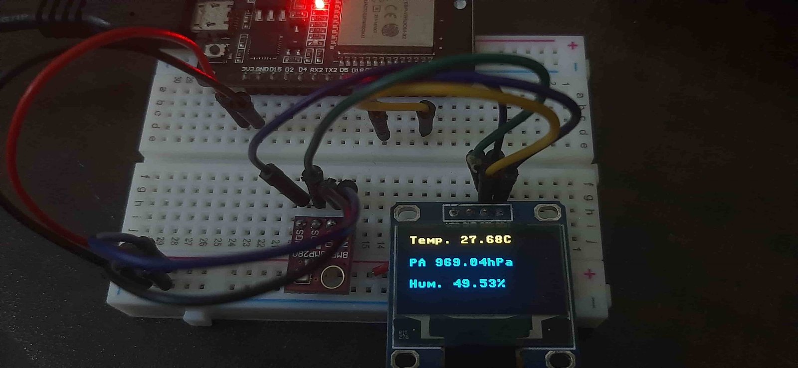
Upload the above code as a main.py file along with bme280.py and ssd1306.py to ESP32 or ESP8266. After that press the reset button on your ESP board. You will see BME280 temperature, pressure, and humidity values on the OLED display as follows:
Video Demo:
If you want to display BME280 sensor values on a web page, you can read our web server tutorial with BME280 and ESP32/ESP8266 using MicroPython:
If you found this tutorial interesting, you can read other popular sensors interfacing with ESP32 and ESP8266 using MicroPython firmware:
More MicroPython tutorials:
- MicroPython: BME680 Web Server with ESP32 and ESP8266
- ESP32/ESP8266 MicroPython Web Server – Control Outputs
- MicroPython: DHT11/DHT22 Web Server with ESP32/ESP8266
- MicroPython: Timers with ESP32 and ESP8266
- ESP32/ESP8266 ADC with MicroPython
- MicroPython: Interrupts with ESP32 and ESP8266
- Push Button with ESP32 and ESP8266 using MicroPython
- MicroPython: PWM with ESP32 and ESP8266
hello. im trying to use the tutorial on my esp32 and get the error
Traceback (most recent call last):
File “”, line 11, in
File “BME280.py”, line 90, in __init__
OSError: [Errno 19] ENODEV
can you help me?
thank you.
Yes. The i2c is not found. Check wiring.
Everything up and running but I get 0 percent for humidity…any thoughts?
thanks