This tutorial shows how to interface HC-SR04 or HY-SR05 Ultrasonic sensors with ESP32 for contactless distance measurement. First, we will learn to interface HC-SR04 with ESP32. After that, we will see example codes with or without the Ultrasonic sensor Arduino library. Firstly, we will see an example to control an LED with ESP32 and an Ultrasonic sensor. After that, we will see an example to display distance (cm) measurement on OLED.
We have a similar guide for Arduino:
Recommended Components
The following components are used in this project or are helpful for building it with the ESP32.
| Component | How it’s used in this project | Buy on Amazon |
|---|---|---|
| ESP32 Development Board (DevKit V1) | The main controller that runs the project code and connects to the components. | Check Price |
| Micro USB Cable | Connects the ESP32 to your computer for programming and power. | Check Price |
| Breadboard | Lets you build the circuit and wire up parts without soldering. | Check Price |
| Jumper Wires | Make the connections between the ESP32 and the components on the breadboard. | Check Price |
| HC-SR04 ultrasonic sensor | Measures distance that the ESP32 reads and displays. | Check Price |
| 0.96″ SSD1306 OLED Display | Shows the sensor readings locally on an I2C OLED screen. | Check Price |
As an Amazon Associate we earn from qualifying purchases. Prices and availability are accurate as of the date/time indicated and are subject to change.
HC-SR04 Ultrasonic Sensor Introduction
To interface the HC-SR04 ultrasonic sensor with ESP32, we should know the functionality of each pin of the ultrasonic sensor. By knowing the functionality of input and output pins, we will be able to identify which GPIO pins of ESP32 should be used to interface with HC-SR04.
HC-SR04 Pinout
The figure given below shows the pin configuration of an ultrasonic sensor. It consists of four pins namely; Vcc, Ground, Trigger, and Echo pin.
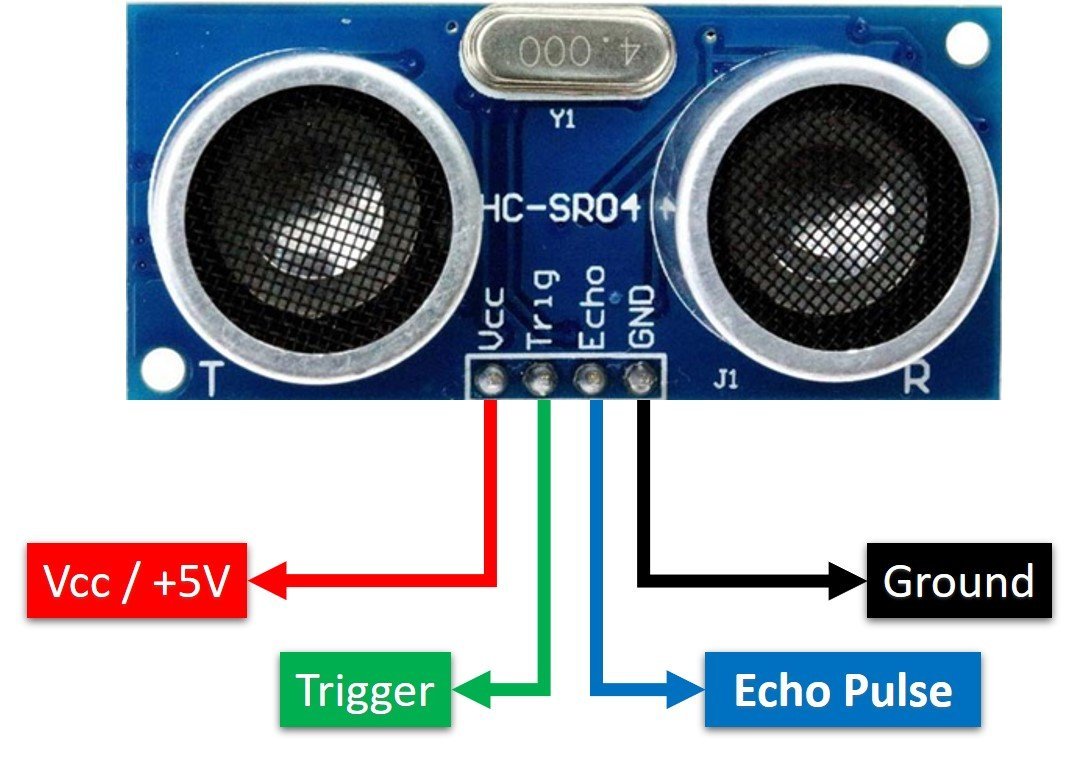
Vcc and Ground are used to power sensor. We should supply 5 volts to the Vcc pin and connect the GND pin with the ground terminal of the power supply.
Trigger: It is an input pin. Trigger pin is used to initiate the ultrasonic sensor to start distance measurement or distance ranging. When users want to get distance measurements from the sensor, we apply a 10µs pulse to this pin.
Echo: This is a pulse output pin. The echo pin produces a pulse as an output. The width of pulse or on-time of the pulse depends on the distance between the ultrasonic sensor and the obstacle which is placed in front of the HC-SR04 sensor. In idle conditions, this pin remains at an active low level.
Further details on ultrasonic sensor working are provided in the next section.
How HC-SR04 Sensor Works?
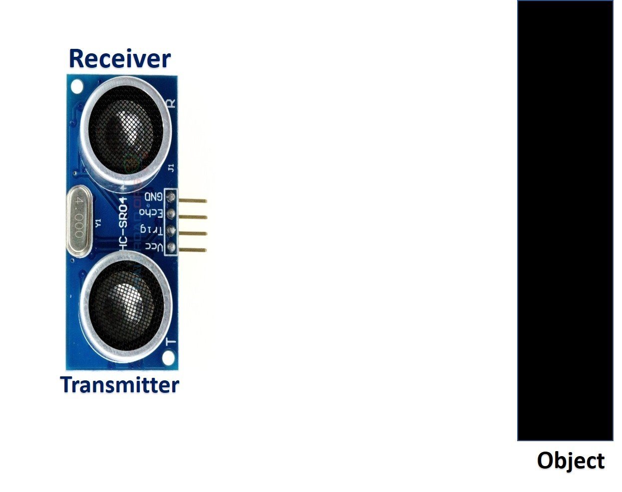
HC-SR04 ultrasonic sensor measures distance by using inaudible ultrasonic sound waves of 40KHz frequency. Like sound waves, ultrasonic waves travel through the air and if there is any obstacle in front of them, they reflect according to their angle of incidence. Moreover, if an object is placed parallel to an ultrasonic transmitter, ultrasonic waves reflect exactly at an angle of 180 degrees. Therefore, for distance measurement with HC-SR05 sensor, we place the object under test exactly in a parallel position with an ultrasonic sensor as shown in the figure below.
HC-SR05 ultrasonic sensor consists of two basic modules such as ultrasonic transmitter and ultrasonic receiver module. The transmitter circuit converts an electrical signal into a 40KHz burst of 8 sonar wave pulses. The input electrical signal to the transmitter circuit is 10µs pulse input to the trigger pin of the HC-SR04 sensor. As we mentioned earlier, we apply this trigger input signal through ESP32 or any microcontroller. On the other hand, the ultrasonic receiver circuit listens to these ultrasonic waves which are produced by the transmitter circuit.
Measure HC-SR04 Echo Pulse Time with ESP32
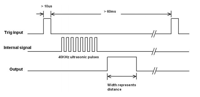
- To start ranging with HC-SR04, first, we apply 10µs pulse to the trigger pin of the HC-SR04 sensor from the ESP32 digital output pin.
- As soon as 10µs input trigger signal becomes active low, the transmitter circuit produces a burst of 8 ultrasonic sonar pulses. At the same time, the Echo pin also makes a transition from a logic low level to a logic high level.
- When the Echo pin goes high, We start to measure time with the ESP32 duration measurement function.
- These waves travel through the air and if there is any object placed in parallel to the sensor, these waves reflect back after a collision with the object.
- As soon as the ultrasonic waves received by the receiver circuit after striking with an object, the echo pin goes low. ESP32 detects this transition of echo output signal from active high to an active low level and stops the measurement.
In short, by measuring the on-time of the Echo output pulse signal, we can measure the distance. The following figure illustrates the echo output signal with respect input trigger signal and 8 sonar pulses.
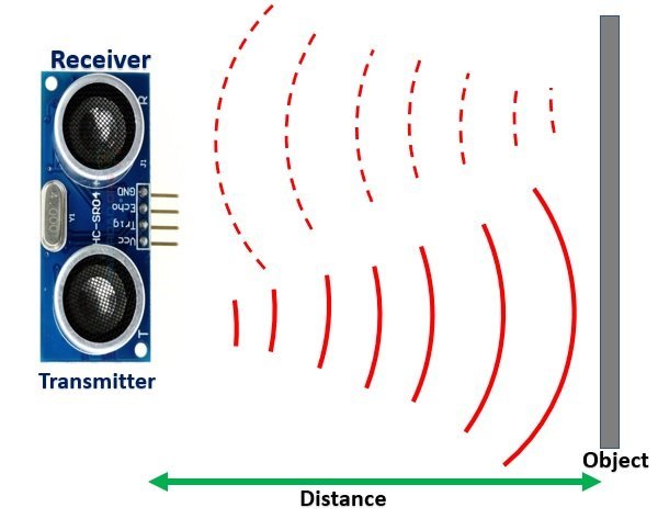
The duration for which the echo output signal remains high depends on the distance between the ultrasonic sensor and the object which we place in front of the sensor. Higher is the distance, the higher the time sonar waves will take to reach back to the ultrasonic receiver circuit. Because ultrasonic waves travel through the air with the speed of sound and speed remains constant.
How to Convert Time Duration into Distance
In the next section, we will see how to measure pulse duration using ESP32. Let’s assume that we have measured the output pulse on time (t) with ESP32. Now the question is how to convert this measured time into distance.
Well, this is the most obvious part of this tutorial. In high school, we all study a well-known distance-time equation that is S = vt. We can convert the pulse duration (t) into the distance (S) using this equation.
Distance (S) = Speed (v) * t //distance in meters
Here v is the speed of ultrasonic waves in air. The speed of ultrasonic waves in air is equal to the speed of sound which is 340 m/s (meter per second).
The above equation will give distance output in units of meter. But, if you want the distance in centimeter units, multiply 340 with 100. Hence, the above equation becomes:
S = 34000 * t // distance in cm
The time given in the above formula should also be divided by two. Because ultrasonic waves travel from the transmitter to the obstacle and then reflect back to the receiver circuit by traveling the same distance. We want to find the distance between HC-SR04 and the object only. Therefore, the formula to calculate distance becomes :
S = 17000 * t // distance in cm
How to Interface HC-SR04 Ultrasonic sensor with ESP32
Until now we have seen the working of the ultrasonic sensor and the pin details. Now we know that to interface an HC-SR04 sensor with ESP32, we need four pins out of which two are power supply pins and two are digital input output pins. One GPIO pin of the ESP32 will be used as a digital output pin to provide a trigger signal to the ultrasonic sensor. Similarly, one GPIO pin will be used as a digital input pin to capture echo output signal of output sensor.
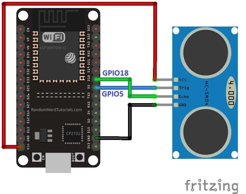
Now make the connection of the ESP32 with the HC-SR04 sensor according to this connection diagram. In this schematic diagram, we use the GPIO5 pin of ESP32 to provide a trigger signal and GPIO18 to capture the echo output pulse.
| HC-SR04 | ESP32 |
|---|---|
| Vcc | Vin |
| GND | GND |
| Trigger | GPIO5 |
| Echo | GPIO18 |
Arduino Code for Ultrasonic Sensor with LED
In this example code, we will control an LED based on measured distance value. ESP32 has an onboard LED that is connected with the GPIO2 pin. This code takes the distance measurement and if the measured distance value is less than 10cm, LED will turn on. Otherwise LED remains off.
/*
* Ultrasonic Sensor HC-SR04 interfacing with  ESP32
*
* by microcontrollerslab.com
*/

/* Define the names for ESP32 pin for HC-SR04*/
#define trigger_pin 5
#define Echo_pin 18
#define LED 2

/* two variables to store duraion and distance value */
long duration;
int distance;

/* configure D9 and D11 as digital input and output respectively */
void setup() {
pinMode(trigger_pin, OUTPUT); // configure the trigger_pin(D9) as an Output
pinMode(LED, OUTPUT); // Set the LED (D13) pin as a digital output
pinMode(Echo_pin, INPUT); // configure the Echo_pin(D11) as an Input
Serial.begin(9600); // Enable the serial with 9600 baud rate
}

void loop() {

digitalWrite(trigger_pin, LOW); //set trigger signal low for 2us
delayMicroseconds(2);

/*send 10 microsecond pulse to trigger pin of HC-SR04 */
digitalWrite(trigger_pin, HIGH);  // make trigger pin active high
delayMicroseconds(10);            // wait for 10 microseconds
digitalWrite(trigger_pin, LOW);   // make trigger pin active low

/*Measure the Echo output signal duration or pulss width */
duration = pulseIn(Echo_pin, HIGH); // save time duration value in "duration variable
distance= duration*0.034/2; //Convert pulse duration into distance

/* if distance greater than 10cm, turn on LED */
if ( distance < 10)
digitalWrite(LED, HIGH);
else
digitalWrite(LED, LOW);
// print measured distance value on Arduino serial monitor
Serial.print("Distance: ");
Serial.print(distance);
Serial.println(" cm");
delay(1000);
}
How Code Works?
First, define the names of ESP32 pins using #define preprocessor directives. This defines that GPIO5 and GPIO18 pins of ESP32 are used to control trigger and echo pins of the HC-SR04 sensor. Similarly, the GPIO2 pin is assigned the name LED. Hence, through the program, we will use these symbolic names instead of pin numbers.
#define trigger_pin 5
#define Echo_pin 18
#define LED 2
These two variables are declared to store duration and distance values.
long duration;
int distance;
Inside Setup()
In the ESP32 program, we perform configuration and initialization settings inside the setup() function. In this code, we initialize trigger_pin and LED pins as digital output pins and Echo_pin as a digital input pin. Also, enable serial communication to send distance measurement data to the ESP32 serial monitor.
pinMode(trigger_pin, OUTPUT); // configure the trigger_pin(D9) as an Output
pinMode(LED, OUTPUT); // Set the LED (D13) pin as a digital output
pinMode(Echo_pin, INPUT); // configure the Echo_pin(D11) as an Input
Serial.begin(9600); // Enable the serial with 9600 baud rate
If you don’t know to configure GPIO pins of ESP32 as digital input or output pins, you can refer to these tutorials:
Main loop()
Code written inside the loop() function executes repeatedly. Hence, we perform distance measurement or other useful functions inside this main loop() function.
As you know that to enable the ranging of data from the HC-SR04 sensor, we provide a 10µs pulse to the trigger pin. Therefore, This segment of code provides a 10µs pulse to trigger pin. It will initiate the distance sample taking process.
digitalWrite(trigger_pin, LOW); //set trigger signal low for 2us
delayMicroseconds(2);

/*send 10 microsecond pulse to trigger pin of HC-SR04 */
digitalWrite(trigger_pin, HIGH);  // make trigger pin active high
delayMicroseconds(10);            // wait for 10 microseconds
digitalWrite(trigger_pin, LOW);   // make trigger pin active low
As soon as we apply a 10µs pulse to the ultrasonic sensor, in response, it produces 40KHz sonar waves and raised the Echo output signal to an active high state. The echo output signal remains active high until these sonar waves reflect back to the ultrasonic transmitter. As soon as, receiver circuit received these waves, the echo output signal goes to an active low level. Hence, this line measures the timer for which the output signal remains in an active high state.
duration = pulseIn(Echo_pin, HIGH); // save time duration value in "duration variableIn Arduino IDE, the pulseIn() function is used to measure the pulse duration and it returns the time duration output in microseconds. But the formula of the distance-time relationship that we derived above works if both speed and time have the same units in terms of time such as seconds, microseconds, or milliseconds. But in this equation, speed unit is centimeters per second.
S = 17000 * t // distance in cm
To convert speed into centimeter per microsecond, divide this equation with 10^-6. Now units of speed and time both are compatible with each other.
S = 0.017* t // distance in cm
Finally, this line converts the pulse duration into the distance (cm).
distance= duration*0.034/2;If-else conditional block checks either measured distance is less than or greater than 10CM. If it is greater than 10, turn on an LED. Otherwise, LED remains turn off.
if ( distance < 10)
digitalWrite(LED, HIGH);
else
digitalWrite(LED, LOW);
In the end, serial.print() function prints the measured distance on Arduino serial monitor.
// print measured distance value on Arduino serial monitor
Serial.print("Distance: ");
Serial.println(distance);
Demonstration
To see the demonstration of the above code, upload the code to ESP32. Before uploading the code, make sure to select the ESP32 board from Tools > Board.

Also select the correct COM port to which the ESP32 board is connected from Tools > Port.

Once the code is uploaded to ESP32, you will be able to see distance in centimeter unit on the serial monitor:
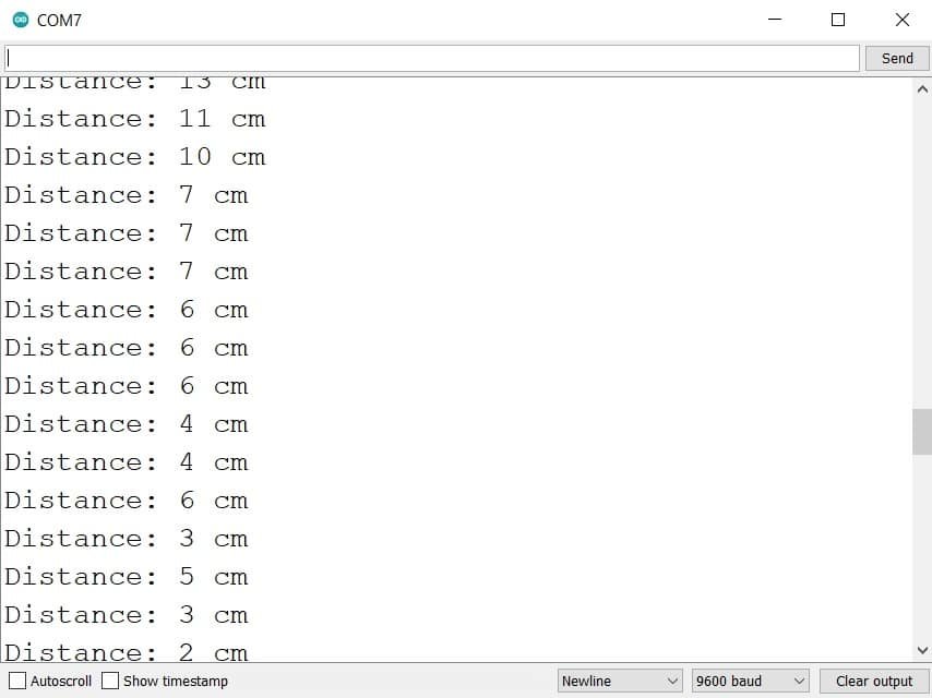
Also, you will observe that the onboard LED of ESP32 will turn on if the distance is less than 10CM.
Displaying HC-SR04 Sensor values on OLED Display with ESP32
In this section, we will see how to display HC-SR04 sensor distance on a 0.96 SSD1306 OLED display using ESP32 and Arduino IDE.
You can read this in-depth guide on OLED interfacing with ESP32:
OLED Display Interfacing with ESP32 – Display Text, Draw shapes and Images
Installing OLED Libraries in Arduino IDE
To use the OLED display in our project, we have to install the Adafruit SSD1306 library and Adafruit GFX library in Arduino IDE. Follow the steps below to successfully install them.
Open Arduino IDE and click on Sketch > Library > Manage Libraries. Type ‘SSD1306’ in the search tab and install the Adafruit SSD1306 OLED library.

We will also require the Adafruit GFX library which is a dependency for SSD1306. Type ‘Adafruit GFX’ in the search tab and install it as well.
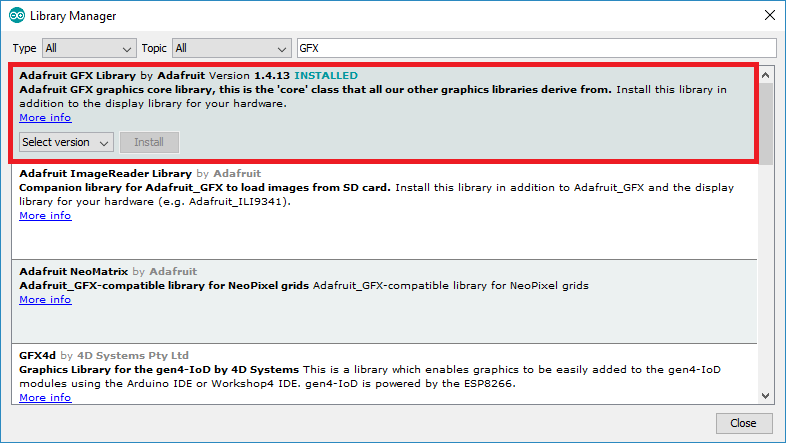
After installing the libraries, restart your IDE.
ESP32 I2C Pins
The I2C pins stated above are set in default. If we want to change the GPIO pins we have to set them in code. The diagram below shows the pinout for the ESP32.
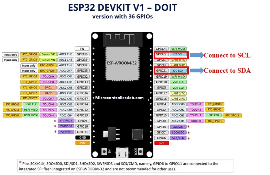
Note: If we use other GPIO pins of ESP32 for I2C communication, we can define other pins inside our Arduino sketch. We don’t have to use default I2C pins.
You can learn more about I2C communication here:
I2C Communication Introduction
Connection Diagram– OLED with ESP32 and HC-SR04
Required Components
- ESP32
- HC-SR04 ultrasonic sensor
- 0.96-inch SSD 1306 OLED Display
- 4.7k ohm resistor
- Breadboard
- Connecting Wires
Assemble the circuit as shown in the schematic diagram below:
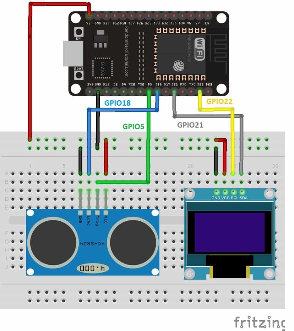
As you can see above, we have connected all the VCC terminals of OLED and HC-SR04 with a Vin pin of ESP32. The data trigger and echo pins of the ultrasonic sensor are connected with the GPIO5 and GPIO18 pins of ESP32 board, respectively.
The SCL terminal of the OLED is connected with GPIO22 and the SDA terminal of the OLED is connected with the GPIO21 pin of ESP32. The grounds of all three devices are common.
| ESP32 board | SSD1306 OLED Display | HC-SR04 |
|---|---|---|
| Vin | VCC | VCC |
| GPIO21(I2C SDA) | SDA | |
| GPIO22(I2C SCL) | SCL | |
| GPIO5 | Trigger | |
| GPIO18 | Echo | |
| GND | GND | GND |
Arduino Sketch (Displaying Temperature Readings on OLED Display)
Open your Arduino IDE and go to File > New. A new file will open. Copy the code given below in that file and save it. This sketch will read the sensor data from the HC-SR05 ultrasonic sensor and display it on the Serial Monitor as well as on the OLED.
/*
* Ultrasonic Sensor HC-SR04 interfacing with ESP32 and OLED
*
* by microcontrollerslab.com
*/
#include <Adafruit_GFX.h>
#include <Adafruit_SSD1306.h>
/* Define the names for ESP32 pin for HC-SR04*/
#define trigger_pin 5
#define Echo_pin 12

#define SOUND_VELOCITY 0.034
#define CM_TO_INCH 0.393701

/* two variables to store duraion and distance value */
long duration;
int distance;

Adafruit_SSD1306 display = Adafruit_SSD1306(128, 64, &Wire, -1);
/* configure D9 and D11 as digital input and output respectively */
void setup() {
pinMode(trigger_pin, OUTPUT); // configure the trigger_pin(D9) as an Output
pinMode(Echo_pin, INPUT); // configure the Echo_pin(D11) as an Input
Serial.begin(9600); // Enable the serial with 9600 baud rate
if(!display.begin(SSD1306_SWITCHCAPVCC, 0x3C)) {
  Serial.println(F("SSD1306 allocation failed"));
  for(;;);
}
  delay(1000);
display.clearDisplay();
display.setTextColor(WHITE);
}

void loop() {

delay(1000);
display.setCursor(0,0);
display.setTextSize(1);
display.clearDisplay();

digitalWrite(trigger_pin, LOW); //set trigger signal low for 2us
delayMicroseconds(2);

/*send 10 microsecond pulse to trigger pin of HC-SR04 */
digitalWrite(trigger_pin, HIGH);  // make trigger pin active high
delayMicroseconds(10);            // wait for 10 microseconds
digitalWrite(trigger_pin, LOW);   // make trigger pin active low

/*Measure the Echo output signal duration or pulss width */
duration = pulseIn(Echo_pin, HIGH); // save time duration value in "duration variable
distance = duration * 0.034/2;
Serial.print("Distance: ");
Serial.println(distance);


  display.setTextSize(1);
  display.setCursor(0,0);
  display.print("Distance: ");
  display.setTextSize(2);
  display.setCursor(0,10);
  display.print(distance);
  display.setTextSize(2);
  display.print("cm");

  Serial.println();
  display.display();
  delay(500);
}
How the Code Works?
The maximum part of the above code is the same as we discussed in the last example except for the OLED part.
Including Libraries
Firstly, we will include all the following libraries which are required for this project. Adafruit_GFX.h and Adafruit_SSD1306.h will allow us to communicate with OLED through the I2C protocol. Whereas the library is required for the proper functionality of the OLED display.
#include <Adafruit_GFX.h>
#include <Adafruit_SSD1306.h>
Defining HC-SR04 Ultrasonic sensor parameters
Secondly, we will create a variable to define the GPIO pin through which the sensor’s echo and trigger pins are connected. We have used GPIO5 and GPIO18 in this example.
/* Define the names for ESP32 pins for HC-SR04*/
#define trigger_pin 5
#define Echo_pin 18
Defining OLED Display
We will initialize the display by creating an object and specifying the width, height, I2C instance (&Wire), and -1 as parameters inside Adafruit_SSD1306. -1 specifies that the OLED display which we are using does not have a RESET pin. If you are using the RESET pin then specify the GPIO through which you are connecting it with your development board.
Adafruit_SSD1306 display = Adafruit_SSD1306(128, 64, &Wire, -1);setup() function
Inside the setup() function, we will open a serial connection at a baud rate of 9600. Moreover, we will also initialize the OLED display. Make sure you specify the correct address of your display. In our case, it is 0X3D.
Serial.begin(9600);
  if(!display.begin(SSD1306_SWITCHCAPVCC, 0x3D)) {
  Serial.println(F("SSD1306 allocation failed"));
  for(;;);
Your OLED can also have 0x3C and you can try it also if 0x3D does not work for you. The following lines of code will clear the display and set the text color to white.
display.clearDisplay();
display.setTextColor(WHITE);
loop() function
Inside the loop() function, we will display the temperature readings on the OLED display and the Serial Monitor.
We will use the setCursor() function to denote the x and the y axis position from where the text should start. We have passed (0,0) as the parameter hence the text starts from the upper left corner. THe clearDisplay() function will wipe off the previous readings from the display after each loop() so that new ones can be printed.
display.setTextSize(1);
display.setCursor(0,0);
display.print("Distance: ");
display.setTextSize(2);
display.setCursor(0,10);
display.print(distance);
display.setTextSize(2);
display.print("cm");

Serial.println();

display.display();
delay(500);
Demonstration
To see the demonstration of the above code, upload the code to ESP32. Before uploading the code, make sure to select the ESP32 board from Tools > Board and also select the correct COM port to which the ESP board is connected from Tools > Port.
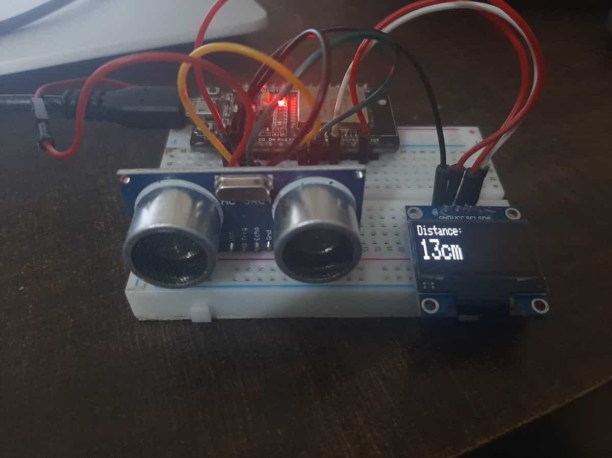
Once the code is uploaded to ESP32, open the serial monitor of Arduino IDE and set the baud rate to 9600. Finally, we can see the HC-SR04 measured distance readings on the Arduino serial monitor and on the OLED display as shown below:

Video Demo:
Applications of Ultrasonic sensor HC-SR04
There are many applications of ultrasonic sensors from domestic use to industrial use. But some of them are given below :
- Obstacle avoidance robot
- Robotics
- Object detection
- Distance measurement
- Liquid level monitoring system
- Height measurement
- Agriculture
- Vehicle collision protection
Related Tutorials:
Hi,
I have a question about the sensor. So you connect 5 V to the sensor but use 3.3 V GPIO pins to communicate. Isn’t this dangerous to fry the pins of your microcontroller as the voltages don’t match? Shouldn’t this setup use a logic shifter to be more secure?
Kind greetings
most of the pins of ESP32 are 5V tolerant. But you can use voltage level shifter to be on safe side.