In this tutorial, we will learn to use the MPU-6050 MEMS module with ESP32 and ESP8266 to measure accelerometer, gyroscope, and temperature values using MicroPython firmware. Firstly, we will see an introduction of MPU6050 such as pinout diagram, pin configuration. Secondly, we will see how to upload the MPU-6050 MicroPython library to ESP boards using uPyCraft IDE or Thonny IDE. In the end, we will see how to get an accelerometer, gyroscope, and temperature readings from the MPU-6050 module with ESP32 and ESP8266.
Recommended Components
The following components are used in this project or are helpful for getting started with MicroPython on ESP32 and ESP8266.
| Component | How it’s used in this project | Buy on Amazon |
|---|---|---|
| ESP32 Development Board (DevKit V1) | The ESP32 board flashed with MicroPython firmware. | Check Price |
| ESP8266 NodeMCU (ESP-12E) | The ESP8266 NodeMCU running the same MicroPython code. | Check Price |
| Micro USB Cable | Programs and powers the board from your PC. | Check Price |
| MPU6050 Module | Reads accelerometer, gyroscope, and temperature values over I2C. | Check Price |
| Breadboard | Holds the module and board for wiring. | Check Price |
| Jumper Wires | Connect the module to the I2C pins. | Check Price |
As an Amazon Associate we earn from qualifying purchases. Prices and availability are accurate as of the date/time indicated and are subject to change.
MPU6050 Sensor Module Introduction
The MPU-6050 sensor module is a MEMS( Micro Electro-Mechanical System) module which contains an integrated circuit MPU-6050 IC. This chips contains three axis gyroscope, three axis accelerometer and digital motion control processor within a single IC package. On top of that, it also contains an integrated temperature sensor. All these sensors are manufactured on the same die of MPU6050. We can use this module for velocity, acceleration, orientation, displacement and other motion related parameters measurement. Now-a-days all modern smartphones come with a built-in inertial motion sensor. MPU-6050 also belongs to one of these categories of sensors. This sensor provides a complete solution for any six axis motion tracking system.

One of the most important features of MPU-6050 MEMS sensors is that it contains a powerful and high processing power digital motion processor (DMP). DMP performs all complex calculations internally before letting the users read data from the sensor on the I2C port. That means we do not have to perform high power calculations on the microcontroller after reading data from the MPU6050 chip.
I2C Output Interface
As discussed earlier, MPU6050 provides output data on an I2C bus. Therefore, we can use a 12C bus interface of MPU6050 to transfer a 3-axis accelerometer and 3-axis gyroscope values to ESP32/ESP8266. In other words, we can use any microcontroller which has an I2C port to read sensors’ output data. There is a specific dedicated address assigned to each parameter value in the MPU6050 I2C interface. We can use these addresses to get specific values from a sensor such as acceleration, gyro, and temperature.
One of the advantages of using the I2C interface of this sensor is that we can interface multiple MPU5060 modules with a single microcontroller.
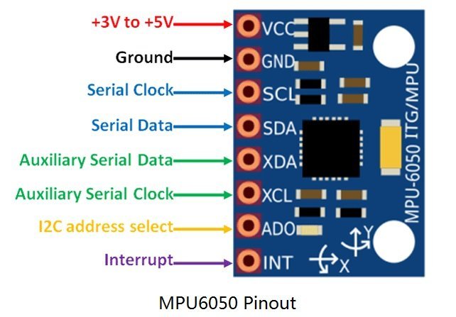
MPU6050 Pinout
The MPU6050 chip consists of 24 pins. But only 8 pins are exposed on the pinout of the module. This MEMS sensor module consists of 8 pins and these pins are used for different configurations and used to read data from the sensor.
- First one is a VCC pin that is used to power the sensor and 3 to 5 volts dc voltages are applied to power on this sensor. But usually, a 5V power source is provided directly from a microcontroller.
- The second [pin is a GND pin which is connected to the source ground and ground pin of a microcontroller.
- Pin number three is a SCL (serial clock) pin which is connected to a microcontroller SCL pin to which we want to interface MPU6050 sensor. SCL is a clock pulse pin used in I2C communication. The clock source is provided by the master device which is a microcontroller in our case.
- Fourth pin is a SDA (serial data) pin which is used to transfer data to a microcontroller. We connect SDA pin of MPU6050 with a SDA pin of a microcontroller
- Fifth one is a XDA (Auxiliary Serial Data) pin which is used to connect external I2C modules with MPU6050 such as magnetometer. But the use of this pin is completely optional.
- Sixth one is a XCL (Auxiliary clock) pin which is also connected to another 12C interface sensor to enable its pin from this sensor module.
- AD0 (Pin7) : AD0 (Address select pin) which is a 12C slave address select pin.For example, if we use more than one MPU6050 modules with a single microcontroller, this pin is used to vary the slave address for each MEMS sensor. By doing so, each MEMS sensor can be easily distinguished on an I2C bus with its unique address.
- INT(Pin8) : The INT (interrupt) pin which is an interrupt digital output pin and used to give indication to a microcontroller that the data is available to read from a MPU6050 sensor module.
The following picture shows the pinout diagram of MPU6050 MEMS module:
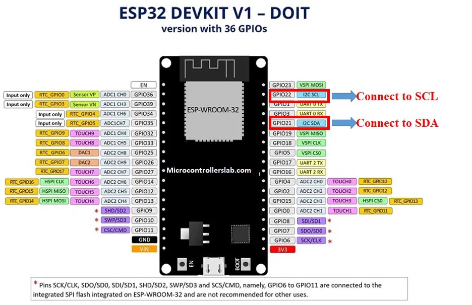
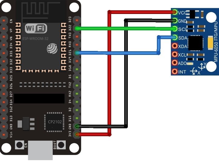
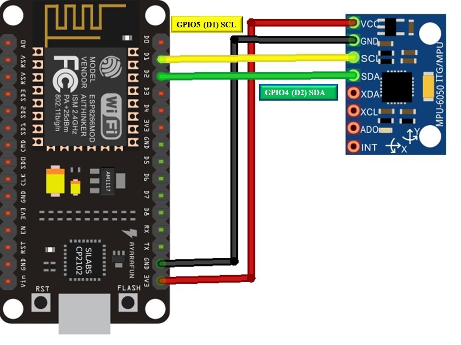
Interface MPU-6050 with ESP32 and ESP8266
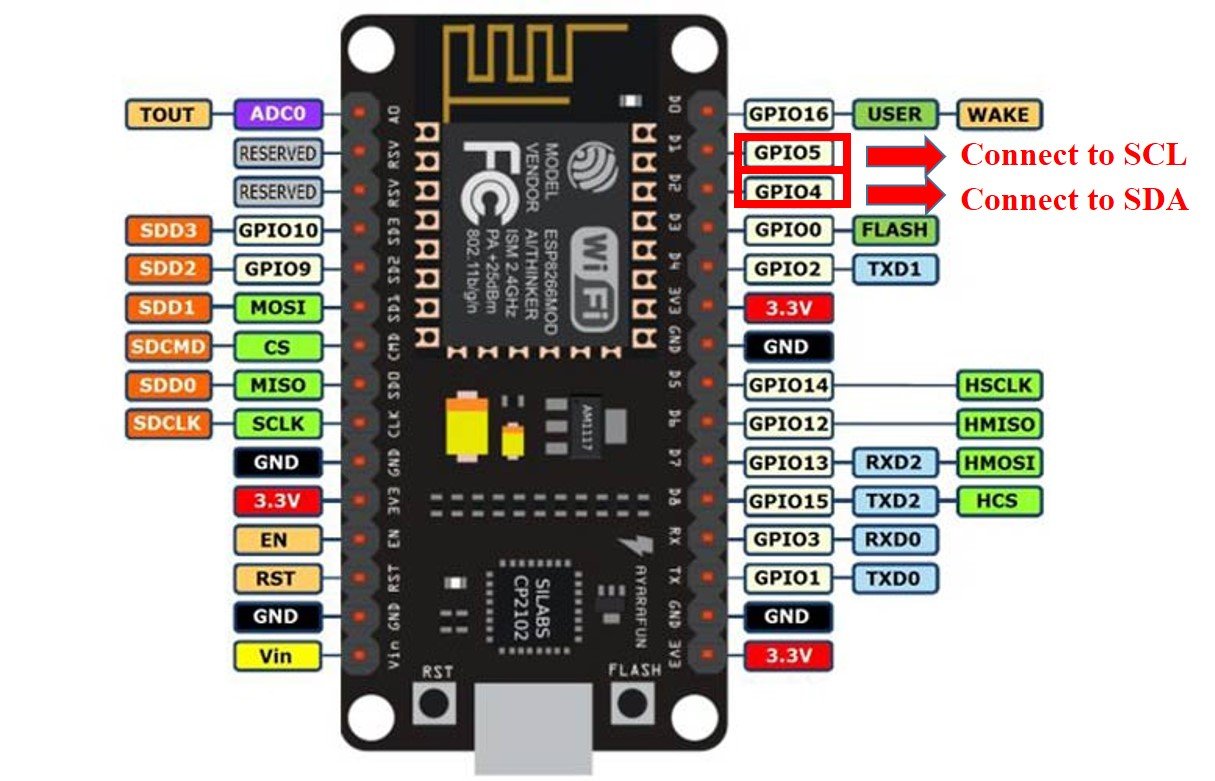
As you see, the MPU6050 has 8 terminals but in order to connect with ESP32 and ESP8266 NodeMCU, we will only require the first four pins highlighted in yellow. These are VCC, GND, SCL, and SDA. The table shows the connections between the two modules.
| ESP32 | ESP8266 | MPU-6050 |
|---|---|---|
| VCC=3.3V | 3.3V | Vin |
| GPIO21(I2C SDA) | GPIO4 (D2) | SDA |
| GPIO22 (I2C SCL) | GPIO5 (D1) | SCL |
| GROUND | GROUND | GROUND |
The VCC pin is connected with the 3.3V from the ESP32/ESP8266 module to power up. Both the grounds of the two devices are connected in common. The SCL pin of MPU6050 is connected with the default SCL pin of ESP32/ESP8266. Likewise, the SDA pin is connected with the default SDA pin of ESP boards.
ESP32 I2C Pins
The I2C pins stated above are set in default. If we want to change the GPIO pins we have to set them in code. The diagrams below show the pinout for the ESP32 and Esp8266 respectively.
ESP8266 I2C Pins
The following figure shows the I2C pins of ESP8266 NodeMCU:
More information on ESP32 and ESP8266 pins is available here:
Components Required
We will need the following components to connect our ESP board with the MPU6050 sensor.
- ESP32/ESP8266
- MPU-6050 MEMS Module
- Connecting Wires
- Breadboard
Schematic Diagrams
Follow the schematic diagrams below for both the ESP modules and connect them accordingly. If you are using ESP32 for this project, connect the ESP32 device with MPU-6050 as shown in the schematic diagram below:
Similarly, if you are using ESP8266 NodeMCU for this project, connect the ESP8266 device with MPU-6050 as shown in the schematic diagram below:
MPU-6050 MicroPython Library
By default, MicroPython does not have an implementation of the MPU-6050 library. But, MicroPyhon provides I2C API of ESP32 and ESP8266 which can be used to read values from the MPU-6050 sensor. Fortunately, there is one library available which is developed by Adam Ježek and can be downloaded from this link.
Hence, download the following library and upload it to ESP32/ESP8266 board with the name of mpu6050.py.
import machine


class accel():
    def __init__(self, i2c, addr=0x68):
        self.iic = i2c
        self.addr = addr
        self.iic.start()
        self.iic.writeto(self.addr, bytearray([107, 0]))
        self.iic.stop()

    def get_raw_values(self):
        self.iic.start()
        a = self.iic.readfrom_mem(self.addr, 0x3B, 14)
        self.iic.stop()
        return a

    def get_ints(self):
        b = self.get_raw_values()
        c = []
        for i in b:
            c.append(i)
        return c

    def bytes_toint(self, firstbyte, secondbyte):
        if not firstbyte & 0x80:
            return firstbyte << 8 | secondbyte
        return - (((firstbyte ^ 255) << 8) | (secondbyte ^ 255) + 1)

    def get_values(self):
        raw_ints = self.get_raw_values()
        vals = {}
        vals["AcX"] = self.bytes_toint(raw_ints[0], raw_ints[1])
        vals["AcY"] = self.bytes_toint(raw_ints[2], raw_ints[3])
        vals["AcZ"] = self.bytes_toint(raw_ints[4], raw_ints[5])
        vals["Tmp"] = self.bytes_toint(raw_ints[6], raw_ints[7]) / 340.00 + 36.53
        vals["GyX"] = self.bytes_toint(raw_ints[8], raw_ints[9])
        vals["GyY"] = self.bytes_toint(raw_ints[10], raw_ints[11])
        vals["GyZ"] = self.bytes_toint(raw_ints[12], raw_ints[13])
        return vals  # returned in range of Int16
        # -32768 to 32767

    def val_test(self):  # ONLY FOR TESTING! Also, fast reading sometimes crashes IIC
        from time import sleep
        while 1:
            print(self.get_values())
sleep(0.05)Uploading MPU-6050 Library with uPyCraft IDE
Now, we will look at how to install the MPU-6050 library to be used in MicroPython. This step is required because MicroPython itself does not contain the sensor’s library. Follow the steps in order to successfully upload the library to ESP32/ESP8266 in uPyCraft IDE:
- First, in the Tools section, click on the NEW FILE button and open a file.

- Then replicate the following MPU-6050 library in that file.
- Name the file mpu6050.py and save it by choosing your desired directory.

- Now press the button DOWNLOAD AND RUN in the tools section.

You have now successfully uploaded the MPU-6050 library to ESP32/ESP8266 using uPyCraft IDE. After that, we can use the above library functions to read the accelerometer, gyroscope, and temperature values from the MPU-6050 sensor. You can use a similar procedure to upload files using Thonny IDE.
Uploading MPU-6050 Library in Thonny IDE
If you are using Thonny IDE , open a new file and copy the code as we did in uPyCraft IDE.
- Save the file as mpu6050.py
- In addition, head over to Device> Upload Current Script with Current Name
You have successfully uploaded the MPU-6050 library to ESP32/ESP8266 using Thonny IDE.
MicroPython MPU-6050: Getting Accelerometer, Gyroscope, and Temperature values
As we have already uploaded the MPU-6050 library to ESP32/ESP8266 boards. Now we can use the functions available in the MPU-6050 library to get sensor readings.
Let’s now look at an example to show the working of the sensor. We will connect our MPU-6050 sensor with the ESP module via the I2C protocol as shown above in the connection diagrams. We will see a MicroPython script code and after uploading it to our ESP boards, we will see readings of Accelerometer, Gyroscope, and Temperature printed on the MicroPython shell terminal.
MPU-6050 MicroPython Code
Now let’s look at the MicroPython script for MPU-6050 to get sensor readings. Copy the following code to the main.py file and upload the main.py file to ESP32/ESP8266. This microPython script reads Accelerometer, Gyroscope, and Temperature values from MPU-6050 over I2C lines and prints them on the MicroPython shell console.
from machine import I2C
from machine import Pin
from machine import sleep
import mpu6050
i2c = I2C(scl=Pin(22), sda=Pin(21))     #initializing the I2C method for ESP32
#i2c = I2C(scl=Pin(5), sda=Pin(4))       #initializing the I2C method for ESP8266
mpu= mpu6050.accel(i2c)
while True:
 mpu.get_values()
 print(mpu.get_values())
 sleep(500)
How the Code Works?
Importing Libraries
Firstly, we will be importing the Pin class and I2C class from the machine module. This is because we have to specify the pin for I2C communication. We also import the sleep module so that we will be able to add a delay of 10 seconds in between our readings. Also, import the MPU6050 library which we have previously uploaded to ESP32 or ESP8266.
from machine import I2C
from machine import Pin
from machine import sleep
import mpu6050
Defining ESP32/ESP8266 GPIO Pins for MPU-6050
Now, we initialize the I2C method by giving it three arguments. The first argument specifies the GPIO pin for SCL. This is given as GPIO22 for ESP32 and GPIO5 for ESP8266. The second parameter specifies the GPIO pin for the SDA. This is given as GPIO21 for ESP32 and GPIO4 for ESP8266. Keep in mind, these are the default I2C pins for SCL and SDA which we have used for both the ESP boards respectively.
i2c = I2C(scl=Pin(22), sda=Pin(21))     #initializing the I2C method for ESP32
#i2c = I2C(scl=Pin(5), sda=Pin(4))       #initializing the I2C method for
Now, create an object of accel() class from mpu6050 module with the name of “mpu”.
mpu= mpu6050.accel(i2c)
Inside the while loop, get the sensor reading with using an object “mpu” on get_values() function. After that print the values on micropython shell console.
mpu.get_values()
print(mpu.get_values())
sleep(500)
Demo
To test the MicroPython script for MPU-6050 with ESP32 and ESP8266, upload the main.py file to ESP32/ESP8266. After uploading the MicroPython script, click on Enable/Reset button of ESP32 or ESP8266:

You will see the Accelerometer, Gyroscope, and Temperature values on shell console:
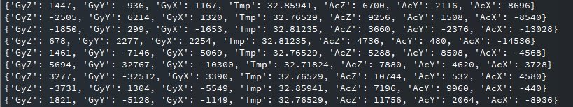
The values Accelerometer/Gyroscope are between -32768 to 32767.
More MicroPython tutorials:
- MicroPython ESP32/ESP8266: Send Sensor Readings via Email (IFTTT)
- ESP32/ESP8266 MicroPython Web Server – Control Outputs
- MicroPython: DHT11/DHT22 Web Server with ESP32/ESP8266
- MicroPython: Timers with ESP32 and ESP8266
- ESP32/ESP8266 ADC with MicroPython
- MicroPython: Interrupts with ESP32 and ESP8266
- Push Button with ESP32 and ESP8266 using MicroPython
- MicroPython: OpenWeatherMap API with ESP32/ESP8266 – Sensorless Weather Station
- MicroPython: PWM with ESP32 and ESP8266
Is it the same configuration with a PH sensor module?
I don’t think so.
why does it measure acceleration values even if it stands still? How can I fix this?
Please check your sensor or apply compensation to all readings.
how can you get the seperate values(tilt, x,y,z)?
Look at the mpu6050.py file you created. Find the function named get_values and it shows you how to read each value. Create your own functions in mpu6050.py to pull the specific values you want.
How get you get the seperate valeus(tilt, x,y,z) ?