In this tutorial, we will learn to interface HC-SR04 ultrasonic sensor with pic microcontrollers and how to measure distance with the HC-SR04 ultrasonic sensor? There are a variety of Pic microcontroller chips available. But the concepts, you will learn to interface the HC-SR04 ultrasonic sensor with any pic microcontroller remain the same. This sonar sensor has important and useful applications for embedded systems projects such as contactless range meter, contactless water level measurement, and sonar system. Before we proceed further with this tutorial, we recommend you to read about ultrasonic sensors and its working here:
Difference Between HC-SR04 and HY-SRF05
In this tutorial, we will be using HC-SR04 ultrasonic sensor but there is another version of this sensor which is HY-SRF05. Both sensors have the same electrical properties and can be used in replacement for each other except HY-SRF05 has one 1mm better precision than HC-SR04. But 1mm is not an issue when measuring distance in the units of cm and meter.
We will be using HC-SR04 for distance measurement. But the code works with the HY-SRF05 sensor also. PIC16F887 microcontroller will be used to read ultrasonic sensor output signals. Moreover, a 16×2 LCD is used to display the measured value of distance on an LCD.

HC-SR04 Ultrasonic sensor Introduction
This is a contactless measurement sensor. It can measure distance up to 2cm – 400cm. Its accuracy is about three millimeters which is very efficient in water level and depth measurement applications.
HC-SR04 Ultrasonic sensor Pinout
It consists of four pins. The following figure shows the pinout diagram.

| Pin Name | Function |
|---|---|
| Vcc | Connect 5 volt supply with this pin. |
| Trigger | Used to initiate distance ranging |
| Echo | Provides output pulse signal |
| Ground | Connect with ground terminal |
Working
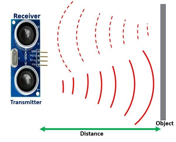
HC-SR04 ultrasonic sensor is consists of three main circuits. Description of each module is given below:

Transmitter module
When we want to measure distance with HC-SR04, we provide 10 microseconds pulse to the trigger pin of the sensor. In response, The transmitter circuit sends eight 40KHz ultrasonic sound wave pulses through the air. Hence, the transmitter circuit converts the electrical signal into a 40KHz burst of 8 pulses.
Receiver module
When an ultrasonic transmitter circuit completes transmission of 8 pulses. The echo pin goes high. The echo pin remains active high until the ultrasonic sound wave does not reflect back to the receiver circuit after striking the object Under test. As soon as the ultrasonic signal received by the receiver circuit after striking with an object, the echo pin goes low.
How to Measure Distance with HC-SR04 Ultrasonic Sensor
To measure distance with the HC-SR04 ultrasonic sensor, we provide a 10us trigger signal from the pic microcontroller to trigger pin of the sensor. The width of the trigger signal should be at least 10 microseconds. After that, an ultrasonic transmitter transmits a burst of 8 ultrasonic sound waves and makes the echo output pin active high.
If there is any obstacle in the front ultrasonic sensor and it is in the measurable range of sensor, the ultrasonic sound wave will reflect back to the HC-SR04 ultrasonic sensor.
When the receiver circuit receives the reflected signal ,the echo pin of the ultrasonic sensor goes low. Hence, a pulse is generated on the echo output pin.The time for which pulse remains high is equal to the total time taken by ultrasonic waves burst from sending and receiving back. That means the pulse duration is directly proportional to the distance.
In short, we can measure the distance by measuring the time for which the output echo pin remains in logic high state (pulse duration or pulse width).
We will use PIC16F887 microcontroller Timer module to measure the pulse duration.
How to convert Pulse Duration into Distance?
Let’s assume that we have measured the pulse duration using PIC16F887 timer. Now the question is how to convert the pulse duration (t) into distance. Well this is the easiest part of this tutorial. We can convert the pulse duration (t) into distance (S) using the famous equation of physics that is distance, time and speed equation.
Distance (S) = Speed (v) * t
Here v is the speed of ultrasonic waves in air. The speed of ultrasonic waves in air is equal to the speed of sound which is equal to 340 m/s (meter per second). Hence, the above equation becomes:
S = 340 * t // distance in meter
The above equation will give distance output in units of meter. But, if you want the distance in centimeter units, multiply 340 with 100. Also, divide it by 2 to get one path distance.
S = ( 34000 * t ) / 2 //distance in centimeter
Timing Diagram
The following figure shows the timing diagram of HC-SR04 input and output signals.
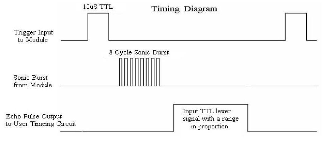
According to the above diagram, we will send a trigger pulse of at least 10 microseconds to sensor from Pic microcontroller. Afterward, the sensor will generate 8 cycles of a sonic burst. This electronics burst comes back after colliding with obstacles. The echo pin will produce a pulse of time taken by electronics burst to send and receive back.
To measure distance, we need to measure the time of the output pulse. After measuring the pulse time, we can easily calculate the distance by using the above given formula.
Ultrasonic sensor HC-SR04 interfacing with pic microcontroller
To measure output pulse duration we will use PIC16F877A timer.
We have previously posted an article on how to use timers of pic microcontroller, you can refer to this article:
To measure pulse duration with the PIC16887 timer, detect the rising edge of the pulse as soon as the rising edge is detected, enable the timer module and the timer will start counting. After that wait for the falling edge to occur. As soon as the falling edge is detected, disable the timer module. Now, save the content of the timer registers into a variable. This variable contains the number of ticks of the timer for the time duration of the output pulse.
To convert, these ticks into pulse duration, divide the number of ticks with the operating frequency of the timer module. Finally, this will give us the pulse duration. After that, multiply the pulse duration with the speed of light to get the measured distance from pulse duration.
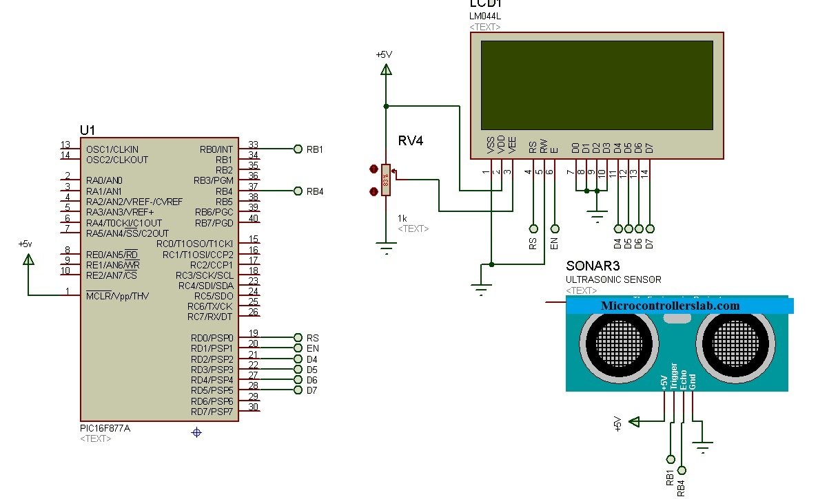
Schematic Diagram
The circuit given below shows the connections between Ultrasonic sensor HC-SR04, 16×2 LCD and Pic microcontroller. 16×2 LCD is used to display the measured distance value. If you do not know how to interface LCD with pic microcontroller. You may refer to this article:
HC-SR04 Code for PIC Microcontroller
Code is written using Mikro c for pic and it will work perfectly with pic16f877a and pic16f887 microcontroller. The crystal oscillator frequency is 8HMz.
// LCD module connections
sbit LCD_RS at RD0_bit;
sbit LCD_EN at RD6_bit;
sbit LCD_D4 at RD5_bit;
sbit LCD_D5 at RD4_bit;
sbit LCD_D6 at RD3_bit;
sbit LCD_D7 at RD2_bit;

sbit LCD_RS_Direction at TRISD0_bit;
sbit LCD_EN_Direction at TRISD6_bit;
sbit LCD_D4_Direction at TRISD5_bit;
sbit LCD_D5_Direction at TRISD4_bit;
sbit LCD_D6_Direction at TRISD3_bit;
sbit LCD_D7_Direction at TRISD2_bit;
// End LCD module connections

/* variables to store pulse duration and to display string on LCD 8 */
int time_taken;
char txt[7];
/* Main code to take distance measurement and initializations */
void main()
{

  TRISD=0x00;  /* initialize PORTD as digital ouput pin for LCD */
  Lcd_Init();   /* initialize LCD library functions */
  Lcd_Cmd(_LCD_CLEAR); /* Clear whatever is written on LCD */
  Lcd_Cmd(_LCD_CURSOR_OFF); /* Turn of LCD Cursor display */

  TRISB.B0 = 0; /* Set RB0 pin as a digital output pin */
  PORTB.B0 =0;  /* Initially sets the RB0 pin as activ low */

  TRISB.B4 = 0; /* Set RB4 pin as a digital input pin */
  PORTB.B4 =0;  /* Initially sets the RB4 pin as activ low */

  /* display "HC-SR04" on LCD */
  Lcd_Out(1,1,"HC-SR04");

  Delay_ms(2000); /* wait for one second */
  Lcd_Cmd(_LCD_CLEAR);  /* Clear text from LCD */

  T1CON = 0x10; /* Set timer1 prescaler value to 1:2 prscale and disable timer1 */

  while(1)
  {
     /* Initialize Timer1 register to zero */
     TMR1H = 0;
     TMR1L = 0;

     /* send 10us puls to triger pin of HC-SR04 from RB0 pin */
     PORTB.F0 = 1;
     Delay_us(10);
     PORTB.F0 = 0;

     while(!PORTB.F4);   /* wait till echo output signal goes high */
     T1CON.F0 = 1;    /* enable the Timer1 */
     while(PORTB.F4);  /* wait till echo output signal goes low */
     T1CON.F0 = 0; /*disable timer1 */

     time_taken= (TMR1L | (TMR1H<<8)); /*read the content of Timer1 registers */
     time_taken= (TMR1L | (TMR1H<<8))/58.82; /* convert duration into distance */

     /* This code block displays the measured distance value on LCD */
     if(time_taken>=0 && time_taken<=400)
     {
       IntToStr(time_taken,txt);
       Ltrim(txt);
       Lcd_Cmd(_LCD_CLEAR);
       Lcd_Out(1,1,"Distance = ");
       Lcd_Out(1,12,txt);
       Lcd_Out(1,15,"cm");
     }
    else
     {
       Lcd_Cmd(_LCD_CLEAR);
       Lcd_Out(1,1,"Out of Range");
     }
     Delay_ms(500);
  }
}
How Code Works?
First, we define the PIC16F877A microcontroller pins to which 16×2 LCD data and command pins are connected. In mikroC for pic compiler, LCD library provides all functions to print data on the screen. We just need to define the connection of LCD pins with pic microcontroller pins. These lines define the connection of PORTD pins RD5-RD2 with D4-D7 pins of LCD. Also, connect RS pin with RD0 and EN pin with RD6.
// LCD module connections
sbit LCD_RS at RD0_bit;
sbit LCD_EN at RD6_bit;
sbit LCD_D4 at RD5_bit;
sbit LCD_D5 at RD4_bit;
sbit LCD_D6 at RD3_bit;
sbit LCD_D7 at RD2_bit;

sbit LCD_RS_Direction at TRISD0_bit;
sbit LCD_EN_Direction at TRISD6_bit;
sbit LCD_D4_Direction at TRISD5_bit;
sbit LCD_D5_Direction at TRISD4_bit;
sbit LCD_D6_Direction at TRISD3_bit;
sbit LCD_D7_Direction at TRISD2_bit;
// End LCD module connections
Enable GPIO Pins
Initialize the LCD library and set the PORTD as a digital output pin. If you don’t know how to use GPIO Ports of pic microcontrollers, you can refer to this article:
 TRISD=0x00;  /* initialize PORTD as digital ouput pin for LCD */
 Lcd_Init();   /* initialize LCD library functions */
 Lcd_Cmd(_LCD_CLEAR); /* Clear whatever is written on LCD */
 Lcd_Cmd(_LCD_CURSOR_OFF); /* Turn of LCD Cursor display */
RB0 is used to provide 10us trigger signal to HC-SR04 trigger pin and RB4 pin is used to detect positive and negative edges of echo output signal of ultrasonic sensor. Therefore, we initialize the RB0 pin as a digital output pin and RB4 pin as a digital input pin.
TRISB.B0 = 0; /* Set RB0 pin as a digital output pin */
PORTB.B0 =0;  /* Initially sets the RB0 pin as activ low */


TRISB.B4 = 0; /* Set RB4 pin as a digital input pin */
PORTB.B4 =0;  /* Initially sets the RB4 pin as activ low */
Timer1 Configuration for Distance Measurement
PIC16F877A microcontroller has three timer modules such as Timer0, Timer1, and Timer2. We used Timer1 in this project. Timer1 is a 16-bit timer and it can be used either in timer or counter mode. It consists of two 8-bit registers namely; TMR1H, TMR1L. TMR1H holds the most significant 8-bits and TMR1L holds the least significant 8-bits. Hence, the Timer1 can count from 0x0000 to 0xFFFF.
Set Timer1 Mode
In this project, we used Timer1 in timer mode. Because in timer mode, the timer register values increments on every instruction cycle. Therefore, we can measure the time from timer register values.
T1CON register is used to configure Timer1 either as a timer or counter. The mode of the timer is selected with the TMR1CS bit1 of the T1CON register. Setting TMR1CS bit to 0 enables the timer mode, and setting TMR1CS but to 1, enables the counter mode. We are using Timer1 in the timer mode. Therefore, set the TMR1CS bit to 0 and it will select the internal clock (FOSC/4) for Timer1.
Timer1 Enable Bit
TMR1ON bit0 enables or disables the Timer counter. At the start, disable the Timer1 by clearing the TM1ON bit. Because we will enable it when we want to measure the pulse width of HC-SR04 echo output signal.
Setting Prescaler value
Bit4 and 5 of the T1CON register configure the Prescaler value for Timer1. Prescaler is used to scale down the selected operating frequency for timers. For example, with TMR1CS bit1 of the T1CON register, we selected FOSC/4 operating frequency for Timer1. Here, FOSC is the operating frequency of the PIC16F877A microcontroller. For instance, the crystal oscillator we used in this project is of 8MHz. Hence, the operating frequency for Timer1 will be 8MHz/4 = 2MHz.
But we can further scale down the operating frequency of Timer1 by using a prescale value. Bit4 and 5 of T1CON register can be initialized to set prescale value 1, 2, 4, 8. In this project, we use a prescaler value of 2. Hence, the operating frequency of Timer1 will be 1MHz. In other words, the Timer1 increments its value after every 1/1000000 second or 1 microsecond.
This line configures Timer1 in timer mode, an operating frequency of 1MHz, and Timer1 remains disable.
T1CON = 0x10; /* Set timer1 prescaler value to 1:2 prscale and disable timer1 */Pulse Duration to Distance conversion
As we mentioned earlier, the count value of timer can be converted into time duration by multiplying it with time of each instruction cycle. For example, we take the content of the Timer1 register and save them into a variable “time_taken”.
time_taken = (TMR1L | (TMR1H<<8));
Now the variable ‘timer_taken’ contains the count value of Timer1. To convert this count value into time, we simply multiply it with the time of the Timer1 instruction cycle. In other words. divide it with the operating frequency of Timer1 which we calculated in the last section.
time_taken =  time_taken * 1 / Timer1 frequency * prescaler
           = (time_taken * 1 /  2MHz * 2   // Timer1 Frequency = Fosc / 4
           = time_taken  * 1/ 1MHz
           = time_taken  * 1/1000000Hz
           =time_taken * 1 microsecond
Now by using distance, time and speed formula that we derived earlier:
S = ( 34000 * t ) / 2
    =  34000 * time_taken * 1us  / 2
    = time_taken * 0.034 / 2  =  time_taken * 0.017
    = time_taken / 58.58
Inside the while(1) loop, we take measurement of distance after every one second.
Before taking pulse output from HC-SR04, we Initialize both upper and lower Timer1 registers zero
TMR1H = 0;
TMR1L = 0;
After that, the PIC16F877A microcontroller provides a 10us pulse to trigger the pin of HC-SR04 from the RB0 pin.
PORTB.F0 = 1;
Delay_us(10);
PORTB.F0 = 0;
As soon as PIC16F877A, send 10 microseconds pulse to the trigger pin of the Ultrasonic sensor. The sensor echo output becomes active high and this while condition becomes false.
while(!PORTB.F4); /* wait till echo output signal goes high */After that we enable the Timer1 counting by setting TMR1ON bit to 1. Because we used the Timer1 in timer mode, it will start to increment its value according to its operating frequency.
T1CON.F0 = 1; /* enable the Timer1 */PIC16F877A stops its execution in this while loop until PB4 pin does not detect active low echo pulse signal.
while(PORTB.F4); /* wait till echo output signal goes low */After that disable the Timer1 counting.
T1CON.F0 = 0; /*disable timer1 */Now take the content of timer registers and save them in the “time taken” variable.
time_taken= (TMR1L | (TMR1H<<8)); /*read the content of Timer1 registers */Convert time into distance with units of centimeters.
time_taken= (TMR1L | (TMR1H<<8))/58.82; /* convert duration into distance */Video Demo
Related Tutorials and Projects:
- HC-SR04 Ultrasonic Sensor Interfacing with TM4C123
- Distance measurement using Ultrasonic sensor and Arduino
- Pic Based Ultrasonic Radar System for distance measurement
- Frequency Measurement using TM4C123 Timers
- TM4C123 Timer in Input Edge Time Mode – Pulse Duration Measurement
- Digital frequency meter using pic microcontroller
- Sine wave frequency measurement using pic microcontroller
24 324 Undeclared identifier ‘ANSELH’ in expression Ultrasonic sensor interfacing 1.c
just remove it if you are using pic16f877a and it is used with pic16f887
Thanks for help
welcome
can i get the full coding
if i need Connecting to a lamp and delay it
tell me more details i didn’t get you
If a person approaches the sensor, it lights up for at least 3 minutes
Connect the lamp to the circuit and stay lit for at least 3 minutes
I can design it for you contact me at microcontrollerslabhub@gmail.com
Dear sir,
I required full duplex communication with 2 ultrasonic sensor and RF transreceiver module.i have code without ultrasonic code is working properly but with ultrasonic code not working data not send or receive from other board .
Please guide me or send me sample code with pic 16f877a and ultrasonic with RF transreceiver cc2500 module.
Thanks in advance.
I can design it for you contact me at proteus But this message appears
Unable to open HEX file ‘UltraSonicSensor.HEX’. [SONAR1]
Real Time Simulation failed to start.
where to purchase pic microcontroller board for this application
hi can i ask how about to combine the ultrasonic sensor and servo motor with pic 16F877A microcontroller? i’ve been searching it and i can’t find one. maybe you can help me?
nice work. I wonder how this system can be applied to RF signals.
Could you please give me ultrasonic library used in Proteus…
I NEED .HEX FILE who have it? Please send me!
Thank you so much ^^
Hi,I read your new stuff named “Ultrasonic sensor interfacing with pic microcontroller : distance measurement” like every week.Your humoristic style is awesome, keep up the good work! And you can look our website about free proxy.
it is showing 1error..
***Error 128 “main.c”Line 2(13,15):A #Device required before this line..
please give a solution for this problem!!!!
which compiler are you using?
Pic C compiler
this code is for Mikro C for PIC Compiler
not working with 887 , tried it alot of times, nothing comes out the screen
Set ANSEL register with 887
how about the crystal ? i thought 887 has internal crystal. can i have proteus diagram for 887, the complete one.
how to set ansel ?
ADc conversion clock period is less than min tad of 1.6us , error in proteus , please help me?
you didn’t select the microcontroller frequency properly.
what do u mean , I am sure I set the frequency to 8Mhz, I have also selected some other frequencies but same problem presists.
Can Someone give me code for PIC 18F8722 please.
Hi VIJAY
You can change this code for PIC18F8722 just by configuring timers and other registers according to its datasheet
Thanks for the nice sharing.
But I think the line “TRISB.B4 =0” should be “TRISB.B4=1” since you have set it as an input pin and not output.
Yes, you are right. Thanks for pointing out a typo.
i need help for programtion for srfo5 for pic 16f877a i will used for may progamation