In this tutorial, we will learn to interface HC-SR04 ultrasonic sensor with TM4C123 Tiva C Launchpad. HC-SR04 is a contactless ultrasonic based distance or range measurement sensor. It provides an output signal in the form of active high signal and the duration for which the output signal remains high depends on the distance between the ultrasonic sensor and the object under test.
By measuring the time for which this active signal remains active high, we can measure distance. Furthermore, the timer modules of the TM4C123 microcontroller provide an input capture mode that can be used to measure pulse duration or time between events. Therefore, we will use TM4C123 Timer in input-edge time mode to measure the time duration of the output signal of the HC-SR04 sensor.
HC-SR04 Ultrasonic Sensor
Let’s start with the basic introduction of the HC-SR04 ultrasonic sensor. It is a contactless range or distance measurement sensor and it provides a distance range between 2cm to 400cm. It consists of three main circuits such as an ultrasonic transmitter, ultrasonic receiver, and the control circuit. We will see the function of each circuit later.
Pinout
The figure given below shows the pinout diagram of the HC-SR04 ultrasonic sensor. It consists of 4 pins.

Two of them are power supply pins such as +5V and ground. The other two pins are Trigger and echo pin. The echo output pulse pin is used to get output from the sensor. Trigger pin is used to initiate the sensor to start ranging.
Note: This sensor does not work properly on a 3.3 volts power supply. Additionally, TM4C123 Tiva Launchpad does not have an onboard 5 volts signal. Therefore, you must connect an external 5 volt supply to power HC-SR04.
How HC-SR04 Sensor Works?
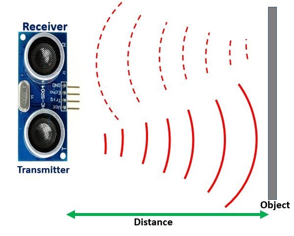
In this section, we will see how HC-SR04 ultrasonic sensor work. As you mentioned earlier, it consists of one ultrasonic transmitter circuit and one ultrasonic receiver circuit. The ultrasonic transmitter circuit converts the electrical signals into 40kHz ultrasonic sound waves. On the other hand, an ultrasonic receiver listens to these ultrasonic sound waves and if the receiver circuit receives these ultrasonic sound waves, it produces a pulse on the output pin. The width of this pulse or pulse duration can be used to measure the distance.
Distance Measurement Steps
Now let’s see the steps to initiate distance ranging or get echo pulse output:
- First of all, we apply 10 microseconds pulse to the Trigger pin of HC-SR04 sensor from general purpose input output pin of TM4C123 microcontroller.
- As a result, the transmitter circuit produces 8 pulses burst of ultrasound waves and each pulse has 40KHz frequency.
- As soon as all eight pulses are transmitted through the air, the echo pin goes high. In other words, the output echo pin makes transition from an active low to active high level.
- The echo pin remains active high until the ultrasonic sound wave does not reflect back to the receiver circuit after striking the object Under test.
- As soon as the ultrasonic signal received by the receiver circuit after striking with an object, the echo pin goes low.
- By measuring the width of the output pulse, we can measure the distance.
The pulse width can vary between 150 µS to 25 mS depending on the distance between the sensor and the obstacle. More the distance, the more time the sonar sound wave takes to receive after reflecting back.
Note: If there is no obstacle or out of the range of the maximum range of the sonar sensor ( 400cm), the transmitted signal will not reflect back. In this case, the echo output signal will go high for 38ms. Hence, if the width of the output pulse is 38ms, that means there is no object in the range of the obstacle sensor. Hence, the measured distance will be zero.
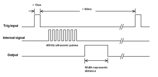
The figure below shows the timing diagram and it illustrates all the steps metioned above.
Measure HC-SR04 Output Pulse width using TM4C123
Now let’s see how to measure the output signal time or pulse duration of the HC-SR04 sensor. As you know that the time duration for which the output signal remains high depends on the distance between the ultrasonic sensor and the object under test. Greater the distance, the higher the time it will take by the Ultrasonic wave to reflect to the receiver circuit. Therefore, by measuring this time we can measure the distance between the sensor and the object.

In idle condition, when the sensor is not initiated by applying a trigger signal, the echo output signal remains active low. When we want to measure the distance, we apply a 10us pulse to the trigger input. In response, the HC-SR04 sensor produces a burst of 8 sonar wave pulses and raises its echo output pin active high. That means a rising edge occurs at the echo pin. After that as soon as the ultrasonic wave is detected by the receiver circuit, echo output goes low which means a falling edge occurs. Therefore, the time between two consecutive rising and falling edges gives us the pulse duration.
TM4C123 Timers and Pulse Duration
TM4C123 microcontroller timers can be in input edge timer capture mode. In this mode, timers can measure time between events such as rising or falling edges. For example, read the TM4C123 timer value when the rising edge is captured by the GPIO pin of TM4C123 microcontroller and also read the timer value when the falling edge is detected. After that takes the difference of two measured timer values, it will give you pulse duration.
In the previous tutorial, we have posted an in-depth guide to measure pulse duration using TM4C123 Timers. You must read this post:
In short, by measuring the time of this output pulse with TM4C123 timers, we can measure the distance.
Convert HC-SR04 Ouput Pulse Duration into Distance
Once we measured the output pulse duration, the distance can be calculated by using distance speed and time relationship that is:
S = v x t
In this equation, S, t, and v are distance, time, and speed respectively. Here time (t) is the pulse duration of the ultrasonic output signal. But how do we find the speed of ultrasonic waves? That’s pretty easy. If you studied physics in high school, you may remember that ultrasonic waves travel with the speed of sound. The speed of sound in air is 340 m/sec meters per second.
But as per the datasheet of the HC-SR04 ultrasonic sensor, the value of speed should be in units of a centimeter per second (cm/s). To convert speed into cm/sec, multiply 340 with 100. The result will be 34000cm/sec. Hence, the above formula to calculate distance from pulse duration becomes:
S = 34000cm/sec x t
But there is one more point to consider here that is the time taken by the ultrasonic wave to reach the obstacle and reflect back to the receiver indicates the distance for both forward and reverse path. Hence, we should also divide the above equation by 2 to get one way distance.
S = ( 34000cm/sec x t ) / 2
HC-SR04 Driver for TM4C123 MCU
Follow these steps to write API:
- First, make any TM4C123 microcontroller GPIO as a digital output pin to send the trigger signal to the ultrasonic sensor.
If you don’t know how to configure GPIO pins of TM4C123 microcontroller as digital output pins, read this guide:
How to use GPIO pins of TM4C123G Tiva launchPad
- Create a precise microseconds delay function using TM4C123 Timer
- Initialize another Timer module of TM4C123 microcontroller in input edge time mode and configure the respective GPIO capture pin of Timer as a digital input pin.
We have previously posted tutorials on TM4C123 microcontroller timers. If you want to explore further on how to create delay and configure timer in input-edge time mode, read these guides:
- 4. Now make the digital output pin active high followed by a 10 microseconds delay using the microseconds delay function
- After that, make the digital pin active low. Steps 2-4 will produce a 10us pulse. Connect this pulse signal with the trigger pin of the HC-SR04 range sensor.
- After that wait for the event to occur on the input edge capture pin. When the rising edge of the echo output signal occurs on the input edge capture pin of TM4C123, reads the content of the Timer register and saves its value in an integer variable.
- Again, wait for the falling edge of the echo output signal. When the input capture pin detects the falling edge, save the content of the timer register into another variable.
- Now take the difference of two measured time values, it will give us the pulse duration.
- In the end, convert the pulse duration into distance using the formula that we derived in the last section.
Distance Measurement Code TM4C123
This example code measures the distance using the HC-SR04 Ultrasonic range sensor. It displays the measured distance value on the computer using the UART communication module of TM4C123. Timer0A is used to measure distance by measuring the pulse duration of the Echo output signal. Timer1A is used to make a precise microsecond delay function.
/* This example code Measures the distance using HC-SR04 Ultrasonic range sensor*/
/* It displays the measured distance value on computer using UART communication moduel of TM4C123 */
/* Timer0A is used to measure distance by measuring pulse duration of Echo output signal */
/* Timer1A is used to make percise microsecond delay function */

/*header files for TM4C123 device and sprintf library */
#include "TM4C123GH6PM.h"
#include <stdio.h>

/*Function prototype for Timer0A and UART module initialization */

uint32_t Measure_distance(void);
void Timer0ACapture_init(void);
void Delay_MicroSecond(int time);
void UART5_init(void);
void UART5_Transmitter(unsigned char data);
void printstring(char *str);
void Delay(unsigned long counter);

/* global variables to store and display distance in cm */
uint32_t time; /*stores pulse on time */
uint32_t distance; /* stores measured distance value */
char mesg[20];  /* string format of distance value */

/* main code to take distance measurement and send data to UART terminal */
int main(void)
{
Timer0ACapture_init();  /*initialize Timer0A in edge edge time */
UART5_init(); /* initialize UART5 module to transmit data to computer */
	while(1)
	{
time = Measure_distance(); /* take pulse duration measurement */
distance = (time * 10625)/10000000; /* convert pulse duration into distance */
sprintf(mesg, "\r\nDistance = %d cm", distance); /*convert float type distance data into string */
printstring(mesg); /*transmit data to computer */
Delay(2000);

	}

}


/* This function captures consecutive rising and falling edges of a periodic signal */
/* from Timer Block 0 Timer A and returns the time difference (the period of the signal). */
uint32_t Measure_distance(void)
{
    int lastEdge, thisEdge;

	  /* Given 10us trigger pulse */
	  GPIOA->DATA &= ~(1<<4); /* make trigger  pin high */
	  Delay_MicroSecond(10); /*10 seconds delay */
	  GPIOA->DATA |= (1<<4); /* make trigger  pin high */
	  Delay_MicroSecond(10); /*10 seconds delay */
	  GPIOA->DATA &= ~(1<<4); /* make trigger  pin low */

 	while(1)
	{
    TIMER0->ICR = 4;            /* clear timer0A capture flag */
    while((TIMER0->RIS & 4) == 0) ;    /* wait till captured */
	  if(GPIOB->DATA & (1<<6)) /*check if rising edge occurs */
		{
    lastEdge = TIMER0->TAR;     /* save the timestamp */
		/* detect falling edge */
    TIMER0->ICR = 4;            /* clear timer0A capture flag */
    while((TIMER0->RIS & 4) == 0) ;    /* wait till captured */
    thisEdge = TIMER0->TAR;     /* save the timestamp */
		return (thisEdge - lastEdge); /* return the time difference */
		}
	}
}

/* Timer0A initialization function */
/* Initialize Timer0A in input-edge time mode with up-count mode */
void Timer0ACapture_init(void)
{
    SYSCTL->RCGCTIMER |= 1;     /* enable clock to Timer Block 0 */
    SYSCTL->RCGCGPIO |= 2;      /* enable clock to PORTB */

    GPIOB->DIR &= ~0x40;        /* make PB6 an input pin */
    GPIOB->DEN |= 0x40;         /* make PB6 as digital pin */
    GPIOB->AFSEL |= 0x40;       /* use PB6 alternate function */
    GPIOB->PCTL &= ~0x0F000000;  /* configure PB6 for T0CCP0 */
    GPIOB->PCTL |= 0x07000000;

	  /* PB2 as a digital output signal to provide trigger signal */
	  SYSCTL->RCGCGPIO |= 1;      /* enable clock to PORTA */
	  GPIOA->DIR |=(1<<4);         /* set PB2 as a digial output pin */
	  GPIOA->DEN |=(1<<4);         /* make PB2 as digital pin */

    TIMER0->CTL &= ~1;          /* disable timer0A during setup */
    TIMER0->CFG = 4;            /* 16-bit timer mode */
    TIMER0->TAMR = 0x17;        /* up-count, edge-time, capture mode */
    TIMER0->CTL |=0x0C;        /* capture the rising edge */
    TIMER0->CTL |= (1<<0);           /* enable timer0A */
}


/* Create one microsecond second delay using Timer block 1 and sub timer A */

void Delay_MicroSecond(int time)
{
    int i;
    SYSCTL->RCGCTIMER |= 2;     /* enable clock to Timer Block 1 */
    TIMER1->CTL = 0;            /* disable Timer before initialization */
    TIMER1->CFG = 0x04;         /* 16-bit option */
    TIMER1->TAMR = 0x02;        /* periodic mode and down-counter */
    TIMER1->TAILR = 16 - 1;  /* TimerA interval load value reg */
    TIMER1->ICR = 0x1;          /* clear the TimerA timeout flag */
    TIMER1->CTL |= 0x01;        /* enable Timer A after initialization */

    for(i = 0; i < time; i++)
    {
        while ((TIMER1->RIS & 0x1) == 0) ;      /* wait for TimerA timeout flag */
        TIMER1->ICR = 0x1;      /* clear the TimerA timeout flag */
    }
}
void UART5_init(void)
{
	  SYSCTL->RCGCUART |= 0x20;  /* enable clock to UART5 */
    SYSCTL->RCGCGPIO |= 0x10;  /* enable clock to PORTE for PE4/Rx and RE5/Tx */
    /* UART0 initialization */
    UART5->CTL = 0;         /* UART5 module disbable */
    UART5->IBRD = 104;      /* for 9600 baud rate, integer = 104 */
    UART5->FBRD = 11;       /* for 9600 baud rate, fractional = 11*/
    UART5->CC = 0;          /*select system clock*/
    UART5->LCRH = 0x60;     /* data lenght 8-bit, not parity bit, no FIFO */
    UART5->CTL = 0x301;     /* Enable UART5 module, Rx and Tx */

    /* UART5 TX5 and RX5 use PE4 and PE5. Configure them digital and enable alternate function */
    GPIOE->DEN = 0x30;      /* set PE4 and PE5 as digital */
    GPIOE->AFSEL = 0x30;    /* Use PE4,PE5 alternate function */
    GPIOE->AMSEL = 0;    /* Turn off analg function*/
    GPIOE->PCTL = 0x00110000;     /* configure PE4 and PE5 for UART */
}
void UART5_Transmitter(unsigned char data)
{
    while((UART5->FR & (1<<5)) != 0); /* wait until Tx buffer not full */
    UART5->DR = data;                  /* before giving it another byte */
}

void printstring(char *str)
{
  while(*str)
	{
		UART5_Transmitter(*(str++));
	}
}
void Delay(unsigned long counter)
{
	unsigned long i = 0;

	for(i=0; i< counter*1000; i++);
}
/* This function is called by the startup assembly code to perform system specific initialization tasks. */
void SystemInit(void)
{
    __disable_irq();    /* disable all IRQs */

    /* Grant coprocessor access */
    /* This is required since TM4C123G has a floating point coprocessor */
    SCB->CPACR |= 0x00F00000;
}
How does code Work?
This code uses the TM4C123 microcontroller to measure distance with the HC-SR04 ultrasonic sensor and transmit the result via UART. Here’s how the code works, broken down into blocks:
Global Variables and Function Prototypes
- Global variables: Variables like
time,distance, andmesgstore the pulse duration, calculated distance, and formatted distance string respectively. - Function prototypes: Key functions like
Measure_distance(),Timer0ACapture_init(),Delay_MicroSecond(), andUART5_Transmitter()are declared to handle distance measurement, timer initialization, delays, and UART transmission.
Main Code
- Timer and UART Initialization: In the
mainfunction,Timer0ACapture_init()initializes Timer0A to capture pulse durations, andUART5_init()initializes UART5 for data transmission. - Distance Measurement Loop: The
Measure_distance()function is called to capture the pulse duration from the HC-SR04 sensor. This duration is then converted to a distance value using the formuladistance = (time * 10625)/10000000. - UART Transmission: The distance is formatted into a string using
sprintf(), then sent via UART using theprintstring()function. A delay is applied between each measurement.
Distance Measurement
- Trigger Signal: In
Measure_distance(), a 10-microsecond pulse is sent to the sensor trigger pin (PA4) to initiate distance measurement. - Edge Detection: The code detects a rising edge on PB6 (connected to the Echo pin) using Timer0A. It then captures the time for the rising edge (
lastEdge) and the falling edge (thisEdge). The difference between these timestamps gives the pulse duration.
Timer0A Initialization (Edge Time Mode)
- Configuring Timer0A: In
Timer0ACapture_init(), Timer0A is set in edge-time capture mode to capture the rising and falling edges of the pulse. Pin PB6 is used as an input to receive the Echo signal, while PA4 is used as the output to trigger the sensor.
Microsecond Delay Using Timer1A
- Precise Delay: The
Delay_MicroSecond()function uses Timer1A to generate precise microsecond delays. The timer is configured in periodic mode, and for each microsecond delay, the timer waits for a timeout flag before proceeding.
UART Initialization and Transmission
- UART5 Setup: The
UART5_init()function configures UART5 for communication with a baud rate of 9600. It configures PE4 and PE5 pins for UART transmission and reception. - Data Transmission: The
UART5_Transmitter()function sends individual bytes of data over UART, whileprintstring()sends a complete string.
This code combines timers, UART communication, and sensor interfacing to measure distance and transmit the result to a computer.
Keil uvision v5 Instructions
Note: If you are using Keil uvision v5, you should remove the void SystemInit(void) function from the above code. Because the startup file in Keil v5 already contains the function SystemInit().
After that follow these steps to build above code with Keil uvision 5:
The other issue with the SystemInit() function in the new system_TM4C123.c is that it configures the clock generation which results in a different system clock rate than the default 16 MHz frequency. But the above sample code works on the default 16 MHz system clock. Therefore, the above program creates timing issues with Keil v5. You may retain the default system clock rate in Keil v5, by the following steps:
- Expand the Project->Device to show system_TM4C123.c (startup)
- Double click to open the file in the editor window
- Find the line “#define CLOCK_SETUP 1” as the figure below
- Comment out the line
- Rebuild the project

The UART functions used in the code are developed in the previous tutorial available here:
This example code is written using Keil uvision. Now upload this code to TM4C123 Tiva C Launchpad.
Hardware Demo
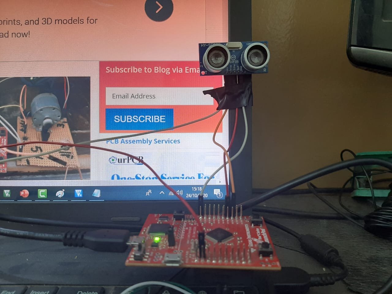
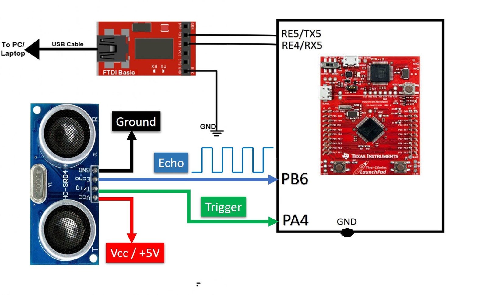
To see the hardware demo, make connections of HC-SR04 ultrasonic sensor with TM4C123 Tiva Launchpad according to this schematic diagram. Also, connect Tiva Launchpad with computer through USB to serial converter.
After that open the serial monitor by selecting the COM pin to which USB to Serial converter is connected through the UART5 module of TM4C123 MCU. You will get the distance measurements on the serial monitor.

Video Demo
Conclusion
In conclusion, this tutorial demonstrated how to interface the HC-SR04 ultrasonic sensor with the TM4C123 Tiva C Launchpad for distance measurement. By using the microcontroller’s timer in input-edge time mode, we can measure the duration of the active high output signal from the sensor, which corresponds to the distance between the sensor and the object. This setup provides a simple and efficient way to implement contactless distance measurement, showcasing the flexibility and functionality of both the HC-SR04 sensor and the TM4C123 microcontroller’s timer modules.
Other TM4C123 Tutorials:
- RPM Measurement using TM4C123 Tiva Launchpad
- Frequency Measurement using TM4C123 Timers
- Interrupt Processing ARM Cortex-M Microcontrollers
- GPIO Interrupts TM4C123 Tiva Launchpad
- MPU6050 interfacing with TM4C123G Tiva C Launchpad
- I2C Communication TM4C123G Tiva C Launchpad
Other Ultrasonic Sensor Related Tutorials:
- IoT based Contactless Water level Monitoring with ESP32 and HC-SR04
- Ultrasonic sensor interfacing with pic microcontroller
- Distance measurement using Ultrasonic sensor and Arduino
- Pic Based Ultrasonic Radar System for distance measurement
- VL53L0X LIDAR Distance Sensor Interfacing with Arduino
- Advanced Informative Blind Stick Using GPS and GSM Module
- IoT based Liquid Level Monitoring System
- Contactless Liquid Level Controller System using pic microcontroller
will u please elaborate the distance formula in the code ?
Hi,
you can look into this section:
http://microcontrollerslab.com/hc-sr04-ultrasonic-sensor-interfacing-with-tm4c123-tiva-c-launchpad/#Convert_HC-SR04_Ouput_Pulse_Duration_into_Distance
I am not sure this code working correctly, since I tried this code with Keil vision-4 and also updated UART5->IBRD = 208 and UART5->FBRD = 35 for Xtal = 80 MHz. I couldn’t anything in serial monitor output of RealTerm.
Hi Micheal,
It works perfectly fine for us as you can see from the outputs shown in the article. Can you tell me which version of Keil vision you are using?
You can try with Keil vision 4. Because in different versions of Keil vision 5, SystemInit() is defined in different ways. But it works fine for all Keil vision 4 versions. You can try with Keil vision 4 and let me know. I hope it will help. Thanks
I’m working on Keil vision 4 and taking 5V Vcc signal from other card(Arduino Uno), then make common ground for both Tiva and Arduino. But, I still see nothing in RealTerm Screen about measurement as you observed in the about.
Thanks
Make sure you are using FTDI USB to TTL converter correctly. Follow thess points:
1. Check USB to TTL converter connection with Tiva Launchpad. The GND terminal should be common for Tiva, FTDI cable and Arduino.
2. Also, see if you have installed drivers correctly.
3. Select correct COM port by checking it from device manager
4. Select the right baud rate 9600 in your serial terminal
I hope it will help. Let me know if it works.
It has worked, thank you.
I am glad. It helped.
Hi, when I try to run this code, ı get error and it does not work I checked it error in the last function system init, could you help me
Which version of Keil uvision you are using? If you are using Keil vision 5, remove the system init function and if you are using Keil vision 4 then you need the system init function.
Hi! I removed the system init func. Now there is no error but Code does not work properly. When I run putty it does not show the any information on black screen. Baud rate 9600, flowcontrol = no , and USB PLL on COM6
If you are using Keil uvision 5, disable the floating-point unit from the project setting page and then run the code.
Hi.İ got same problem (black screen there si no information on putty).When i disable the fpu from the project.i got an error how can i solve this problem.
Hi,
which version of Kiel uvision you are using? If you are using Keil uvision v5, remove the void SystemInit(void) function from the above code.
Make sure you are using FTDI USB to TTL converter correctly. Follow these points:
1. Check USB to TTL converter connection with Tiva Launchpad. The GND terminal should be common for Tiva, FTDI cable and Arduino.
2. Also, see if you have installed drivers correctly.
3. Select the correct COM port by checking it from the device manager
4. Select the right baud rate 9600 in your serial terminal
I hope it will help. Let me know if it works.
Make sure you are using FTDI USB to TTL converter correctly. Follow thess points:
1. Check USB to TTL converter connection with Tiva Launchpad. The GND terminal should be common for Tiva, FTDI cable and Arduino.
2. Also, see if you have installed drivers correctly.
3. Select correct COM port by checking it from device manager
4. Select the right baud rate 9600 in your serial terminal
I hope it will help. Let me know if it works.
In this tutorial, you have done polling to see for the rising and the falling edge. i want to do that using interrupts. Pls help on which on bits I should focus. Thanku
Hi,
You can check this Timer interrupt tutorial where I have used a timer interrupt to generate a delay. But you can start and stop the time based on rising and falling edge and you can modify the code accordingly:
Timer Interrupt TM4C123
Hi, even though I disabled fpu , remove the systeminit function and changed the startup content, the putty has a black screen, how do I fix it? I use keil 5.
Hi,
Please try this UART TM4C123 first and see if it works for you. Let me know if you are able to perform communication with PC.
Hello,
I reviewed your project ”HC-SR04 Ultrasonic Sensor Interfacing with TM4C123 – Distance Measurement Example”. We were asked to do such a project in our school. I would be very happy if you could help us with this. The HC-SR04 ultrasonic sensor also wants us to connect it to our connections edge=PA4, Trig=PB6. In your project, the opposite is the case. Can you help me how can I do this?
For this, you need to change the PB6 pin as a digital output pin and apply trigger signal by PB6 by modifying these lines in the code:
 GPIOA->DATA &= ~(1<<4); /* make trigger  pin high */
Delay_MicroSecond(10); /*10 seconds delay */
GPIOA->DATA |= (1<<4); /* make trigger  pin high */
Delay_MicroSecond(10); /*10 seconds delay */
GPIOA->DATA &= ~(1<<4); /* make trigger  pin low */
For edge detection, you need to check from the datasheet which timer is used to detect edge with PA4 pin.
But in Thé PA port there is no T0CCP0 module. İn your code you used this module for the ultrasonic distance sensor’s echo pin. But i want to connect PA4 and ultrasonic distance sensor’s echo pin. So i have this problem. How can i solve it ?
Well, it would be unfair if I would share the solution for your class assignment. You need to figure it out to polish your problem solving skills.
You are absolutely right sir, but we have been trying for days and we dont solve this problem. Unfortunately we have to deliver it tomorrow. Please help us.
If running this on Keil, and plugging in the TIVA in through the micro-USB can I just use the UARTprintf() function instead of having to use a USB to the serial converter? Or is it necessary to use the serial converter?
I tried with that but it was creating issue. That’s why I used another UART channel.
I am using termite as the output by the way, using a 11500 baud rate.
Does anyone know how to interface the fingerprint sensor and the TM4C123 Tiva series launchpad. ! If there’s any project or tutorial please share the link.
Hi there, I am still working on this project and in the TIMER0ACapture_init function it doesn’t seem to be going through the “while((TIMER0->RIS & 4) == 0) ; ” loop. do you know a fix to this? Or could we discuss how to fix this issue through email I would love to learn from someone more experienced than myself. Kind of lost on what to do to debug this at the moment.
Hi, Im wondering on how to get the measure_distance section of the code.
im confused on how you made the while loops and if statements, to me it looks like you embedded the while loop with the if statement together.
what I mean is
while( … … …..)
if( …. …. …. )
{
}
this is what the code looks like to me, shouldnt it be
while( .. … )
{
}
if(… …. ..)
{
}
?
I cant get the code to run on my computer.
hey! Instead of GPIOB->DIR &= ~0x40; can I write GPIO_PORTB_DIR_R &=~0x40; ? and the rest of the steps also in the same format?
No, unless you define your own register definition file.
Thanks for your reply.
I am actually not that much aware of UART module..But I shall soon learn that..I want know if this is the way we code for UART module?
What I mean is..Is it syntactically the same way we code a pin as GPIO pin and UART pin?
could you please explain the magic number used in the distance formula
specifically how you derived [ distance = (time * 10625) / 10000000 ] from [ S = ( 34000cm/sec x t ) / 2 ]
Please check explanation part.
Could you please explain the reason behind commenting the clock setup and not using the floating point in code?
hey!!
can you tell me if I want to make the project using multiple sonic sensor how can I do that?
really nice work especially for a bigginner like me .would you mind providing the steps and code for HC-SR501PIR motion sensor.i will really appreciate