In this tutorial, we learn about the SSD1306 0.96-inch I2C OLED display and how to interface it with Raspberry Pi Pico using MicroPython. An OLED (Organic Light-Emitting Diode) display is a popular choice in embedded projects because each pixel generates its own light, eliminating the need for a backlight. This results in excellent contrast, wide viewing angles, and deep blacks. OLED displays are commonly used for displaying text, bitmap images, geometric shapes, and even real-time clock readings. They are compact, energy-efficient, and cost-effective, making them ideal for battery-powered and portable embedded systems.
In this guide, we will first explore the SSD1306 OLED display module and its pinout. Then we will connect it to the Raspberry Pi Pico using the I2C protocol, install the necessary MicroPython library, and write scripts to display text messages, draw pixels, lines, and shapes on the screen.
Recommended Components
The following components are used in this project or are helpful for getting started with Raspberry Pi Pico development.
| Component | How it’s used in this project | Buy on Amazon |
|---|---|---|
| Raspberry Pi Pico | The RP2040 microcontroller board used in this tutorial. | Check Price |
| SSD1306 OLED Display | 0.96-inch 128×64 I2C OLED display used to show text and graphics. | Check Price |
| Breadboard | Solderless breadboard for building the circuit. | Check Price |
| Jumper Wires | Male-to-male / male-to-female wires for the connections. | Check Price |
As an Amazon Associate we earn from qualifying purchases. Prices and availability are accurate as of the date/time indicated and are subject to change.
Prerequisites
Before starting this tutorial, make sure you have the following set up on your system:
- Python 3 installed on your computer
- MicroPython firmware flashed on your Raspberry Pi Pico
- Thonny IDE or uPyCraft IDE installed and configured
If you have not set up MicroPython on your Raspberry Pi Pico yet, follow one of the guides below:
- Getting Started with Raspberry Pi Pico using Thonny IDE
- Getting Started with Raspberry Pi Pico using uPyCraft IDE
SSD1306 0.96-inch OLED Display
Although several types of OLED displays are available in the market, we will be using the SSD1306 0.96-inch OLED display module. The core component driving all these displays is the SSD1306 controller IC, which communicates with microcontrollers over the I2C or SPI protocol. OLED displays vary in size, color (monochrome, blue, yellow, or dual-color), and shape, but they are programmed in a similar way.
The SSD1306 0.96-inch OLED we are using has a resolution of 128×64 pixels and communicates over the I2C protocol with the Raspberry Pi Pico. It is inexpensive and widely available from electronics suppliers. The display does not require an external backlight, which means it consumes significantly less power compared to LCD displays of the same size.
Below you can see the pinout of the OLED display.
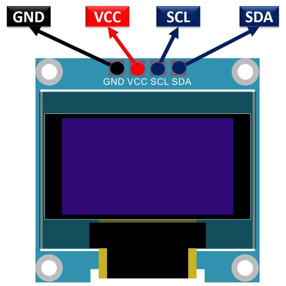
SSD1306 OLED Pinout
The SSD1306 OLED module has four pins labeled VCC, GND, SCL, and SDA:
- VCC: Power supply pin. Connect to 3.3V on the Raspberry Pi Pico. The display supports an operating voltage of 3.3V to 5V.
- GND: Ground pin. Connect to the common ground.
- SCL: Serial Clock Line. This pin carries the clock signal generated by the I2C master (the Raspberry Pi Pico).
- SDA: Serial Data Line. This pin is used for bidirectional data transmission between the display and the microcontroller.
Here is a summary of the SSD1306 OLED display specifications:
| Size | 0.96 inch |
| Terminals | 4 |
| Pixels | 128×64 |
| Communication Type | I2C (also available with SPI on some modules) |
| VCC | 3.3V – 5V |
| I2C Address | 0x3C (default) or 0x3D |
| Operating Temperature | -40°C to +80°C |
One important note: the default I2C address of the SSD1306 is 0x3C. Some modules allow you to change this to 0x3D by soldering a jumper pad on the back of the module. If you have two OLED displays on the same I2C bus, you can use different addresses for each one.
Interfacing SSD1306 OLED Display with Raspberry Pi Pico
The OLED display requires a voltage in the range of 3.3V to 5V. Since the Raspberry Pi Pico operates at 3.3V logic levels, we connect the VCC pin of the OLED to the 3.3V output of the Pico. The SCL and SDA lines are connected to the corresponding I2C pins on the Pico, and the ground pins of both devices are connected together.
Raspberry Pi Pico I2C Pins
The Raspberry Pi Pico has two hardware I2C controllers: I2C0 and I2C1. Each controller can be mapped to multiple GPIO pins, giving you flexibility in your wiring. The table below shows which GPIO pins are available for each I2C controller. You must configure the desired GPIO pins in your MicroPython code when initializing the I2C bus.
| I2C Controller | GPIO Pins |
| I2C0 – SDA | GP0/GP4/GP8/GP12/GP16/GP20 |
| I2C0 – SCL | GP1/GP5/GP9/GP13/GP17/GP21 |
| I2C1 – SDA | GP2/GP6/GP10/GP14/GP18/GP26 |
| I2C1 – SCL | GP3/GP7/GP11/GP15/GP19/GP27 |
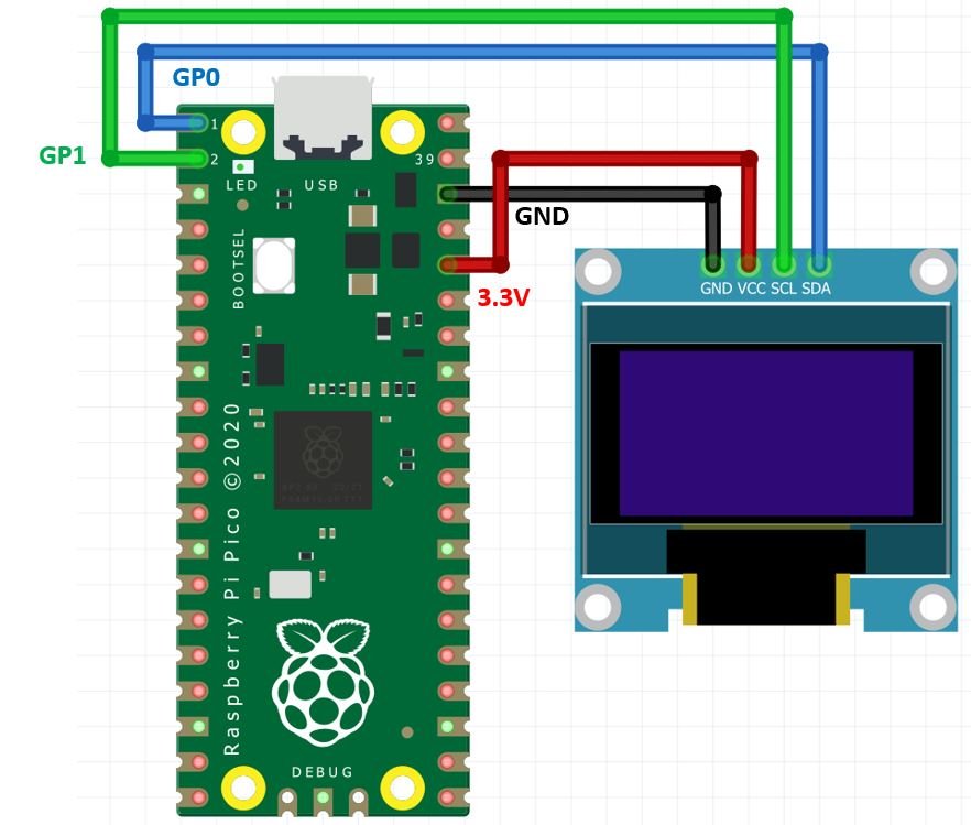
In this tutorial, we use GP0 for SDA and GP1 for SCL, which belong to the I2C0 controller.
| SSD1306 OLED Display | Raspberry Pi Pico |
| VCC | 3.3V |
| SDA | GP0 (I2C0 SDA) |
| SCL | GP1 (I2C0 SCL) |
| GND | GND |
Components Required
- Raspberry Pi Pico
- SSD1306 0.96-inch I2C OLED Display
- Jumper Wires
- Breadboard (optional but recommended)
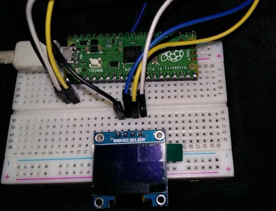
Schematic: Raspberry Pi Pico with OLED
Follow the schematic diagram below and connect the components accordingly. Make sure all connections are firm, especially the SDA and SCL lines, as loose connections can cause communication errors.
Installing the SSD1306 OLED MicroPython Library
To control the SSD1306 OLED display with MicroPython, we need to install the micropython-ssd1306 library. This library provides easy-to-use functions for drawing text, shapes, and images on the display. Follow the steps below to install it using Thonny IDE’s built-in package manager.
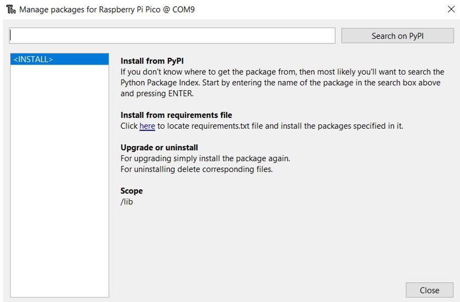
- Open Thonny IDE with your Raspberry Pi Pico plugged into your computer. Go to Tools > Manage Packages. This will open the Thonny Package Manager.
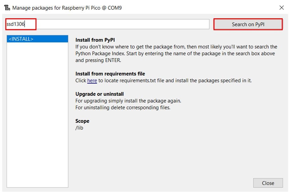
- In the search box, type ssd1306 and click the Search on PyPI button.
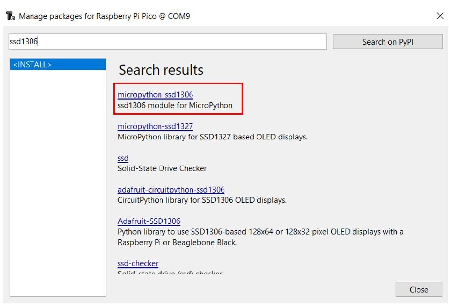
- From the search results, select micropython-ssd1306.
Click the Install button to install the library onto your Raspberry Pi Pico.
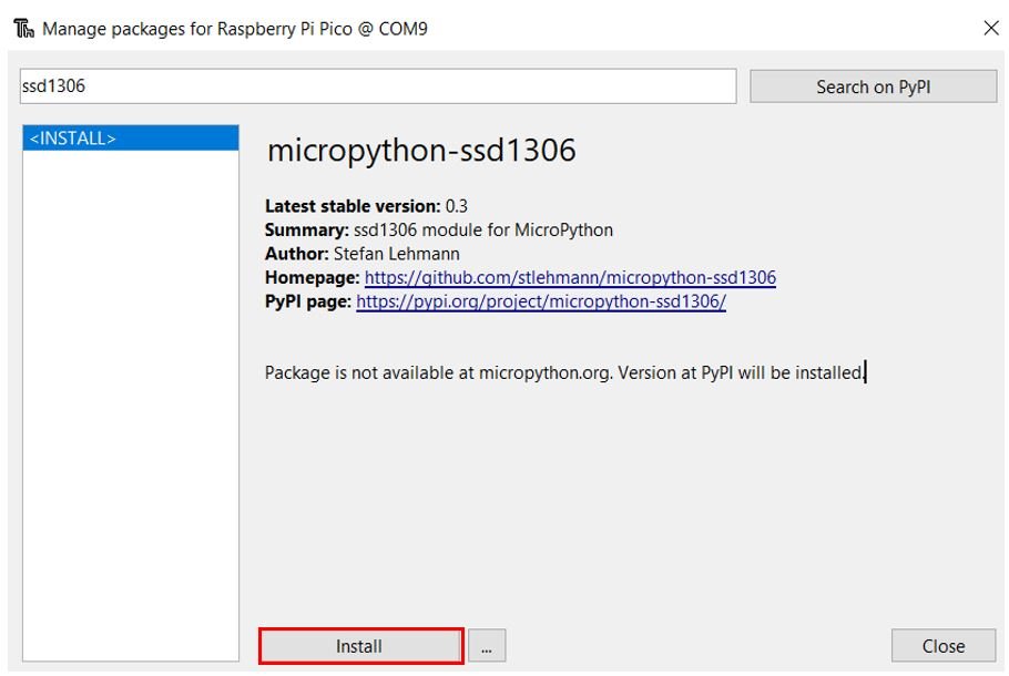
After a few moments, the library will be successfully installed. If you encounter a certificate error during the installation (as some users have reported), you can manually download the ssd1306.py file from the MicroPython GitHub repository and upload it directly to your Pico using Thonny’s file manager.
MicroPython Script: Displaying Text Messages on OLED Display
Now that the library is installed and the hardware is connected, let us write our first MicroPython script to display text on the OLED screen. This example will display three lines of text on the display.
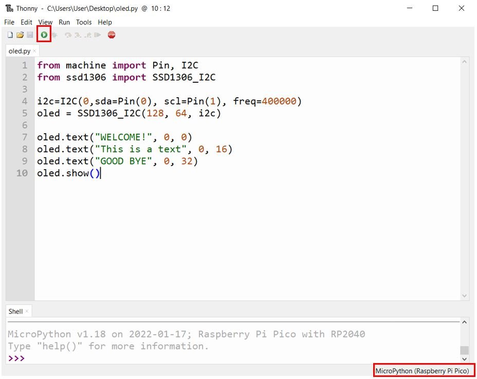
Open a new file in Thonny IDE, save it as oled.py, and copy the code below into the file.
from machine import Pin, I2C
from ssd1306 import SSD1306_I2C

i2c=I2C(0,sda=Pin(0), scl=Pin(1), freq=400000)
oled = SSD1306_I2C(128, 64, i2c)

oled.fill(0)             # Clear the display
oled.text("WELCOME!", 0, 0)
oled.text("This is a text", 0, 16)
oled.text("GOOD BYE", 0, 32)
oled.show()
How the Code Works
Importing Libraries
We begin by importing the Pin and I2C classes from the machine module. The Pin class allows us to configure specific GPIO pins, and the I2C class handles the I2C communication protocol. We also import the SSD1306_I2C class from the ssd1306 library, which provides high-level methods for controlling the OLED display.
from machine import Pin, I2C
from ssd1306 import SSD1306_I2C
Initializing the I2C Bus
Next, we initialize the I2C bus using the I2C() constructor. This function accepts four arguments:
- Channel: The I2C controller number (0 for I2C0, 1 for I2C1)
- sda: The GPIO pin used for the SDA (data) line
- scl: The GPIO pin used for the SCL (clock) line
- freq: The communication frequency in Hz. We set this to 400000 (400 kHz, the fast-mode I2C speed)
i2c=I2C(0,sda=Pin(0), scl=Pin(1), freq=400000)Creating the OLED Object
We create an instance of the SSD1306_I2C class, passing three parameters: the display width in pixels (128), the display height in pixels (64), and the I2C bus object. This object represents the OLED display and provides all the drawing methods we will use.
oled = SSD1306_I2C(128, 64, i2c)Displaying Text on the OLED
The text() function is used to render a string on the display buffer. It accepts up to four arguments:
- String: The text to display (must be a string)
- X position: The horizontal pixel position where the text begins (0 is the leftmost column)
- Y position: The vertical pixel position where the text begins (0 is the top row)
- Color: Optional. Use
1for white (default) or0for black (to write black text on a white background)
The built-in font used by the SSD1306 library is 8 pixels tall. To avoid text overlap, we space each line 16 pixels apart (Y positions of 0, 16, and 32). We also call oled.fill(0) before writing text to clear any previous content from the display buffer.
oled.fill(0)            # Clear the display buffer
oled.text("WELCOME!", 0, 0)
oled.text("This is a text", 0, 16)
oled.text("GOOD BYE", 0, 32)
Finally, the show() method sends the contents of the display buffer to the OLED controller, which updates the physical screen. Without calling show(), nothing will appear on the display.
oled.show()Demonstration
Save the file in Thonny IDE by clicking the Save button. Make sure the correct board (Raspberry Pi Pico) is selected in the interpreter settings. Then click the Run button to upload and execute the script.
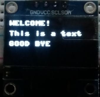
The OLED display will show the three messages as illustrated below:
Draw Pixels, Lines, and Shapes on OLED with Raspberry Pi Pico
Beyond displaying text, the SSD1306 library includes built-in methods to draw graphical primitives such as individual pixels, horizontal and vertical lines, diagonal lines, and both filled and unfilled rectangles. This makes it straightforward to build simple user interfaces or data visualizations on a small screen. By the end of this section, you will be able to display the following:
- A single pixel at any position
- Horizontal, vertical, and diagonal lines
- Unfilled and filled rectangles
MicroPython Script
The following script runs in an infinite loop, displaying each graphical element for 2 seconds before clearing the screen and moving to the next one. It imports the sleep function from the time module to add the delay.
from machine import Pin, I2C
from ssd1306 import SSD1306_I2C
from time import sleep

i2c=I2C(0,sda=Pin(0), scl=Pin(1), freq=400000)
oled = SSD1306_I2C(128, 64, i2c)

while True:
      # Draw a single pixel at the center of the screen
      oled.pixel(64,32,1)
      oled.show()
      sleep(2)
      oled.fill(0)

      # Draw a horizontal line across the middle
      oled.hline(0,32,128,1)
      oled.show()
      sleep(2)
      oled.fill(0)

      # Draw a vertical line along the left edge
      oled.vline(0, 0, 64, 1)
      oled.show()
      sleep(2)
      oled.fill(0)

      # Draw a diagonal line from top-left to bottom-right
      oled.line(0, 0, 128, 64, 1)
      oled.show()
      sleep(2)
      oled.fill(0)

      # Draw an unfilled rectangle
      oled.rect(20, 20, 64, 32, 1)
      oled.show()
      sleep(2)
      oled.fill(0)

      # Draw a filled rectangle
      oled.fill_rect(20, 20, 64, 32, 1)
      oled.show()
      sleep(2)
      oled.fill(0)
Before drawing each new shape, we call oled.fill(0) to clear the display buffer. This ensures that previously drawn content does not interfere with the next shape. After drawing each shape, we call oled.show() to push the buffer contents to the screen.
Drawing a Single Pixel
The pixel(x, y, color) function places a single pixel at the coordinates (x, y). The x-axis runs from 0 (left edge) to 127 (right edge), and the y-axis runs from 0 (top edge) to 63 (bottom edge). Setting the color to 1 draws a white pixel, while 0 draws a black pixel (effectively erasing it). In our example, we draw a pixel at (64, 32), which is the center of the 128×64 display.
oled.pixel(64,32,1)Drawing Lines
The SSD1306 library provides three dedicated line-drawing functions:
Horizontal Line — hline(x, y, width, color): Draws a horizontal line starting at position (x, y) and extending for the specified number of pixels to the right. In our example, hline(0, 32, 128, 1) draws a horizontal line across the full width of the display at the vertical midpoint.
oled.hline(0,32,128,1)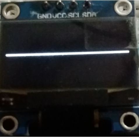
Vertical Line — vline(x, y, height, color): Draws a vertical line starting at position (x, y) and extending downward for the specified number of pixels. In our example, vline(0, 0, 64, 1) draws a vertical line along the entire left edge of the display.
oled.vline(0, 0, 64, 1)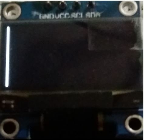
Diagonal Line — line(x1, y1, x2, y2, color): Draws a straight line between two points specified by their (x1, y1) and (x2, y2) coordinates. This function uses the Bresenham line algorithm internally. In our example, line(0, 0, 128, 64, 1) draws a diagonal from the top-left corner to the bottom-right corner of the screen.
oled.line(0, 0, 128, 64, 1)
Drawing Rectangles (Unfilled and Filled)
The library provides two rectangle-drawing functions:
Unfilled Rectangle — rect(x, y, width, height, color): Draws only the outline of a rectangle. The parameters (x, y) define the top-left corner of the rectangle, and width and height define its dimensions in pixels. In our example, rect(20, 20, 64, 32, 1) draws a white-outlined rectangle starting at (20, 20) with a width of 64 pixels and a height of 32 pixels.
oled.rect(20, 20, 64, 32, 1)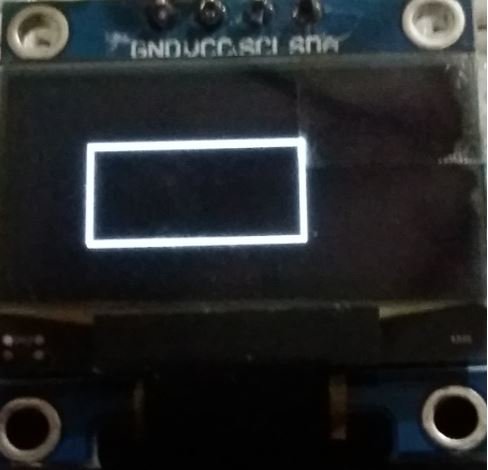
Filled Rectangle — fill_rect(x, y, width, height, color): Draws a solid rectangle filled with the specified color. It uses the same parameters as rect(). In our example, fill_rect(20, 20, 64, 32, 1) draws a solid white rectangle at the same position and dimensions as the outline rectangle above.
oled.fill_rect(20, 20, 64, 32, 1)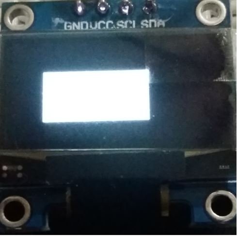
Demonstration
Save the script in Thonny IDE and click the Run button. Each shape will be displayed on the OLED screen for 2 seconds before the display is cleared and the next shape appears. Watch the video below to see this in action.
Troubleshooting Tips
If your OLED display is not working as expected, here are some common issues and solutions to try:
- Nothing shows on the display: Double-check your wiring. Make sure VCC is connected to 3.3V, GND to ground, and that the SDA and SCL lines are connected to the correct GPIO pins as defined in your code.
- OSError or I2C error: This usually means the Pico cannot detect the OLED on the I2C bus. Verify your wiring, and use an I2C scanner script to confirm the device address. You can scan for devices with:
i2c.scan()which returns a list of detected I2C addresses. - Wrong I2C address: The default address for SSD1306 is 0x3C (decimal 60). If
i2c.scan()returns 0x3D (decimal 61), you need to specify the address manually:oled = SSD1306_I2C(128, 64, i2c, addr=0x3D) - Library installation error: If the PyPI installation fails due to a certificate error, manually download the ssd1306.py file from the MicroPython GitHub repository and copy it to your Pico using Thonny’s file manager.
- Display is upside down: Some OLED modules from different manufacturers have flipped orientations. The SSD1306 library does not natively support display rotation, but you can achieve this by modifying the driver file or using a different library that supports rotation.
You may like to read:
- Raspberry Pi Pico GPIO Programming with MicroPython – LED Blinking Examples
- Interface Push Button with Raspberry Pi Pico and Control LED
- Raspberry Pi Pico ADC with Voltage Measurement Examples
- PIR Motion Sensor with Raspberry Pi Pico using External Interrupts
- Raspberry Pi Pico PWM MicroPython LED Fading Examples
- Generate Delay with Raspberry Pi Pico Timers using MicroPython
If a person tries to download the ssd1306 from PyPi they will get an error and the error is invalid certificate. I had to go to github and create thessd1306 from the raw code and also the supporting files needed for ssd1306 to work.
I didn’t have any problems. The library installed fine. I am on latest Windows 10 with Thonny 4.0.1
How would one display on the OLED the time from a DS3231 real time clock ?
Thanks
Excellent, all worked first time. Very helpful, thank you.
OMG, so easy and simple;
Best Guide EVER!
Worked perfectly for me – a first!