If you are new to Raspberry Pi Pico and want to explore its GPIO capabilities using MicroPython, then you have come to the right place. In this tutorial, we will show you how to use the GPIO pins of Raspberry Pi Pico as digital outputs using MicroPython firmware. We will connect LEDs to the GPIO pins and control them programmatically. By the end of this guide, you will have completed hands-on examples including single LED blinking, an alternate LED on/off method, and a three-LED chaser effect using MicroPython and Thonny IDE.
Recommended Components
The following components are used in this project or are helpful for getting started with Raspberry Pi Pico development.
| Component | How it’s used in this project | Buy on Amazon |
|---|---|---|
| Raspberry Pi Pico | The RP2040 board whose GPIO pins drive the LEDs. | Check Price |
| 5mm LEDs | LEDs blinked and chased from the GPIO pins. | Check Price |
| 220 Ω Resistors | Current-limiting resistors in series with each LED. | Check Price |
| Breadboard | Solderless breadboard for assembling the LED circuits. | Check Price |
| Jumper Wires | Connecting wires between the Pico, resistors, and LEDs. | Check Price |
As an Amazon Associate we earn from qualifying purchases. Prices and availability are accurate as of the date/time indicated and are subject to change.
Prerequisites
Before starting this tutorial, make sure you have completed the following setup steps:
- Downloaded and installed the latest version of Python 3 on your PC.
- Downloaded and installed the latest version of Thonny IDE.
- Flashed the MicroPython firmware onto your Raspberry Pi Pico board.
If you have not performed these steps yet, follow our detailed step-by-step guide:
If you prefer using uPyCraft IDE instead of Thonny, you can check this alternative getting started guide:
After completing the initial setup, we will now learn how to blink a single LED with the Raspberry Pi Pico board using MicroPython and the Thonny IDE. But first, let us familiarize ourselves with the GPIO pins of the Raspberry Pi Pico.
What are GPIOs?
GPIO stands for General Purpose Input/Output. GPIO pins are digital signal pins found on microcontrollers and single-board computers like the Raspberry Pi Pico. These pins can be configured in either input or output mode and are used to communicate with external hardware devices and sensors.
In input mode, GPIO pins read the state of external devices such as buttons, switches, or sensors. They can detect whether a device is in an ON or OFF state, or detect changes in state over time. In output mode, GPIO pins produce electrical signals that can control other devices like LEDs, motors, relays, or buzzers. By changing the state of the pin between HIGH and LOW, you can turn devices on or off, or send specific signal patterns to achieve various functionalities.
GPIO pins offer great flexibility and allow users to interface with a wide range of hardware components, making them essential for embedded systems and electronics projects.
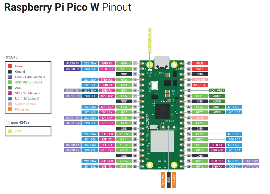
Raspberry Pi Pico GPIO Pins
The Raspberry Pi Pico exposes 26 multi-function GPIO pins from the total 36 GPIO pins available on the RP2040 microcontroller. Out of these 26 pins, 23 are digital-only pins and 3 pins (GP26, GP27, GP28) also support analog input via the built-in ADC (Analog-to-Digital Converter). The digital pins are labeled GP0, GP1, through GP22. Note that GP23, GP24, and GP25 are not exposed on the board’s pinout header and cannot be used for external connections (GP25 is internally connected to the onboard LED on the standard Pico). GP26, GP27, and GP28 complete the set of accessible GPIO pins. All 26 exposed GPIO pins can be configured as either digital input or digital output.
Each GPIO pin on the Raspberry Pi Pico can source or sink up to 12mA of current, and the total current across all GPIO pins should not exceed 50mA. The GPIO pins operate at 3.3V logic levels, so you should never connect 5V signals directly to the Pico’s GPIO pins as this could damage the board.

Recommended Reading: Raspberry Pi Pico – Getting Started Guide
MicroPython Digital Outputs
To configure Raspberry Pi Pico GPIO pins as digital outputs using MicroPython, follow these steps:
Step 1: Import the Pin module. The Pin class from the machine module is required to interact with the GPIO pins.
from machine import PinStep 2: Create a Pin object for the desired GPIO pin. Replace pin_number with the actual GPIO number you want to use. For example, to configure GPIO13 as a digital output:
led = Pin(13, Pin.OUT)Step 3: Set the pin value to control the output. Use the value() method to set the pin HIGH (3.3V) or LOW (0V):
led.value(1)  # Set the pin HIGH (LED turns on)
led.value(0)  # Set the pin LOW (LED turns off)
The Pin class constructor accepts the following parameters: Pin(pin_number, pin_mode, pull, value). The first argument is the GPIO pin number. The second argument defines the pin mode: Pin.OUT for digital output, Pin.IN for digital input, or Pin.OPEN_DRAIN for open-drain mode. The optional third argument enables internal pull-up (Pin.PULL_UP) or pull-down (Pin.PULL_DOWN) resistors, which are useful when using GPIO pins as digital inputs. The optional fourth argument sets the initial state of the pin as either HIGH (1) or LOW (0). By default, GPIO pins start in the LOW state after reset.
Blinking LED Example Raspberry Pi Pico
Now we will build our first project: blinking an external LED using Raspberry Pi Pico with MicroPython in Thonny IDE.

For this project, you will need the following components:
- Raspberry Pi Pico board
- One LED (any color)
- One 220 ohm resistor (current limiting)
- Breadboard
- Connecting wires (jumper wires)
LED Blinking Circuit Connection
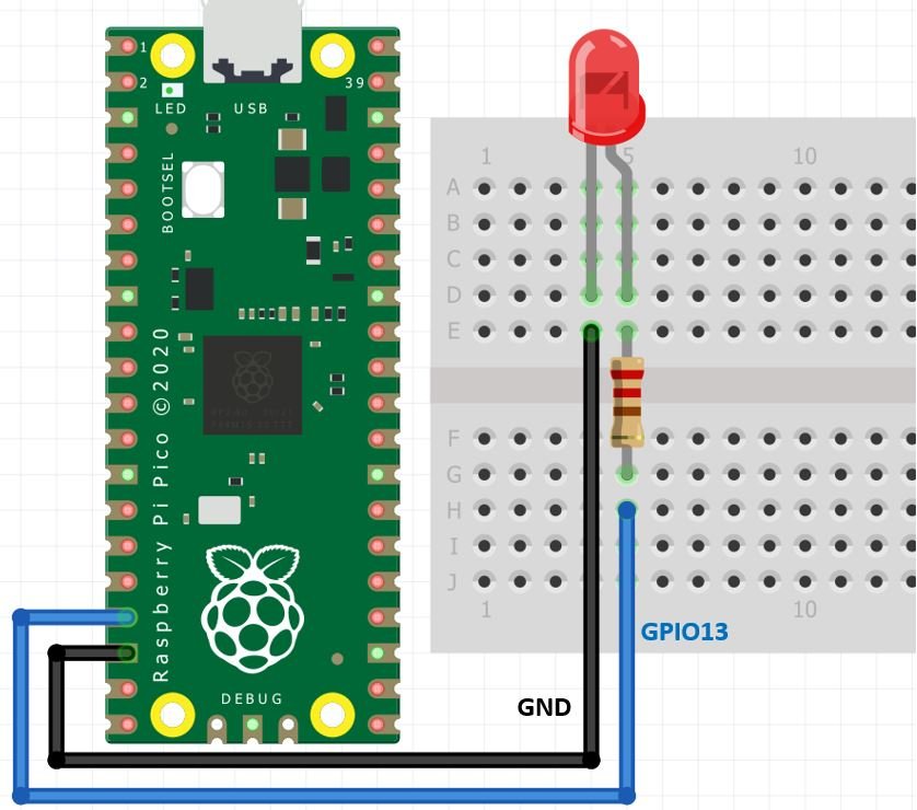
Connect the Raspberry Pi Pico to the LED as follows: connect GPIO13 of the Raspberry Pi Pico to the anode (longer leg) of the LED through a 220-ohm current limiting resistor. Connect the cathode (shorter leg) of the LED to any GND pin on the Pico board. The 220-ohm resistor is essential to limit the current flowing through the LED, preventing it from burning out. Without a current limiting resistor, the full 3.3V output from the GPIO pin could damage the LED.
Connect the components as shown in the schematic diagram below:
| LED | Raspberry Pi Pico |
|---|---|
| Anode (+) via 220Ω resistor | GPIO13 |
| Cathode (-) | GND |
LED Blinking MicroPython Script
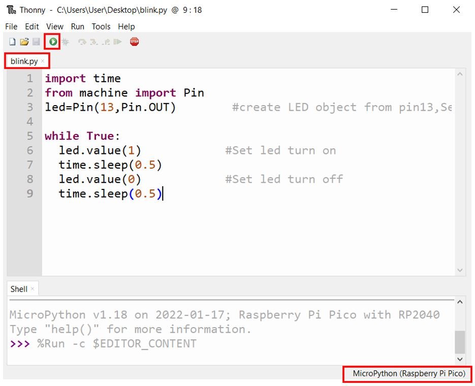
Now let us create the LED blinking script. Open Thonny IDE, create a new file by clicking File > New, and copy the following code into the editor:
import time
from machine import Pin
led = Pin(13, Pin.OUT)        # Create LED object on GPIO13, set as output

while True:
  led.value(1)            # Turn LED on
  time.sleep(0.5)         # Wait 0.5 seconds
  led.value(0)            # Turn LED off
  time.sleep(0.5)         # Wait 0.5 seconds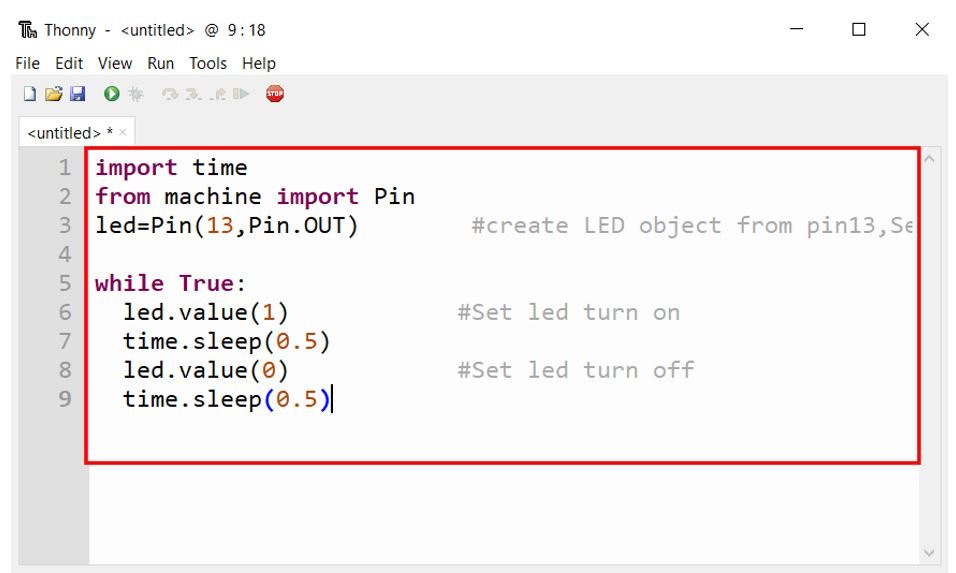
After entering the code, click the “Save” icon. A dialog box will appear giving you two options: save the file to your computer or directly to the Raspberry Pi Pico. For now, save it on your computer with the name blink.py (you can use any name, but make sure it ends with the .py extension).
Now click the “Run” button to execute the code on your Raspberry Pi Pico. Make sure the correct board (MicroPython Raspberry Pi Pico) is selected in the interpreter settings at the bottom right of Thonny.
How the Code Works
Let us break down each part of the code to understand how it works.
Importing the Required Libraries
In MicroPython, the machine module contains classes for different peripherals of the microcontroller such as GPIO, ADC, PWM, I2C, SPI, and more. Since we are working with GPIO pins in this tutorial, we import the Pin class from the machine module. We can create multiple instances of the Pin class to configure and control different GPIO pins independently.
from machine import PinThe time module provides functions for adding delays to our code. The sleep() function accepts a value in seconds (including decimal values for sub-second delays) and pauses the program execution for the specified duration.
import timeCreating the LED Pin Object
Next, we create an instance of the Pin class and assign it to a variable named led. You can use any descriptive variable name such as led_13, my_led, or output_pin. The first argument (13) specifies the GPIO pin number, and Pin.OUT configures it as a digital output.
led = Pin(13, Pin.OUT)The Infinite Loop and GPIO Control
The while True: statement creates an infinite loop that runs continuously. Inside the loop, we alternate between turning the LED on and off with a half-second delay between each state change, producing a blinking effect.
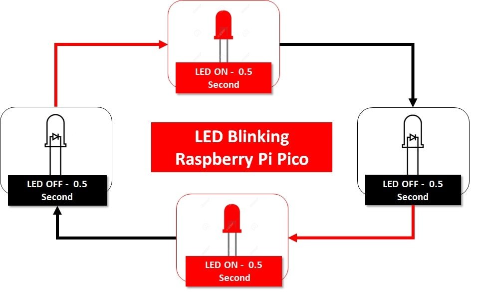
The led.value(1) call sets GPIO13 to a HIGH state (3.3V), which turns the LED on. After a 0.5-second delay using time.sleep(0.5), the led.value(0) call sets GPIO13 to a LOW state (0V), turning the LED off. Another 0.5-second delay follows before the loop repeats, creating a continuous blinking pattern at a rate of one blink per second.
Demonstration
After saving the code, press the Run button to upload and execute the file on your Raspberry Pi Pico. You will see the LED blinking at a rate of one second (0.5 seconds on, 0.5 seconds off) as shown in the video below:
Tip: You can change the blinking speed by modifying the time.sleep() values. For example, using time.sleep(0.1) will make the LED blink much faster, while time.sleep(2) will make it blink slower with a 2-second interval.
Alternate Method: Using led.on() and led.off()
The MicroPython Pin class also provides convenient on() and off() methods as an alternative to value(1) and value(0). These methods achieve the same result but offer a more readable syntax. Here is the same LED blinking example using this alternate approach:
import time
from machine import Pin
led = Pin(13, Pin.OUT)        # Create LED object on GPIO13, set as output

while True:
  led.on()             # Turn LED on
  time.sleep(0.5)      # Wait 0.5 seconds
  led.off()            # Turn LED off
  time.sleep(0.5)      # Wait 0.5 seconds
Additionally, you can use the toggle() method to switch the pin state between HIGH and LOW on each call. This simplifies the blinking code even further:
import time
from machine import Pin
led = Pin(13, Pin.OUT)

while True:
  led.toggle()         # Switch LED state
  time.sleep(0.5)      # Wait 0.5 seconds
Chasing Three LEDs using Raspberry Pi Pico
Now that you have successfully blinked a single LED, let us expand the project to create a chasing effect using three LEDs. This project demonstrates how to use multiple GPIO pins of the Raspberry Pi Pico as output pins simultaneously.
For this project, you will need the following components:
- Raspberry Pi Pico board
- Three LEDs (preferably different colors for better visibility)
- Three 220-ohm resistors
- Breadboard
- Connecting wires
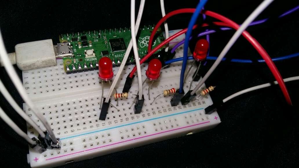
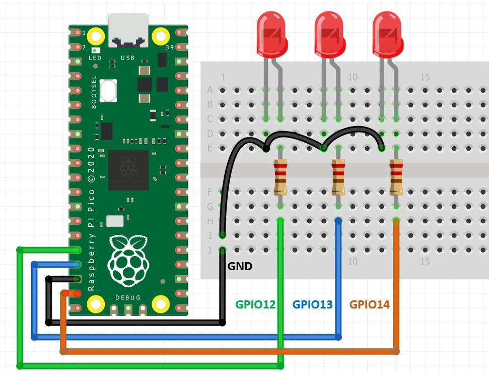
Connect the components as shown in the schematic diagram below. Each LED’s anode is connected to a different GPIO pin (GP12, GP13, GP14) through its own 220-ohm current limiting resistor, and all cathodes are connected to GND.
LED Chaser MicroPython Script
The following script creates a chasing effect where each LED turns on one at a time in sequence, creating an animated pattern. Only one LED is on at any given moment while the other two remain off.
from machine import Pin
from time import sleep

led_12 = Pin(12, Pin.OUT)
led_13 = Pin(13, Pin.OUT)
led_14 = Pin(14, Pin.OUT)

while True:
  led_12.value(0)
  led_13.value(1)
  led_14.value(0)
  sleep(0.5)
  led_12.value(1)
  led_13.value(0)
  led_14.value(0)
  sleep(0.5)
  led_12.value(0)
  led_13.value(0)
  led_14.value(1)
  sleep(0.5)
In this code, we create three separate Pin objects for GPIO12, GPIO13, and GPIO14, each configured as an output. Inside the infinite loop, we turn on one LED at a time while keeping the other two off. The 0.5-second delay between each state change creates the chasing effect. The sequence is: LED on GPIO13 turns on first, then LED on GPIO12, and finally LED on GPIO14, before the pattern repeats.
Save this code as a new file in Thonny IDE and upload it to your Raspberry Pi Pico board to see the LED chaser in action.
LED Chaser Using a List (Scalable Method)
If you want to scale the LED chaser to more LEDs, creating individual variables for each LED becomes impractical. A better approach is to use a Python list to store the Pin objects and iterate through them using a loop. This makes the code cleaner, more efficient, and easy to scale to any number of LEDs.
from machine import Pin
from time import sleep

# Define LED pins in a list
led_pins = [12, 13, 14]
leds = [Pin(pin, Pin.OUT) for pin in led_pins]

while True:
    for i in range(len(leds)):
        # Turn off all LEDs
        for led in leds:
            led.value(0)
        # Turn on only the current LED
        leds[i].value(1)
        sleep(0.3)
This approach uses a list comprehension to create Pin objects for all three LEDs at once. Inside the loop, we first turn off all LEDs and then turn on only the current one in the sequence. To add more LEDs, simply add their GPIO pin numbers to the led_pins list without modifying the rest of the code.
Troubleshooting Common Issues
If your LED is not blinking as expected, check the following common issues:
LED does not turn on at all: Verify that the LED is connected with the correct polarity. The longer leg (anode) should be connected to the GPIO pin through the resistor, and the shorter leg (cathode) should be connected to GND. Also check that the resistor value is not too high (anything above 1K ohm may make the LED too dim to see).
Script does not run: Make sure you have selected the correct interpreter in Thonny IDE. Click on the interpreter name at the bottom right of the Thonny window and select “MicroPython (Raspberry Pi Pico).” If the Pico is not detected, try unplugging and reconnecting the USB cable.
LED stays on permanently: If the LED turns on but does not blink, check that your code includes the time.sleep() calls and that you have properly indented the code inside the while True: loop. In Python, indentation is critical for defining code blocks.
Wrong GPIO pin: Double-check that the GPIO pin number in your code matches the physical pin you have connected the LED to. Remember that GPIO numbers are different from physical pin numbers on the board. Refer to the pinout diagram above to confirm the correct GPIO number.
Stopping a running script: If you need to stop a running script on the Pico, press the Stop button in Thonny IDE or press Ctrl+C in the Shell terminal to interrupt the execution.
Conclusion
In this tutorial, we learned how to use the GPIO pins of Raspberry Pi Pico as digital outputs using MicroPython. We covered the fundamentals of GPIO pins, their configuration in MicroPython using the Pin class, and demonstrated three practical examples: a single LED blink using value(), an alternate method using on()/off() and toggle() methods, and a three-LED chaser effect. We also explored a scalable list-based approach for controlling multiple LEDs efficiently. These foundational concepts will serve as a building block for more advanced Raspberry Pi Pico projects involving sensors, displays, and other peripherals.
You may also like to read:
I am trying to use the piSquared which I understand as a pico deritive. I get an error when I try to use “from machine import Pin”. The error that I’m getting is “ImportError: can’t import name pin”. I also tried to po BUT GET THE SAME ERROR.
any help would be appreciated.