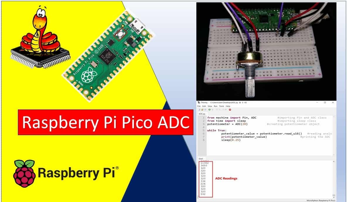
In this tutorial, we will learn how to use the ADC (Analog to Digital Converter) of the Raspberry Pi Pico using MicroPython. We will learn to read analog values from the ADC module of the Raspberry Pi Pico using both Thonny IDE and uPyCraft IDE. To provide an analog signal to the ADC channel, we will interface a potentiometer with the Raspberry Pi Pico board and read its analog value. We will also cover how to convert the raw ADC reading back into a meaningful voltage value in volts.
Recommended Components
The following components are used in this project or are helpful for getting started with Raspberry Pi Pico development.
| Component | How it’s used in this project | Buy on Amazon |
|---|---|---|
| Raspberry Pi Pico | The RP2040 microcontroller board used in this tutorial. | Check Price |
| Potentiometer (10k) | Variable resistor providing the analog input voltage to the ADC. | Check Price |
| Breadboard | Solderless breadboard for building the circuit. | Check Price |
| Jumper Wires | Male-to-male / male-to-female wires for the connections. | Check Price |
As an Amazon Associate we earn from qualifying purchases. Prices and availability are accurate as of the date/time indicated and are subject to change.
ADC Raspberry Pi Pico Prerequisites
Before starting this tutorial, make sure you have the latest version of Python 3 installed on your system and have set up MicroPython on your Raspberry Pi Pico. You should also have a working Integrated Development Environment (IDE) for programming. We will be using Thonny IDE, as we have done in our previous tutorials on blinking and chasing LEDs with MicroPython:
If you prefer uPyCraft IDE, you can check out this getting started guide instead:
What is an ADC (Analog to Digital Converter)?
An Analog to Digital Converter (ADC) is a peripheral that converts a continuous analog voltage signal into a discrete digital number that a microcontroller can process. In the real world, most physical signals — such as temperature, light intensity, sound, and pressure — are analog in nature. Sensors that measure these quantities typically produce a voltage output that varies continuously. Since microcontrollers operate on binary digital data (0s and 1s), an ADC is essential for bridging the gap between the analog world and the digital microcontroller.
For example, if you connect a temperature sensor to the Raspberry Pi Pico, it will output a voltage that varies with temperature. The ADC converts that varying voltage into a digital number that the Pico’s processor can then use in calculations or comparisons. Without an ADC, the Pico would have no way to understand or interpret such analog sensor outputs.
Raspberry Pi Pico ADC Channels
The Raspberry Pi Pico is built around the RP2040 microcontroller, which includes a 12-bit SAR-based ADC with five input channels. However, only three of these channels are exposed on the Pico’s pinout for external use. The fourth channel is internally connected to the built-in temperature sensor, and the fifth is connected to the VSYS/3 voltage divider for monitoring the supply voltage.
The three externally accessible ADC channels are mapped to the following GPIO pins:
| ADC Channel | GPIO Pin | Notes |
|---|---|---|
| ADC0 | GP26 | General purpose analog input |
| ADC1 | GP27 | General purpose analog input |
| ADC2 | GP28 | General purpose analog input |
| ADC3 | Internal | Connected to VSYS/3 for supply voltage monitoring |
| ADC4 | Internal | Connected to built-in temperature sensor |

The ADC on the RP2040 supports multiple operating modes including polling, interrupt-driven, and FIFO with DMA. The DMA mode is particularly useful for continuous, high-speed data acquisition because it allows the ADC to automatically transfer samples to memory without CPU intervention, freeing up the processor for other tasks.
The ADC conversion speed is 2 µs per sample, which equals 500 kS/s (kilo-samples per second). This is because the RP2040 operates the ADC on a 48 MHz clock derived from the USB PLL, and the ADC requires 96 clock cycles to complete one conversion:
96 cycles × (1 / 48 MHz) = 2 µs per sample (500 kS/s)Raspberry Pi Pico ADC Resolution
ADC resolution refers to the smallest change in input voltage that the ADC can detect and represent as a change in the digital output value. It is determined by the number of bits used to represent the output. The more bits an ADC has, the finer the granularity of its output and the more precise the voltage measurement.
The Raspberry Pi Pico features a 12-bit SAR (Successive Approximation Register) type ADC. This means the digital output value ranges from 0 to 4095 (which is 2¹² − 1). A reading of 0 corresponds to 0V at the input, and a reading of 4095 corresponds to the full reference voltage of 3.3V. Any voltage between these two extremes will produce a proportionally scaled digital value.
The ADC resolution voltage step can be calculated as follows:
Resolution = (Operating Voltage of ADC) / 2^(Number of ADC Bits)
Resolution = 3.3V / 2^12 = 3.3 / 4096 ≈ 0.8 mV
This means that for every 0.8 mV increase at the ADC input pin, the digital output value increments by 1. Applying the full 3.3V to the ADC input pin will yield the maximum digital output of 4095.
It is worth noting that MicroPython’s read_u16() method internally scales the native 12-bit ADC result to a 16-bit value (0–65535). This provides a consistent interface regardless of the underlying ADC hardware resolution. The actual hardware still performs a 12-bit conversion; the value is simply left-shifted to fit a 16-bit range.
To convert a raw 16-bit ADC reading back to voltage, multiply it by the ratio of the reference voltage to the full 16-bit range:
Voltage = ADC_Value × (3.3 / 65535)
For example, if the ADC returns a value of 45000:
Voltage = 45000 × (3.3 / 65535) ≈ 2.27V
Note: The Raspberry Pi Pico can only safely measure voltages between 0V and 3.3V on its ADC pins. Applying a voltage higher than 3.3V will damage the RP2040. To measure higher voltages — such as 5V, 12V, or AC voltages — you must use a voltage divider circuit or a signal conditioning module to scale the input voltage down to within the 0–3.3V range before connecting it to the ADC pin.
Reading Analog Inputs with Raspberry Pi Pico using MicroPython
We will now learn how to read analog inputs from the Raspberry Pi Pico using a potentiometer as an analog signal source. A potentiometer is a variable resistor with three terminals. When connected to a supply voltage and ground, its wiper (center terminal) outputs a voltage that varies between 0V and the supply voltage as you rotate its knob. This makes it an ideal component for testing ADC functionality.
The following diagram shows the physical connections of a typical potentiometer. The center (wiper) terminal provides the variable output voltage, while the two outer terminals are connected to VCC and GND respectively:
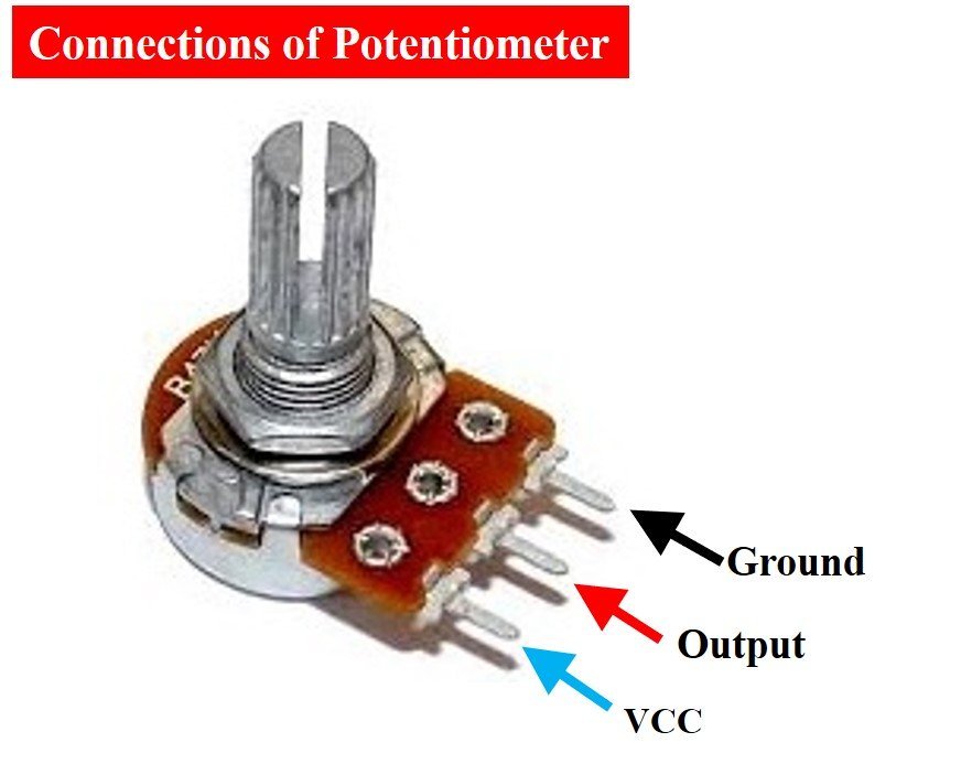
By rotating the potentiometer knob, you can supply a variable input voltage ranging from 0V to 3.3V to the ADC pin of the Raspberry Pi Pico. The ADC will then convert this voltage into a corresponding digital value, which we will read and display using MicroPython.
Required Components:
- Raspberry Pi Pico
- Breadboard
- Potentiometer (any value between 1 kΩ and 100 kΩ works fine)
- Connecting wires (jumper wires)
Raspberry Pi Pico ADC Connection Diagram
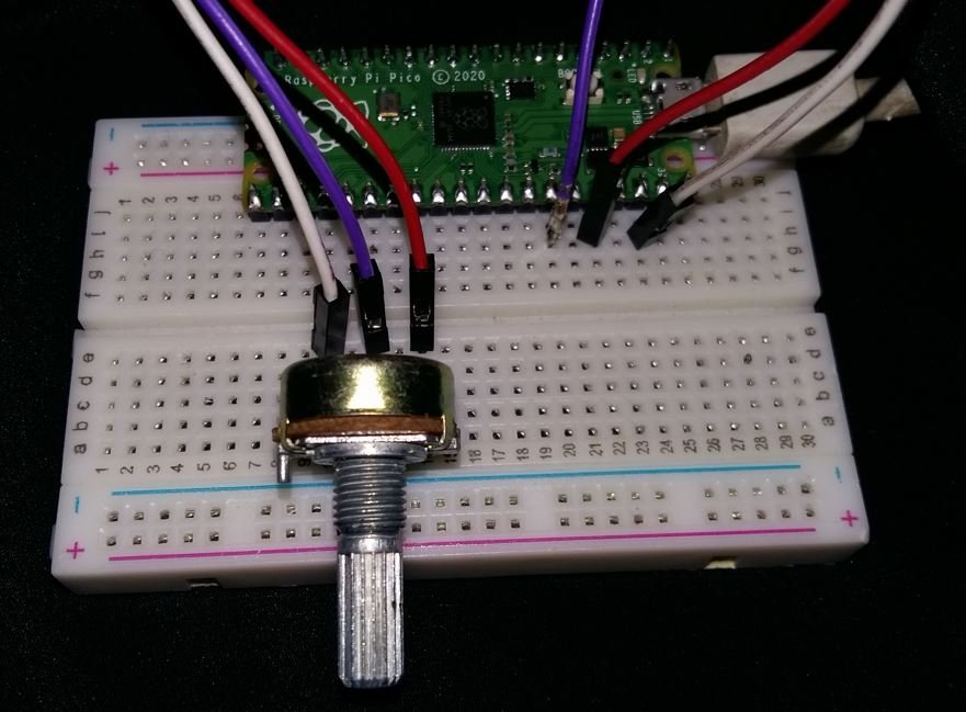
The schematic below shows how to wire the potentiometer to the Raspberry Pi Pico. Assemble your circuit as follows:
- Connect one outer terminal of the potentiometer to the 3.3V pin of the Raspberry Pi Pico.
- Connect the other outer terminal to a GND pin on the Pico. For better analog accuracy, use the AGND (Analog Ground, Pin 33) rather than a regular digital GND pin.
- Connect the center (wiper) terminal of the potentiometer to GP28 (ADC2) on the Pico.

As shown in the diagram, one terminal of the potentiometer is powered by the 3.3V output of the Pico, the center wiper terminal is connected to the analog input pin GP28, and the remaining terminal is connected to ground.
MicroPython ADC Library
MicroPython provides a built-in ADC class in the machine module that makes it straightforward to use the ADC peripheral on the Raspberry Pi Pico. Using this library involves three simple steps:
Step 1 – Import the ADC class:
from machine import ADCStep 2 – Create an ADC object for the desired pin:
You create an ADC object by passing the GPIO pin number (or a Pin object) to the ADC constructor. For GP28, use ADC(28) or equivalently ADC(Pin(28)).
potentiometer = ADC(28)Step 3 – Read the ADC value using the read_u16() method:
The read_u16() method returns an unsigned 16-bit integer in the range 0–65535, regardless of the underlying hardware resolution. This method is the standard way to read ADC values in MicroPython and is available across all supported microcontrollers, making your code more portable.
potentiometer_value = potentiometer.read_u16()ADC MicroPython Script
The following MicroPython script continuously reads the analog value from the potentiometer connected to GP28 and prints it to the serial console every 250 milliseconds:
from machine import Pin, ADC            # Importing Pin and ADC classes
from time import sleep                  # Importing sleep function

potentiometer = ADC(28)                 # Creating ADC object on GP28

while True:
    potentiometer_value = potentiometer.read_u16()   # Reading analog pin
    print(potentiometer_value)                        # Printing the ADC value
    sleep(0.25)                                       # Delay of 250ms
How Does the Code Work?
Let’s go through the code step by step to understand how it works.
First, we import the necessary classes. The ADC class is used to access the ADC peripheral, and the Pin class is used to interact with GPIO pins. Both are available from the machine module, which provides direct access to the hardware on MicroPython-compatible boards. The sleep function from the time module is used to introduce a delay between readings.
from machine import Pin, ADC
from time import sleep
Create an ADC Object for the Raspberry Pi Pico
Next, we create an ADC object named potentiometer by passing the GPIO number 28 to the ADC constructor. This tells MicroPython that GP28 will be used as the analog input pin. Internally, the Pico configures GP28 as an ADC input and prepares the hardware for sampling.
potentiometer = ADC(28)Reading the Digital Value
Inside the infinite while True loop, the code reads the analog value from the potentiometer on every iteration. The read_u16() method samples the ADC and returns a 16-bit unsigned integer between 0 and 65535. The result is stored in the variable potentiometer_value.
potentiometer_value = potentiometer.read_u16()The value is then printed to the Thonny IDE shell console, followed by a 250-millisecond delay before the next reading. This delay prevents the console from being flooded with data and makes the output easier to observe.
print(potentiometer_value)
sleep(0.25)
MicroPython ADC Code Demo
Now let’s upload and run this code on the Raspberry Pi Pico using Thonny IDE. Follow these steps:
- Open Thonny IDE and create a new file by clicking File > New.
- Copy and paste the code into the new untitled editor window.
- Click the Save icon. You will be prompted to choose whether to save the file on your computer or directly on the Raspberry Pi Pico. Save it to your computer for now. Name the file
adc_read.py(any name ending in.pywill work). - Make sure the correct board is selected in the bottom-right corner of Thonny IDE (it should show something like “MicroPython (Raspberry Pi Pico)”).
- Click the Run button (the green play icon) to execute the code on the Pico.
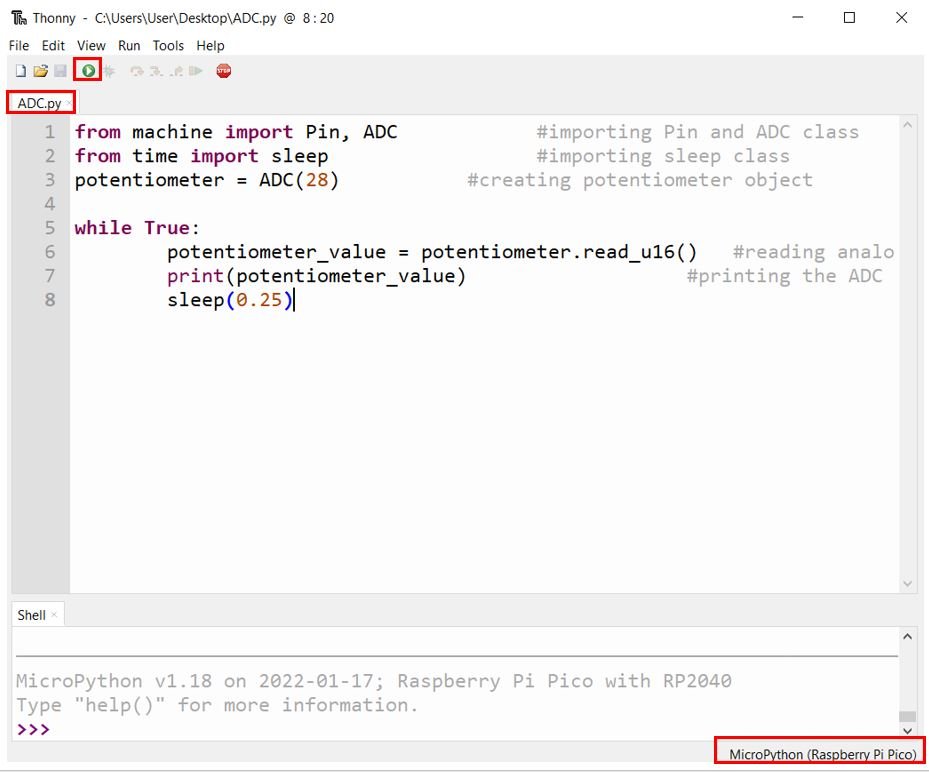
Once the code is running, rotate the potentiometer knob slowly. You should see the ADC values changing in the shell console at the bottom of Thonny IDE. When the knob is turned to one extreme, the value will be close to 0. When turned to the other extreme, it will be close to 65535.

Analog Voltage Measurement with Raspberry Pi Pico using MicroPython
In the previous section, we learned how to read raw ADC values from the potentiometer. While those numbers are useful internally, in many real-world applications you will need to know the actual voltage at the ADC pin. We can convert the raw 16-bit ADC reading back into a voltage value in volts by multiplying it by the ratio of the reference voltage (3.3V) to the maximum 16-bit value (65535).
The conversion formula is:
Voltage (V) = ADC_Value × (3.3 / 65535)
Analog Voltage Measurement MicroPython Script
The following script reads the raw ADC value and immediately converts it to a voltage before printing it to the console:
from machine import Pin, ADC            # Importing Pin and ADC classes
from time import sleep                  # Importing sleep function

potentiometer = ADC(28)                 # Creating ADC object on GP28

while True:
    potentiometer_value = potentiometer.read_u16() * 3.3 / 65535  # Convert to voltage
    print("{:.4f} V".format(potentiometer_value))                  # Print formatted voltage
    sleep(0.25)                                                     # Delay of 250ms
Upload this code to your Raspberry Pi Pico and open the shell console. As you rotate the potentiometer, you will now see the actual voltage value displayed instead of a raw integer. When the knob is at the minimum position, the value will be near 0.0000 V, and at the maximum position it will be close to 3.3000 V.
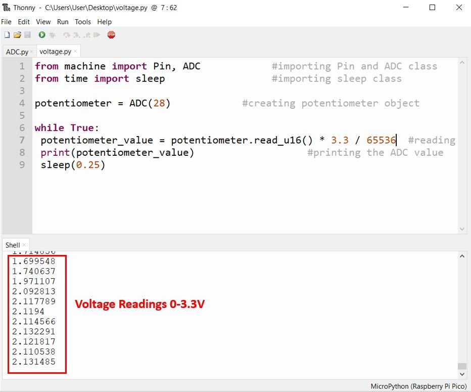
The key line responsible for the conversion is:
potentiometer_value = potentiometer.read_u16() * 3.3 / 65535This multiplies the raw 16-bit reading by 3.3 / 65535, which gives the voltage in volts as a floating-point number. We also used Python’s str.format() method with :.4f formatting to display the result to four decimal places, which looks cleaner in the console output.
Improving ADC Accuracy and Reducing Noise
In practice, you may notice that consecutive ADC readings from the same input vary slightly even when the potentiometer is not moving. This is normal behavior and is caused by ADC noise. The RP2040’s ADC reference voltage is derived from the 3.3V supply rail, which can contain small amounts of ripple from the onboard voltage regulator. This instability in the reference voltage directly affects the accuracy of ADC readings.
Here are a few practical tips to improve ADC measurement accuracy:
- Use AGND instead of GND: The Raspberry Pi Pico has a dedicated Analog Ground pin (AGND, pin 33). For ADC circuits, connect the ground of your analog components to AGND rather than a regular GND pin. This helps reduce digital switching noise coupling into the analog ground reference.
- Add a decoupling capacitor: Placing a 100 nF ceramic capacitor between the ADC input pin and AGND can help filter out high-frequency noise. For high-impedance sources such as potentiometers, a larger capacitor (1 µF to 10 µF) may provide further improvement.
- Average multiple readings: Take multiple samples in rapid succession and compute their average. This technique, known as oversampling, is effective at reducing random noise. Taking 16 samples and averaging them will significantly smooth out the output.
- Use an accurate reference voltage: The built-in 3.3V rail may not be perfectly precise. For critical measurements, you can measure the actual 3.3V output with a calibrated multimeter and use that measured value in your conversion formula instead of the nominal 3.3V.
Here is an example of implementing averaging in MicroPython to get more stable readings:
from machine import ADC
from time import sleep

potentiometer = ADC(28)

def read_averaged(adc, samples=16):
    total = 0
    for _ in range(samples):
        total += adc.read_u16()
    return total / samples

while True:
    avg_value = read_averaged(potentiometer)
    voltage = avg_value * 3.3 / 65535
    print("{:.4f} V".format(voltage))
    sleep(0.5)
In this example, the read_averaged() function takes 16 ADC samples and returns their average. This averaging significantly reduces noise and produces much more stable voltage readings compared to a single sample.
Reading the Internal Temperature Sensor using ADC
As mentioned earlier, the Raspberry Pi Pico has a built-in temperature sensor connected to ADC channel 4 (ADC4). You can read this sensor directly through MicroPython without any additional hardware. This is useful for monitoring the chip temperature or for simple thermal management in your projects.
To access the internal temperature sensor in MicroPython on the Pico, use ADC(4):
from machine import ADC
from time import sleep

temp_sensor = ADC(4)               # Connect to internal temperature sensor

def read_temperature():
    raw = temp_sensor.read_u16()
    voltage = raw * 3.3 / 65535
    # Formula from the RP2040 datasheet
    temperature = 27 - (voltage - 0.706) / 0.001721
    return temperature

while True:
    temp = read_temperature()
    print("Temperature: {:.2f} C".format(temp))
    sleep(1)
The temperature conversion formula used here (27 - (voltage - 0.706) / 0.001721) comes directly from the RP2040 datasheet. The typical output voltage of the temperature sensor is 0.706V at 27°C, with a slope of approximately −1.721 mV/°C. Note that this built-in sensor is not highly accurate — it should be considered an approximation suitable for monitoring trends rather than precise temperature measurement.
Conclusion
In this tutorial, we covered how to use the ADC (Analog to Digital Converter) of the Raspberry Pi Pico with MicroPython. We explained the fundamentals of ADC operation, the ADC channels available on the Pico, how to calculate resolution and convert raw ADC readings to voltage, and how to wire a potentiometer to the Pico for analog input. We also demonstrated how to improve ADC accuracy by averaging multiple samples, and how to read the built-in temperature sensor using ADC4.
You can further extend this knowledge to measure higher voltages such as AC or DC signals above 3.3V by using an appropriate voltage divider or signal conditioning circuit. The ADC is a fundamental building block in countless embedded projects, from battery monitoring and sensor interfaces to audio processing and environmental control systems.
You may also like to read these related tutorials:
How is the code for programming the Pico with the help of the Arduino IDE?
I think to reduce the impact of potential interference you should use AGND (pin 33) instead of GND (pin 38)
Thanks for the suggestion – it does seem to make a small improvement. I’m using a small 10 kohm, 12 turn Bourns potentiometer with the wiper connected to GP26/ADC0, and a 100pf cap from the wiper to ground. I’m running a slightly-modified version of the `hello-adc` example from the C SDK.
Initially, I was amazed at how much variance I was getting from consecutive readings. Adding the 100pf cap smoothed the variance a bit, and your suggestion for AGND has smoothed the readings a bit more.
Just watching the numbers go by now, I see this range over 15-20 measurements:
1.025610 – .993384 ~ 32 mV
This is 40 units of ADC resolution (0.8 mV) – that still seems a bit much.
The potentiometer is a high impedance and so the sampling current from the SAR ADC has a huge impact. A much larger cap, with short leads should help.
It’s unfortunate the ADC can’t use an external voltage reference, since the 3.3V is pretty noisy and poorly regulated.
I take 1000 readings and average them, I then have to multiply the voltage reading by 0.95 to get it to correspond to the multimeter.
I know this is old but but Im having to do the same with the .95
except I have to divide.
battery.read_u16() * 3.3 / 65536 *2 /.95
The *2 is because I have the battery feeding the input (28) through a voltage divider. Do you know why you have to use the .95?
In reply to Paulk
If you have a accurate voltmeter measure the 3.3V reference and use this reading in place of the 3.3 in your code.
This should give more accurate readings for anyone.
The pico 3.3v will vary quite a few ADC bits with each different Pico.
while True:
rvdc=machine.ADC(26).read_u16()
print(rvdc,” “,end=””)