In this ESP32 tutorial, we will interface DS3231 RTC Real Time Clock module with ESP32 which used to get current time. We will display RTC values on an OLED. We will build a Real Time Clock (RTC) with the help of DS3231 module, ESP32 and OLED display. A real time clock is basically a digital clock which is responsible for keeping track of accurate time in terms of hours, minutes, seconds, months, days and sometimes even years. They are helpful and used in situations where low power mode is used. There are many RTCs available in the market such as DS3221 and DS1307 which usually consist of a controller, oscillator, and an embedded quartz crystal resonator. In this user guide, we will focus on DS3231 RTC module and program it with ESP32 in Arduino IDE to create a Real Time Clock.
We have a similar guide with ESP8266 NodeMCU:
Recommended Components
The following components are used in this project or are helpful for building it with the ESP32.
| Component | How it’s used in this project | Buy on Amazon |
|---|---|---|
| ESP32 Development Board | The main controller that reads the date and time from the RTC over I2C and drives the OLED. | Check Price |
| Micro USB Cable | Connects the ESP32 to your computer for uploading code and powering the board. | Check Price |
| Breadboard | Provides a solderless base to wire the ESP32, RTC module and OLED together. | Check Price |
| Jumper Wires | Used to make the SDA, SCL, power and ground connections between the devices. | Check Price |
| 0.96″ SSD1306 OLED Display | Displays the current date, day and time read from the DS3231 RTC module. | Check Price |
As an Amazon Associate we earn from qualifying purchases. Prices and availability are accurate as of the date/time indicated and are subject to change.
DS3231 Precision RTC Module
The DS3231 precision RTC module is one of the most commonly used RTC module which keeps track of the current data and time. It is used in electronics projects for time keeping, data logging, building clocks, timers etc. This module runs on the DS3231S RTC chip and also contains the AT24C32 EEPRROM for accurate time keeping. It has a very accurate real time clock which houses an integrated temperature compensated crystal oscillator and crystal. Additionally, due to the presence of the crystal resonator, the DS3231 module gives more accurate time keeping results in the long run.
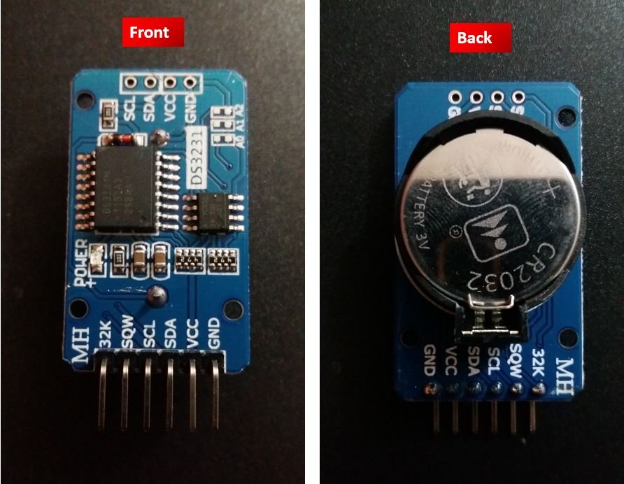
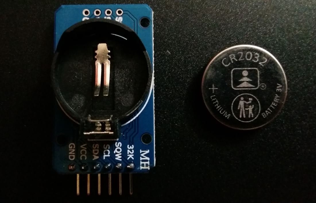
One of the interesting features of this RTC module is that it consists of a CR2032 battery holder where a 20mm 3V Lithium coin cell is inserted. Therefore, even if the power supply to the module is cut off, it will still keep track of the data and time. Once the timekeeping is started, it will always be maintained.
The diagram below shows the backside of the module which consists of the CR2032 battery holder and the coin cell respectively.
DS3231 RTC Module Pinout
The DS3231 is a low cost RTC module that communicates with the microcontroller using I2C communication protocol. Let us look at the pinout of the DS3231 precision RTC module.
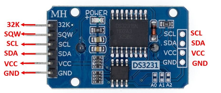
| 33K | This is the output pin which gives the compensated temperature as well as accurate reference clock. |
| SQW | This pin outputs a square wave at different frequencies of 1Hz, 4kHz, 8kHz, or 32kHz. It may also provide an interrupt signal. |
| SCL | This is the serial clock pin which is used in I2C communication. |
| SDA | This is the serial data pin which is also used in I2C communication. |
| VCC | This is the power supply pin of the module. Connect it with 3.3V or 5V |
| GND | This is the ground pin used for providing common ground. |
Apart from these six pins, the module also features the I2C and power pins on the other side of the module to connect to another module (daisy chain).
Interfacing DS3231 Module with ESP32 and SSD1306 OLED Display

We will require the following components for this project.
- ESP32 board
- DS3231 RTC Module with Coin Cell
- SSD1306 OLED Display
- Connecting Wires
- Breadboard
As mentioned previously, the DS3231 module uses I2C communication protocol to communicate with the microcontroller. The SSD1306 OLED that we are using also has an I2C interface. Hence, we will use the same I2C pins of ESP32 to connect with both the RTC module and the OLED.
By default, the I2C pin in ESP32 for SDA is GPIO21, and for SCL is GPIO22.
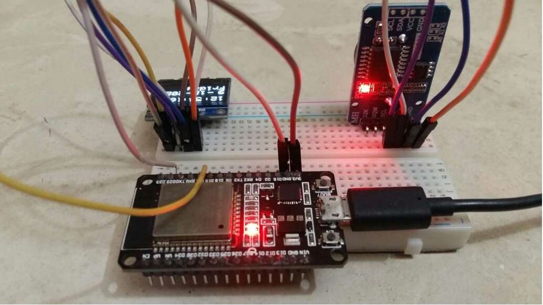
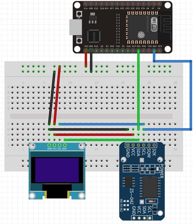
The OLED display and the RTC module both require an operating voltage in the range of 3.3-5V hence we will connect the VCC terminal with 3.3V which will be in common with the ESP32 board. SCL of the display and the RTC module will be connected with the SCL pin of ESP32. Likewise, the SDA of the display and RTC module will be connected with the SDA of ESP32. The ground of all the devices will be held common.
The connections between the three devices can be seen below:
| ESP32 board | DS3231 Module | SSD1306 OLED Display |
|---|---|---|
| 3.3V | VCC | VCC |
| GPIO21(I2C SDA) | SDA | SDA |
| GPIO22 (I2C SCL) | SCL | SCL |
| GND | GND | GND |
Follow the schematic diagram below to connect the devices.
Setting up Arduino IDE
We will use Arduino IDE to program our ESP32 development board. Thus, you should have the latest version of Arduino IDE. Additionally, you also need to install the ESP32 plugin. If your IDE does not have the plugin installed you can visit the link below:
Install RTC Library
As we are using DS3231 RTC module with ESP32, hence we will require a library while programming in Arduino IDE. We will use the RTClib by Adafruit which is a great Arduino RTC library tested for DS3231 Precision RTC, PCF8523 RTC and DS1307 RTC. Open this link which opens the GitHub page for the RTClib library. Head over to Code > Download ZIP and download the zip file.
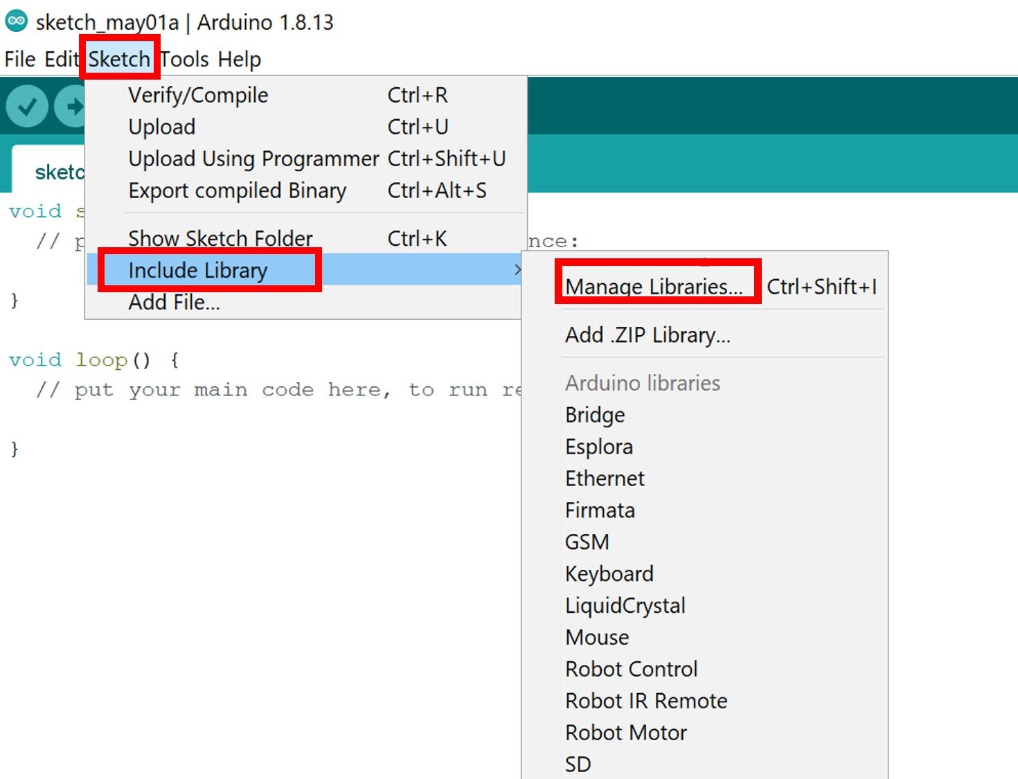
Now open Arduino IDE and go to Sketch > Include Library > Add .ZIP library and select the zip file that you just downloaded. This adds the library to your IDE.
Install SSD1306 OLED Library
To use the OLED display in our project, we have to install the Adafruit SSD 1306 library and Adafruit GFX library in Arduino IDE. Follow the steps below to successfully install them.about:blank
Open Arduino IDE and click on Sketch > Library > Manage Libraries
The following window will open up.

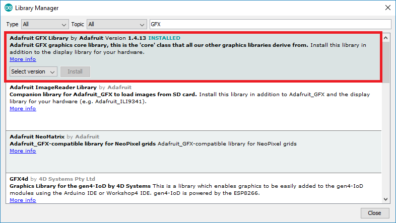
Type ‘SSD1306’ in the search tab and install the Adafruit SSD1306 OLED library.

We will also require the Adafruit GFX library which is a dependency for SSD1306. Type ‘Adafruit GFX’ in the search tab and install it as well.
After installing the libraries, restart your IDE.
ESP32 Arduino Sketch Real Time Clock with DS3231 Module
Open your Arduino IDE and go to File > New to open a new file. Copy the code given below in that file.
#include <Wire.h>
#include <Adafruit_GFX.h>
#include <Adafruit_SSD1306.h>
#include "RTClib.h"

RTC_DS3231 rtc;

char days[7][12] = {"Sunday", "Monday", "Tuesday", "Wednesday", "Thursday", "Friday", "Saturday"};

Adafruit_SSD1306 display = Adafruit_SSD1306(128, 64, &Wire, -1);

void setup() {
  Serial.begin(115200);

  display.begin(SSD1306_SWITCHCAPVCC, 0x3C);

  if (! rtc.begin()) {
    Serial.println("Could not find RTC! Check circuit.");
    while (1);
  }

  rtc.adjust(DateTime(__DATE__, __TIME__));
  display.clearDisplay();
  display.setTextColor(WHITE);
  display.setTextSize(2);
  display.setCursor(0, 20);
  display.print("RTC CLOCK");
  display.display();
  delay(5000);
}

void loop() {
  DateTime now = rtc.now();

  display.clearDisplay();
  display.setTextSize(2);
  display.setCursor(75, 0);
  display.println(now.second(), DEC);
  display.setTextSize(2);
  display.setCursor(25, 0);
  display.println(":");
  display.setTextSize(2);
  display.setCursor(65, 0);
  display.println(":");
  display.setTextSize(2);
  display.setCursor(40, 0);
  display.println(now.minute(), DEC);
  display.setTextSize(2);
  display.setCursor(0, 0);
  display.println(now.hour(), DEC);
  display.setTextSize(2);
  display.setCursor(0, 25);
  display.println(now.day(), DEC);
  display.print(days[now.dayOfTheWeek()]);
  display.setTextSize(2);
  display.setCursor(20, 25);
  display.println("-");
  display.setTextSize(2);
  display.setCursor(35, 25);
  display.println(now.month(), DEC);
  display.setTextSize(2);
  display.setCursor(60, 25);
  display.println("-");
  display.setTextSize(2);
  display.setCursor(75, 25);
  display.println(now.year(), DEC);
  display.display();
}
How the Code Works?
We will start off by including the necessary libraries for this project. Wire.h will allow us to communicate through the I2C protocol. Whereas the OLED libraries are the ones which we previously installed and are required for the proper functionality of the OLED display. The RTClib.h will help us access functions to build the RTC.
#include <Wire.h>
#include <Adafruit_GFX.h>
#include <Adafruit_SSD1306.h>
#include "RTClib.h"
Next create an object of RTC_DS3231 called ‘rtc.’
RTC_DS3231 rtc;Also, create a 2d array of characters called ‘days’ that holds the days of the week.
char days[7][12] = {"Sunday", "Monday", "Tuesday", "Wednesday", "Thursday", "Friday", "Saturday"};Then, we will initialize the OLED display by creating an object of Adafruit_SSD1306 and specifying the width, height, I2C instance (&Wire), and -1 as parameters inside it.’ -1′ specifies that the OLED display which we are using does not have a RESET pin. If you are using the RESET pin then specify the GPIO through which you are connecting it with your development board.
Adafruit_SSD1306 display = Adafruit_SSD1306(128, 64, &Wire, -1);setup()
Inside our setup() function, we will initialize the serial communication at a baud rate of 112500.
Serial.begin(115200); Moreover, we will also initialize the OLED display and the RTC module by using display.begin() and rtc.begin() respectively. Make sure you specify the correct address of your OLED display. In our case, it is 0X3C.
  display.begin(SSD1306_SWITCHCAPVCC, 0x3C);

  if (! rtc.begin()) {
    Serial.println("Could not find RTC! Check circuit.");
    while (1);
  }
After that we call rtc.adjust(DateTime(DATE, TIME)) function. This function is responsible for aligning the time according to our computer.
rtc.adjust(DateTime(__DATE__, __TIME__));Then, we will clear the buffer by using clearDisplay() on the Adafruit_SSD1306 object.
First, we will set the size of the text using setTextSize() and pass the size as a parameter inside it. Next, we will control the color of the text by using the setTextColor() function and passing WHITE as an argument. We will use the setCursor() function to denote the x and the y axis position from where the text should start. Then we print the text ‘RTC CLOCK’ on the display for 5 seconds using display.print().
  display.clearDisplay();
  display.setTextColor(WHITE);
  display.setTextSize(2);
  display.setCursor(0, 20);
  display.print("RTC CLOCK");
  display.display();
  delay(5000);
loop()
Inside the loop() function, we acquire the current date and time using rtc.now() and save it in the variable DateTime now.
DateTime now = rtc.now();Then, we display the time in HH:MM:SS along with the day, date, month and year on the OLED. This is achieved by first clearing the display, setting the text size, setting the cursor position and then printing the text using display.println().
  display.clearDisplay();
  display.setTextSize(2);
  display.setCursor(75, 0);
  display.println(now.second(), DEC);
  display.setTextSize(2);
  display.setCursor(25, 0);
  display.println(":");
  display.setTextSize(2);
  display.setCursor(65, 0);
  display.println(":");
  display.setTextSize(2);
  display.setCursor(40, 0);
  display.println(now.minute(), DEC);
  display.setTextSize(2);
  display.setCursor(0, 0);
  display.println(now.hour(), DEC);
  display.setTextSize(2);
  display.setCursor(0, 25);
  display.println(now.day(), DEC);
  display.print(days[now.dayOfTheWeek()]);
  display.setTextSize(2);
  display.setCursor(20, 25);
  display.println("-");
  display.setTextSize(2);
  display.setCursor(35, 25);
  display.println(now.month(), DEC);
  display.setTextSize(2);
  display.setCursor(60, 25);
  display.println("-");
  display.setTextSize(2);
  display.setCursor(75, 25);
  display.println(now.year(), DEC);
  display.display();
Demonstration
Choose the correct board and COM port before uploading your code to the board. Therefore go to Tools > Board and select ESP32 Dev Module.
Select the ESP32 Dev module as follows:
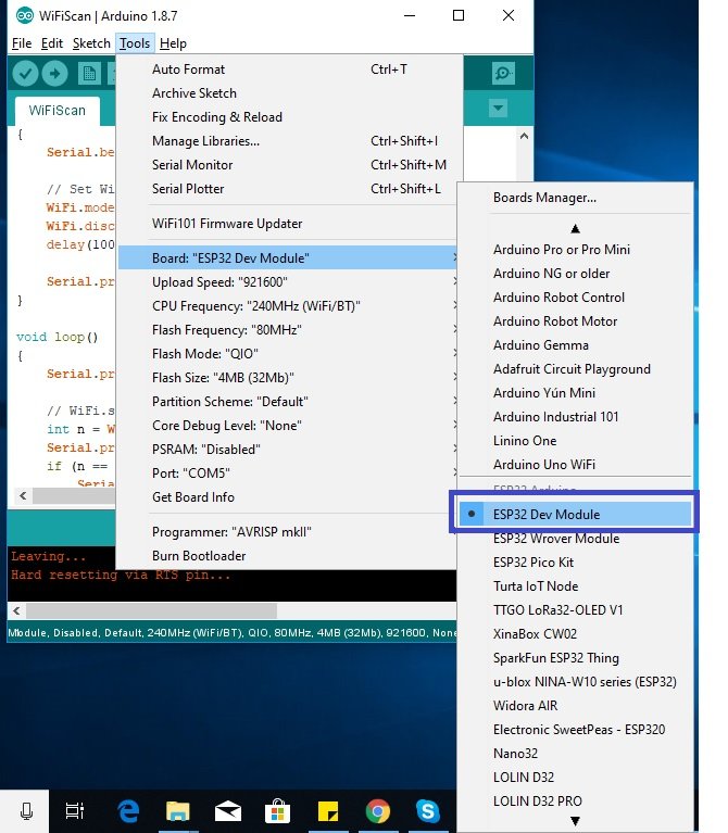
Then, go to Tools > Port and select the appropriate port through which your board is connected.

Click on the upload button to upload the code to ESP32 development board.
After you have uploaded your code to the ESP32, press its ENABLE button.

The OLED will start displaying the current time and date.

Video Demo
You may also like to read:
- ESP32 Real Time Clock (RTC) using DS1307 Module and display on OLED
- IoT Based Analog and Digital Clock using OLED and ESP32/ESP8266
- Internet Based Digital Clock using ESP32 and MAX7219 Dot Matrix Display
- Interface DS1307 RTC Module with Arduino – Display Date/Time on OLED
- Digital clock ds1307 using PIC microcontroller
- Interface DS3231 RTC Module with Arduino – Set/Read Date and Time
very nice with just 1 exeption,you used a clock for a clock,in case you didn’t know,the core of an esp32 is an RTC,built in it,so,using an RTC for esp32…you get the ideea,not to mention that the internal RTC of an esp32 is more exact than that RTC that you are using.