In this tutorial, we will discuss the hall effect sensor. In order to check the practical behavior of any electrical or electronic equipment, it is very necessary to install the device that communicates between this electrical or electronic equipment and our real-time system. For this purpose, there are so many sensors and transducers available on the market that have different uses. One such sensor is known as a hall effect sensor, which we will talk about in this article.
Introduction to Hall Effect Sensors
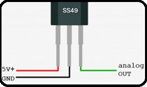
A hall effect sensor is the type of sensor that is typically useful for detecting the practical behavior of anything, such as a motor, in response to a changing magnetic field. These are basically transducers whose voltages vary with changing magnetic fields. This sensor consists of a metal strip. When we place it inside any magnetic field, the presence of this magnetic field electron deflects towards the edges of this strip. Hence, this induces EMS across its edges. In simple words, it just works like an analog transducer. They have applications in speed detection, approximate switching, current sensing, and positioning sensing. In the figure below, we can see a simple hall effect sensor with three terminals.
Working Principle
The working principle of this sensor is very simple. It actually consists of a current-carrying metal strip. When this current-carrying metal strip is inside any transverse magnetic field, it develops EMF across its edges. The magnitude of this EMF depends on the density of the flux and the mobility of electrons. This property of this current-carrying conductor is called the hall effect. This hall effect element is typically useful for sensing current and magnetic field measurements.

Circuit Diagram
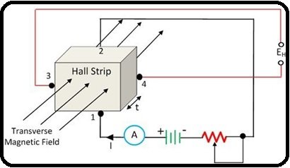
For a hall effect element circuit, refer to the figure below.
Explanation
According to the circuit, when we apply current to terminals 1 and 3, we acquire an output at terminals 3 and 4. When there is no magnetic field, terminals 3 and 4 remain at the same potential. Hence, there is no changeor effect on the hall effect strip. Similarly, when we apply the magnetic field to the hall effect strip, it induces EMF or voltages across terminals 3 and 4. These voltages are directly proportional to the material strength that has been used for hall effect strips. These output voltages are obtainable by the following equation:
EH = KHIB/t (1)
Where KH is the hall effect co-efficient, we can obtain this from equation 2.
KH = v-m/A-wbm-2 (2)
Where KH is the hall effect coefficient, I is the current, B is the flux density in Wbm-2, and t is the thickness of the strip.
It is easy to measure the output voltages, current, and magnetic field strength, but measuring the hall effect EMF in a simple conductor is very difficult because it is very small. Instead of a simple conductor, if we use the germanium conductor, then its hall effect EMF is easily measurable with the help of a moving coil instrument.
Types of Hall Effect Sensors
To make the hall effect sensor’s output usable, it requires a signal conditioning circuit. This circuit does the temperature compensation, amplification, linearity, voltage regulation, etc. Currently, two types of sensors are in use: the first is an analog output hall effect sensor, and the second is a bi-level or digital output hall effect sensor.
Analogue Hall Effect Sensor
If we compare this sensor with a basic type, then this has more stable behavior in noisy environments and has a large voltage range to operate. This provides an analog output voltage that is proportional to the magnetic field. We can see an analog hall effect sensor circuit in the figure below.

In this circuit, the differential amplifier provides fixed offset or biased voltages. So that when there is no magnetic field, these voltages appear across the output terminals of this circuit. These voltages are the null voltages. At hall effect terminals, the magnetic field could be positive or negative. When the magnetic field is positive, output voltages increase the null-value voltages. Similarly, when the magnetic field is negative, output voltages decrease the null-value voltages. These sensors are not so accurate with magnetic fields. Therefore, they require proper calibration in places where there is a need for high-precision measurements. The flexibility of this sensor increases by adding an open emitter or open collector push-pull transistor at the output side of the differential amplifier.
Digital Output Hall Effect Sensor
This type of sensor has a digital output that means ON or OFF; therefore, we also call it a bi-level hall effect sensor. This sensor is almost the same as an analog sensor, but the only difference is that it has a Schmitt trigger. In this Schmitt trigger, a hysteresis threshold level is built in. This Schmitt-trigger addiction assembly converts the analog input into digital output after comparing the differential amplifier output with reference fixed voltages. When the differential amplifier output is greater than the reference voltages, the Schmitt trigger will turn on. Similarly, when differential amplifier output is less than the reference voltages, the Schmitt trigger will turn off. For a simple digital output hall effect sensor, refer to the figure below.

Applications of Hall Effect Sensor
Hall effect sensors have been used in different applications, and their construction depends upon their configuration. Their main applications include biomedical, automatic tellers, telecommunications, automobiles, and the process control industry.
Position Sensor
This type of hall effect sensor is useful for sensing sliding motion. In this sensor, there is a tight gap between the hall effect element and the magnet. When the magnet moves in a forward and backward direction, it produces a magnetic field. The polarity of this magnetic field is positive when the element moves toward the north pole. Similarly, the magnetic field is positive when the element moves toward the south pole. These sensors are called approximate sensors and are used for position sensing.
Brushless DC Motor Sensor
In brushless DC motors, electronic commutation controls the power distribution instead of mechanical commutation. For this purpose, three digital output hall effect sensors are installed at the stator end of a brushless DC motor, and for operating these sensors, permanent magnet materials are installed at the rotor shaft.
Current Sensor
It is the type of hall effect sensor that is useful for measuring both AC and DC currents. These are available in a range from 250 mA to a thousand amps. These are linear sensors. When we place them near a magnetic field, a voltage develops across these sensors. The values of these voltages are proportional to the magnetic field strength.
Conclusion
In conclusion, this article provides an in-depth overview of hall effect sensors. It covers the basic introduction along with the working principle, the types of sensors, and their applications to help us better understand the concept. Hopefully, this was helpful in expanding your knowledge.
You may also like to read:
- Different Types Of Renewable energy Resources
- Different Types of Fault in Three Phase Induction Motor
- What is Led matrix? Types of Dot matrix display with working
- types of oscillator used in microcontrollers
- Enumerated Data Types in LabVIEW: Tutorial 16
- Microcontroller Memory Organization and Types – Explained with Memory Segments
- Data Types in LabVIEW – Tutorial 4
This concludes today’s article. If you face any issues or difficulties, let us know in the comment section below.
Very informative, Thank U
To detect inclusion or crack on steel block by ultrasonic testing we want to
apply hall probe system with other instruments like gauss meter,R.S232, CCD Detector, spectrograph variable attenuator etc