In this tutorial we will look at an LED matrix display. Led matrix is a dot matrix of large display, low resolution value and is useful for In this tutorial, we will discuss the LED matrix. Led matrix is a dot matrix of large display and low resolution that is useful for both industrial and commercial displays as well as for hobbyist human interface machines. It contains a 2-D diode matrix with the cathode in rows and the anode in columns. In this LED matrix, we can control each LED individually by controlling the electricity through each pair of column or row diodes. These matrices are very popular because, by means of displaying information, they allow static and moving images and text. We can see an LED matrix in the figure below.

Types of LED Matrix
There are so many types of LED matrices that are available for industrial and commercial purposes. We will be discussing some of them in this article with respect to their structure.
- 8×8 dot Matrix
- 5×7 dot Matrix
- 128×16 Two lined
- 128×32 Four lined
- 128×64 Eight lined
8×8 Dot Matrix
In a dot matrix, multiple diodes are connected together in rows and columns. This is done to minimize the number of pins required to drive the dot-light-emitting diodes. Suppose in an 8×8 dot matrix there are 64 I/O pins for displaying each diode pixel. For making an 8×8 dot matrix, all the anodes connect together in rows R1 to R8, similarly the cathodes connect together in columns C1 to C8. By doing this the required number of I/O pins have reduced by 16 as we can see in the figure below:
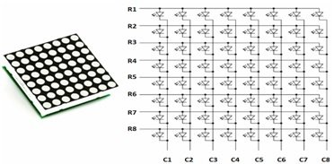
According to the figure each LED is addressable by its row and column number. If R5 is pulled high and C4 pulled low, then the LED in fifth row and fourth column would be high. Similarly, we can also display any pattern by scanning and enabling of LEDs in row and column.
5×7 Dot Matrix:
A 5×7 LED matrix has 5 rows and 7 columns of light-emitting diodes. These diodes connect together to make an LED matrix. According to the figure, if we want to display an alphabet, let’s say A. Then, first, we pull high the column C1 and pull low the other columns by blocking their ground paths. Now the C1 is pulled high, and we need to turn on the LEDs in rows R2 to R7 of this column. We do this by applying the forward bias voltage to these rows. Next, we select column C2, deselect the other column, and apply the forward bias voltage across R1 and R5, and so on.
Construction of Dot Matrix
The construction of this display is very simple. If we want to make our own prototype display, then we just need to solder the diodes on a Vero board or a premade double or single-sided board. Suppose we want to construct a prototype 8×8 dot matrix display similar to the one in Figure 2, then we will need 64 light-emitting diodes.
The positive end of one diode connects to the positive end of the other diode to make the rows. Similarly, by connecting 8 diodes in this configuration, we get a single row. Now we will repeat this process for the other 8 rows by connecting the positive end of each diode. For making the columns, the negative end of one diode connects to the negative end of the other diode. Similarly, we make 8 columns by connecting the negative end of each diode. All these diodes connect with each other through bare copper wire, and we need to solder all of them properly; otherwise, there will be no connection between them.
Dot Matrix Interfacing with Microcontroller
The dot matrix display consists of connections of LEDs in rows and columns. These can be on or off as we wish, but we can only achieve this through a microcontroller. Here we will interface PIC microcontrollers with the dot matrix. For reference, see the figure below.
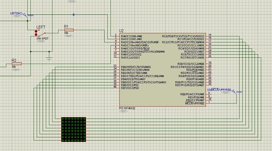
According to the figure, we can see that the microcontroller’s port pin can directly drive each row or column of the dot matrix display. For driving the column lines of the dot matrix display, the microcontroller requires an additional circuit. The AT89S51 microcontroller is a high-performance, low-power CMOS 8-bit microcontroller. This has 4 KB of programmable flash memory. This device was manufactured using Atmel’s high-density nonvolatile memory technology. This is compatible with the industry standard 80C51 instruction.
This microcontroller consists of 4 ports and 32 I/O lines. Here, the dot matrix rows connect to port 1, and the columns connect to port 2. But columns are connected with extra IC ULN2003A. This is a high-voltage (50V) high-current (500 mA per channel) Darlington-Pair transistor array. This IC has seven channels with individually clamped output diodes. This is an active high device, which means that we need to apply the high logic at the input side to make the corresponding output high. The input pins are 1B, 2B, 3B, 4B, 5B, 6B, and 7B, while the corresponding pins are 1C, 2C, 3C, 4C, 5C, 6C, and 7C. For displaying the alphabet A, we need a proper code, which we burn into the microcontroller to turn on and turn off the LEDs.
Applications of LED Matrix Display
An LED matrix display is a device that is useful for displaying information on machines, like railway departure indicators and clocks, and there are so many other devices that require a simple display of very low resolution. These displays are available in different resolutions. Here we explain the uses and applications of 2-dimensional displays on different devices.
- Television Sets
- Computer Monitors
- Head Mounted Displays
- Broadcast Reference Monitors
- Medical Monitors.
Television Sets:
The dot matrix display is used in home television sets for displaying the television viewing picture, channel view, and loud speaker view.
Computer Monitors:
The computer monitors use the dot matrix display for displaying the data, pictures, and everything else that the CPU is sending.
Head Monitor Display:
The dot matrix display is useful in head monitor display devices that are for military, government (fire, police, etc.), civilian, and commercial purposes.
Broadcast Reference Monitors:
The broadcast reference monitor, which is basically the video monitor, has these LEDs that display the different videos.
Medical Monitors:
It is useful in medical equipment that has a display facility for observing disease conditions.
Advantages
- It is more efficient because now it is capable of outputting 135 lumens per watt.
- It has long life almost 50,000 hours if properly installed.
- It is called solid-state lighting because it is made of solid-state material with no tube, no filament, and no bulb to break.
- It is friendly for the environment because it has no mercury or any other hazardous material.
- Its brightness and color can be easily controlled.
- It has no wash-out colors like other light sources, such as fluorescent lights.
- It has a low temperature, even starting at zero temperature.
Disadvantages:
- Its price per lumen is currently more expensive in comparison to the other conventional displays on the basis of capital cost.
- Its performance totally depends on the design parameters, so its design is a little bit difficult for good performance.
- When we are interfacing with a microcontroller, it requires a good engineer to write the code. This is because not everyone can write this code.
- For operating the LED, constant current and voltage are required every time, and sometimes this becomes difficult.
Conclusion
In conclusion, this article provides an in-depth overview of dot LED Matrices. It covers their introduction, types, construction, interfacing along with applications, advantages and disadvantages to help us better understand the concept. You can utilize this tutorial to choose the best LED matrix display for your project. Hopefully this was helpful in expanding your knowledge.
You may also like to read:
- MAX7219 LED Dot Matrix Display with Raspberry Pi Pico
- MAX7219 LED Dot Matrix Display with ESP8266 NodeMCU
- LED Dot Matrix Display with ESP32 and MAX7219
- Internet Based Digital Clock using ESP32 and MAX7219 Dot Matrix Display
- LED Matrix Interfacing with PIC Microcontroller
- I2C LCD interfacing with ESP32 and ESP8266 in Arduino IDE
This concludes today’s article. If you face any issues or difficulties, let us know in the comment section below.
How to read your tetorial
what way and what sftware is required?