In this tutorial, we are going to learn how to interface an LED matrix with a PIC microcontroller. A dot matrix LED displays a 2-dimensional patterned array of LEDs used to represent characters, symbols, and images. Its applications include displaying characters and alphabets where low resolution is not an issue. So, we will display some alphabets and numbers on it.
Recommended Components
The following components are used in this project or are helpful for building it with a PIC microcontroller.
| Component | How it’s used in this project | Buy on Amazon |
|---|---|---|
| PIC16F877A microcontroller | The PIC microcontroller that drives the LED dot matrix. | Check Price |
| PICkit 5 programmer/debugger | Programs and debugs the PIC microcontroller. | Check Price |
| MAX7219 LED dot matrix | The 8×8 LED matrix module driven by the MAX7219 for display. | Check Price |
| Breadboard | Solderless board to build and test the circuit. | Check Price |
| Jumper Wires | Connect the microcontroller to other components. | Check Price |
As an Amazon Associate we earn from qualifying purchases. Prices and availability are accurate as of the date/time indicated and are subject to change.
LED Matrix Introduction
LED dot matrix modules are available in various dimensions (7×5, 8×8, 7×15, etc.). An 8×8 LED matrix is shown below, which contains 8 rows and 8 columns. An LED is connected between every row and every column. Each The identification of an LED is based on its respective row and column numbers. If we provide 3.3 V to a row and connect the respective column to the ground, then only that particular LED will glow. If we have to glow an LED connected between R2 and C1 in the below picture, then we have to send 00000010 on the row and 11111110 on the column.
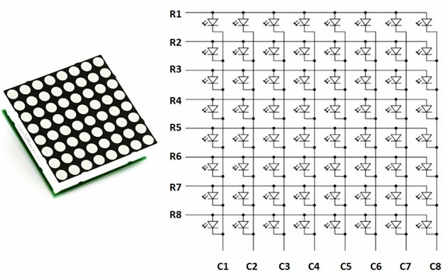
From the above schematic, we can see that the anodes of all LEDs are connected with rows and the cathodes of all LEDs are connected with columns.
LED Matrix – Schematic Diagram
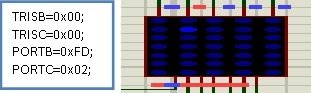
An example of a DOT matrix LED display is shown below. The Proteus simulation shows the connectivity of the LED dot matrix. The rows require a ground connection, and the columns require 3.3 V to glow a particular LED at any position. To glow the LED connected to the 1st row and 1st column, we will connect the circuit as follows:

To glow the LED connected to the 2nd row and 2nd column:
Changing 5×7 LED Matrix Interfacing in Proteus
In Proteus, by default, the LED matrix model has cathodes connected to the rows and anodes connected to the columns. We can change that and swap the configuration so that the LED’s anode connects with rows and the LED’s cathode connects with columns. A simple solution is listed below:
- Right-click on the matrix object and open “Edit Properties”.
- Click “Edit all properties as text”.
- Replace {INVERT=A,B,C,D,E,F,G} with {INVERT=1,2,3,4,5}.
Now the model will have LED matrix anodes connected to the rows and LED matrix cathodes connected to the columns.

Pic Microcontroller Displaying Characters on LED Matrix
In this section, we will discuss how to interface with an LED matrix to display characters. Firstly, we need to connect the row and the column of LED DOT MATRIX to the microcontroller’s PORT B and PORT D, respectively. Then, for printing any character, we will program the microcontroller to send data to a specific row and column at any given time. Let’s look at an example of how we can print the character “I” in the LED DOT Matrix. The code is as follows:
void main() {

  TRISB = 0x00;

  TRISD = 0x00;

  PORTB = 0x41;

  PORTD = 0xFE;

  delay_ms(200);

  PORTB = 0x41;

  PORTD = 0xFD;

  delay_ms(200);

  PORTB = 0x7F;

  PORTD = 0xFB;

  delay_ms(200);

  PORTB = 0x41;

  PORTD = 0xF7;

  delay_ms(200);

  PORTB = 0x41;

  PORTD = 0xEF;

  delay_ms(200);

  while (1) {

    PORTB = 0x41;

    PORTD = 0xFE;

    delay_ms(15);

    PORTB = 0x41;

    PORTD = 0xFD;

    delay_ms(15);

    PORTB = 0x7F;

    PORTD = 0xFB;

    delay_ms(15);

    PORTB = 0x41;

    PORTD = 0xF7;

    delay_ms(15);

    PORTB = 0x41;

    PORTD = 0xEF;

    delay_ms(15);

  }

}
In this code, we have assigned rows to PORT B and columns to PORT D. Now we send data to the first column using PORT D, and at the same time we will send data to the rows using PORT B. This will light specific LEDs, and then after a delay of a few milliseconds (15 ms), we will shift to the next column and again send data to rows. We will continue this pattern until the last column and then repeat it again and again using a while loop. Our speed is greater than 20 frames per second, so a normal eye is unable to detect the LEDs turning on and off, and hence our eyes see the letter I printed on the LED DOT Matrix. We have attached a picture below of how this code actually works:

Moving Character with LED Matrix
The trick we used for stable characters was to build one character on the display by sending data to both columns and rows very fast and then putting it in repetition with a delay of a few milliseconds. Now if we repeat the same data for each column and row for 20 frames and then scroll the column one position to the left, This will give us the effect of text moving across the DOT Matrix Display. So for LED matrix interfacing, we have to build one frame and repeat it 20 times, and after that, send data for the next frame. This shows that the character is scrolling from left to right on the display. If we are using five columns at a time, we will have to shift all five columns to the next position for this pattern to work.
Glowing Column of LED matrix
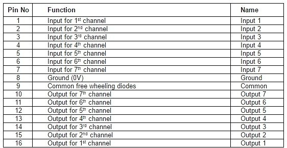
For displaying a full column (C1 or any other), column C1 should be able to sink the high current from 8 LEDs. A PIC16f877a microcontroller’s I/O pin cannot sink this much current, so external transistor arrays are required. For this purpose, we can use the ULN 2003A IC, which has seven built-in Darlington transistor arrays. The inputs of ULN2003A are active high. This means the input pins of this IC must be supplied with high logic in order to bring the corresponding output pins to ground. It can provide 50 volts and 500 mA of current in a single channel. The Input to the column of LED dots is then given by this ULN 2003A IC.
LED Matrix Interfacing with PIC Microcontroller
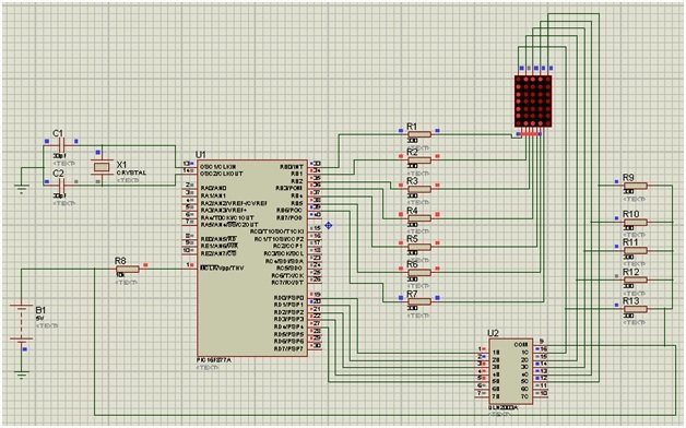
In this section, we will discuss how to connect the ULN2003A IC with a PIC Microcontroller to drive an LED Dot matrix display. Firstly, PORT B and PORT D of the PIC16F877A are used as output ports. Then PORT B is connected to the rows, and PORT D is connected to the inputs of the ULN2003A. For displaying a character, we have to give sequences of data to the row and corresponding columns. This will switch between columns, and previous LED dots will turn off while other dots turn on. In this case, we will not be able to see a particular alphabet. So to avoid it, we start a while loop with a 1 ms delay. The switching between columns is fast enough to deceive the human eye, and all we see is a steady character on the display. The connections are provided in the tables below:
| MCU Pins | Connections |
|---|---|
| RB0 – RB6 | Dot Matrix LED (R1 – R7) |
| RD0 – RD4 | ULN2003A (Pin 1 – Pin 5) |
| ULN2003A Pins | Dot Matrix Columns |
|---|---|
| Pin 16 – Pin 12 | C1 – C5 |
We have also attached a schematic showing these connections below:
LED Matrix Interfacing Example 1
In this example, we have two arrays, and we will run them continuously with a delay of 1 ms to drive the LED Dot Matrix Display. The code is provided below:
int b[5] = {
  65, 62, 62, 62, 93
};

int ch[10] = {
  254, 253, 251, 247, 239
};

void main() {

    int i;
    TRISB = 0;
    TRISD = 0;

    while (1)
    {
      for (i = 0; i < 5; i++)
      {
        PORTB = b[i];
        PORTD = ch[i];
        delay_ms(1);
      }
    }
}
We can also use the HEX codes of the arrangements to drive the LED matrix, as given in the previous example. Example: for displaying “A”, the code should be {0x7e, 0x09, 0x09, 0x09, 0x7e}, and for “B”, it is {0x7f, 0x49, 0x49, 0x49, 0x36}.
LED Matrix Interfacing Example 2
In this example, we will take the specific x and y coordinates of an LED and light it up using its coordinates. The code is provided below:
#define ROWPORT PORTB
#define ROWTRIS TRISB
#define COLPORT PORTD
#define COLTRIS TRISD

void lightLED(short row, short column); //Prototype

void main() {
  ANSELA = 0;
  ANSELB = 0;
  ANSELC = 0;
  ANSELD = 0;
  ANSELE = 0;
  /*Include this line at the top of main,
  this is to turn off the ADC Module.
  It will be explained in detail in the next Lab.
  */

  ROWTRIS = 0;
  COLTRIS = 0;
  ROWPORT = 0xFF;
  COLPORT = 0;

  lightLED(1, 2);
  while (1);
}

void lightLED(short row, short column) {
  ROWPORT = ~(1 << row);
  COLPORT = 1 << column;
}
LED Matrix Interfacing Example 3
Here we have an example of driving the diagonal LEDs of the matrix at the same time. The sample LED matrix will result in a similar pattern as shown in the figure below.
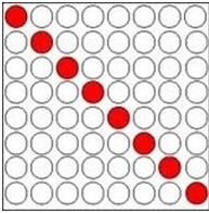
We have also attached the code below.
#define ROWPORT PORTB
#define ROWTRIS TRISB
#define COLPORT PORTD
#define COLTRIS TRISD

void lightLED(short row, short column); //Prototype

void main() {
  short i = 0;
  ANSELA = 0;
  ANSELB = 0;
  ANSELC = 0;
  ANSELD = 0;
  ANSELE = 0;
  /*Include this line at the top of main,
  this is to turn off the ADC Module.
  It will be explained in detail in the next Lab.
  */

  ROWTRIS = 0;
  COLTRIS = 0;
  ROWPORT = 0xFF;
  COLPORT = 0;

  while (1) {
    for (i = 0; i < 8; i++) {
      lightLED(1, 2);
      delay_ms(1);
    }
  }
}

void lightLED(short row, short column) {
  ROWPORT = ~(1 << row);
  COLPORT = 1 << column;
}
LED Matrix Interfacing Example 4
In this section, we will display the letter ‘A’ on the LED matrix. You can adjust this code according to your requirements by changing the 8×8 matrix array. The code is as follows:
#define ROWTRIS TRISB
#define COLPORT PORTD
#define COLTRIS TRISD

void lightLED(short row, short column); //Prototype

const short H[8][8] = {
{0,1,1,1,1,1,1,1},
{1,0,0,0,0,0,0,1},
{1,0,0,0,0,0,0,1},
{1,0,0,0,0,0,0,1},
{1,1,1,1,1,1,1,1},
{1,0,0,0,0,0,0,1},
{1,0,0,0,0,0,0,1},
{1,0,0,0,0,0,0,1}
};
void main() {
  short i = 0, j = 0;
  ANSELA = 0;
  ANSELB = 0;
  ANSELC = 0;
  ANSELD = 0;
  ANSELE = 0;
  /*Include this line at the top of main,
  this is to turn off the ADC Module.
  It will be explained in detail in the next Lab.
  */

  ROWTRIS = 0;
  COLTRIS = 0;
  ROWPORT = 0xFF;
  COLPORT = 0;

  while (1) {
    for (i = 0; i < 8; i++) {
      for (j = 0; j < 8; j++) {
        if (H[i][j]) {
          lightLED(i, j);
          delay_us(500);
        }
      }
    }
  }
}

void lightLED(short row, short column) {
  ROWPORT = ~(1 << row);
  COLPORT = 1 << column;
}
Video Demonstration
Conclusion
In this article, we have discussed the following topics:
- LED Matrix and its schematic.
- Proteus Interfacing of the LED Matrix.
- Displaying and moving characters using an LED matrix
- LED Matrix interface with a PIC microcontroller.
- 4 Examples.
Related Articles
You may also like to read:
- MAX7219 8-Digit LED Display Driver.
- 8×8 LED Matrix Interfacing with MAX7219 and Pic Microcontroller.
- 1388A – 8×8 LED Matrix Module.
- What is Led matrix? Types of Dot matrix display with working.
- MAX7219 LED Dot Matrix Display Interfacing with Arduino.
If you face any issues while following this tutorial, feel free to comment below.
its great , i appreciate Engr. Khadija Yasmin, How do you call the device connected to the last port on pic 16 micro controller?
wow galeng
Thanks you Malik
why have nt you defined XTAL_FREq for ms_delay ?
LED matrix interfacing interfacing to display characters
what was the compiler used for this program?
Good one. And I loved it.. But please how do I scroll it?
LED moving message display using pic16f877a circuit diagram in protius ans simulation , source code of it please sent to my email. my email is vgmuppidwar@gmail.com