In this tutorial, we will see how to use ESP32 Hall effect sensor with Arduino IDE. The ESP32 is a powerful microcontroller that supports various types of sensors and peripherals. Some ESP32 boards, such as the ESP32 DevKitC, include a Hall effect sensor as part of their SoC. The Hall effect sensor on the ESP32 can measure changes in magnetic fields and provide digital readings based on the detected magnetic field strength.
If you are a beginner and do not have an idea about the ESP32 development board, you can check this guide:
Arduino IDE is used to program ESP32 in these series of tutorials and we can install an ESP32 board in Arduino IDE. You can check this tutorial:

How Hall Effect Sensors Work?
Hall effect sensors detect changes in the presence or strength of a magnetic field. They detect the magnetic field of lines in their surroundings and produce a voltage at the output pins of the sensor.
The Hall effect sensor works on the principle of the Hall effect, which states that when a current-carrying conductor is exposed to a perpendicular magnetic field, a voltage difference is induced across the conductor. The magnitude of this voltage difference is directly proportional to the strength of the magnetic field.
Applications
The Hall effect sensor on the ESP32 can be used for a variety of applications, such as proximity sensing, detecting the presence of magnets, measuring rotational speed, and even building simple compasses. By leveraging the capabilities of the ESP32 microcontroller, developers can easily interface with the Hall effect sensor and incorporate magnetic field detection into their projects.
- Alternating current measurement using a hall effect sensor.
- Hall effect sensor interfacing with Arduino
- Magnetic field strength measurement using a pic microcontroller
- ACS712 current sensor interfacing with Arduino
- Magnetic field detection using a pic microcontroller
How to use the Hall Effect Sensor of ESP32?
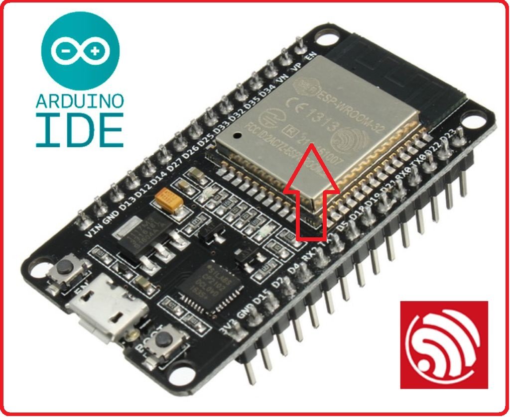
Now, let’s move to the main topic of this tutorial. The first question is where the hall effect sensor is located in the ESP32 chip. All ESP32 chips, it is located under this metal cover of the ESP32 board. When you bring a magnet near to this metal cover, it detects the variations in the magnetic field and produces an output voltage according to the strength of the magnetic field.
ESP32 development board does not provide any pin for the output measurement of the hall sensor. Because we only want to read the value of voltage according to magnetic field strength in the surroundings of the ESP32 board. Therefore, the output of the built-in hall effect sensor saves in a register of the ESP32 board, and we can easily read it with Arduino IDE’s built-in function.
ESP32 Hall Sensor Read API
The ESP32 provides access to the Hall effect sensor through the hall_sensor API. You can use the hallRead() function from the esp32-hal-hall.h library to read the Hall effect sensor value. Here’s an example of how you can use hallRead() in Arduino IDE:
int hallValue = hallRead();ESP32 Hall Effect Sensor Code
It is straightforward to measure the output of the Hall effect sensor using this simple code and the HallRead() function of the Arduino IDE. The HallRead() role reads the value of the output of the hall sensor and returns the result in a declared variable as we stated in the code below.
int hall_sensor_value = 0;
void setup()

{
Serial.begin(9600);  // It defines the baud rate of 9600 bits per second to serial monitor
}
void loop()

{
hall_sensor_value = hallRead();
Serial.print("Hall sensor value = ");
Serial.println(hall_sensor_value);
delay(500);
}
The code given above is very simple, and all code is the same as used in the last tutorial except the hallRead() function. This function does not need any argument. It reads the value of hall sensor output which is stored in a register of ESP32. We can simply save the output of hallRead() function in any variables. In this code, we have saved the output voltage of the hall sensor in a variable name” hall_sensor_value. After that, we are sending these values to the serial monitor. The output of hallRead() function can be either positive or negative depending on the direction magnetic field.
Now just copy the above code and paste it into Arduino IDE. After compiling the code, upload the code to Arduino IDE by clicking on the Arduino button.
Make sure you have selected the correct COM pin to which the ESP32 board is connected. After uploading the code, open the serial monitor of Arduino IDE by going to the tools menu.
You will get output like this on the serial monitor.

As you can see in the above picture, we are getting values according to the strength of the magnetic field, and also negative values show the direction of the field.
ESP32 Read Hall Effect Sensor Value with MicroPython
To read the Hall effect sensor value on the ESP32 using MicroPython. Here’s an example of how you can read the Hall effect sensor value in MicroPython:
import esp32

while True:
    hall_value = esp32.hall_sensor()
    print(hall_value)
In this code, we import the esp32 module, which provides access to various ESP32-specific functionalities, including the built-in Hall effect sensor.
Inside the while loop, we call the esp32.hall_sensor() function to read the Hall effect sensor value. The function returns an integer representing the magnetic field strength or polarity.
Finally, we print the hall_value to the console or serial output. The loop continues indefinitely, continuously reading and printing the sensor value.
Make sure you have MicroPython installed on your ESP32 and are running this code within a MicroPython environment that supports the ESP32’s built-in Hall effect sensor.
You may also like to check related tutorials on ESP32:
- ESP32 Capacitive Touch Sensor – How to use them as a button
- ESP32 Web Server in Arduino IDE: Control LEDs
- ESP32 PWM with Arduino IDE ( LED Fading Example )
- I2C LCD interfacing with ESP32 and ESP8266 in Arduino IDE
- ESP32 Password-protected web server in Arduino IDE
- How to Assign Static IP address to ESP32 in Arduino IDE