In this tutorial, we will learn to create a simple web server with ESP32 using Arduino IDE framework. It will host HTML and CSS files and serve them to clients whenever it receives an HTTP GET request from any web client ( web browser). We can use this ESP32 web server to control GPIO pins or LEDs. To access the web server, ESP32 should be connected to the same WiFi network to which your mobile or computer is connected and your web client application will run on the same device.
We have a similar project with ESP32 and ESP8266 using MicroPython and Arduino IDE:
Setting up Arduino IDE:
We will be using Arduino IDE to program our ESP32 development board. Before we move ahead, make sure you have the latest version of Arduino installed on your computer. Moreover, you should also have an ESP32 add-on in Arduino IDE. You can check this tutorial:
Recommended Components
The following components are used in this project or are helpful for building it with the ESP32.
| Component | How it’s used in this project | Buy on Amazon |
|---|---|---|
| ESP32 Development Board (DevKit V1) | The main microcontroller board that runs the project code and controls all connected parts. | Check Price |
| Micro USB Cable | Connects the ESP32 to your computer to upload code and provide power. | Check Price |
| Breadboard | Lets you build the circuit and connect components without soldering. | Check Price |
| Jumper Wires | Used to wire the ESP32 to the other components on the breadboard. | Check Price |
| 5mm LED | The output LED that is switched on and off from the ESP32 web server. | Check Price |
| Resistor Kit (220 Ω / 4.7k) | A 220 Ω resistor limits current to protect the LED. | Check Price |
As an Amazon Associate we earn from qualifying purchases. Prices and availability are accurate as of the date/time indicated and are subject to change.
ESP32 Web Server Project Overview
You will learn the following in this ESP32 web server tutorial:
- Learn to make a web server using ESP32 and Arduino IDE
- How to make a web server control LEDs from a local network using an ESP32
- What is a web server? How to use ESP32 as a Web server
- How an ESP32 web server can serve HTML, CSS, and Javascript files to web clients by acting as a server.
Introducing Web server?
When we talk about web servers in the context of the Internet of Things, the web server is nothing but the location where our website files are stored, and the Web server processes these files to clients based on the request of a client. Website files are web pages of any site. Like you are using this website to read an article on how to make an EPS32 web server, this webpage is stored in a server of our hosting company. Hence, when you click on the link to open this article, you make a request as a client to a server of our hosting company.
After receiving this particular page request, our hosting company server processes this request to display this webpage. Similarly, we can use ESP32 as a host to store web pages, and when someone requests a web page through a local network, esp32 will serve this webpage. The picture below provides a view of client-server-based communication.

Web Server and Client Communication
This is a basic idea of server and client-based communication over the Internet. Now the question is how can we establish communication between the client and the Web server? HTTP which is also known as hypertext transfer control is a protocol that is used to transfer data between the web client and Web server. The web server in this tutorial will be ESP32 and the web client will be any web browser or Android application. Whenever a web client needs to access any web files, it starts an HTTP GET request to the web server.
How Does a Web Server Respond to a Client Request?
After receiving an HTTP GET request, the server responds with web pages, and the web browser knows how to use that response to display a web page. The web server also communicates through the HTTP protocol. If web files are unavailable on the server or if it is down due to technical reasons, you will see an error message, specifically error 404, on the web browser. In the figure above, there is only one client and one server depicted. However, a server can connect to multiple web clients and service their requests through the HTTP protocol. The web server is also referred to as the server host, as it listens to other web clients and services their requests.
You can find more information about HTTP GET and POST requests in the following articles:
ESP32 Web Server in Different Modes
The ESP32 microcontroller can act as a web server in both station and Access Point modes, allowing it to serve web pages and handle HTTP requests. This WiFi module has very important features to be used in a soft access point mode, station mode, and both modes at the same time.
In this tutorial, we will see how to create an ESP32 web server in station mode only. If you want to know how to create Soft Access Point Web Server with ESP32, you can read the following article:
Here’s how the ESP32 Web Server can be implemented in various modes
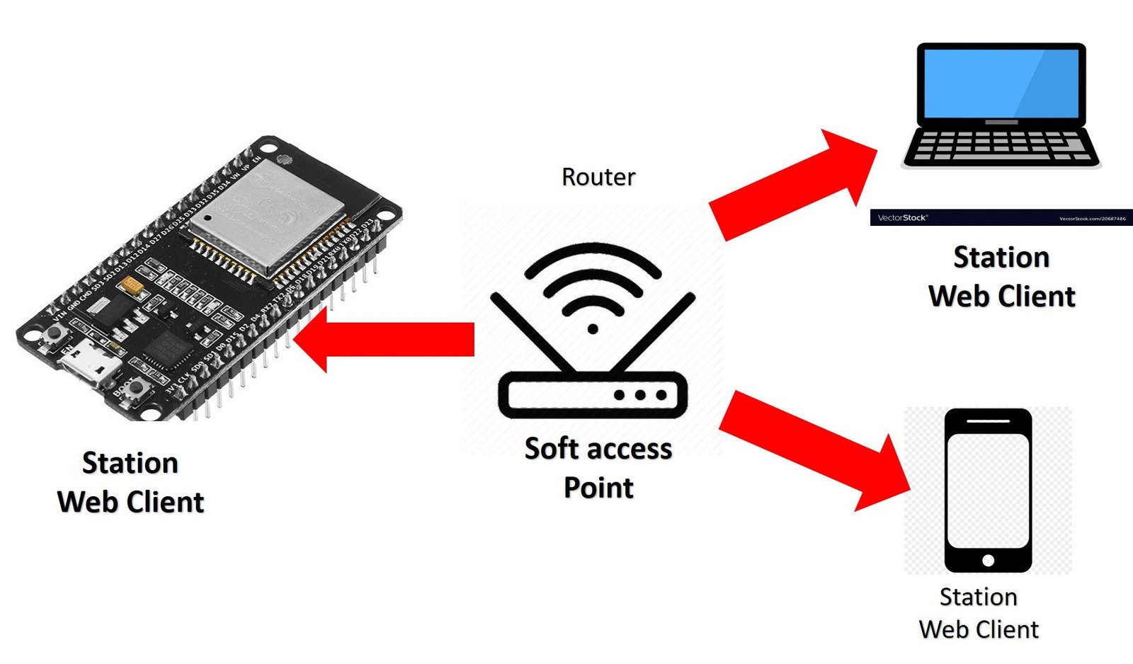
Station Mode or STA
In this mode, ESP32 board connects to your WiFi network through a router. So the medium of communication between the web client and ESP32 is the router. It gets the IP address from the Wifi router. With this IP address, web clients can access the Web server through an existing local network.
It can act as a web server, serving web pages to clients connected to the same network. Clients can access the web pages hosted by the ESP32 by entering its IP address in a web browser.
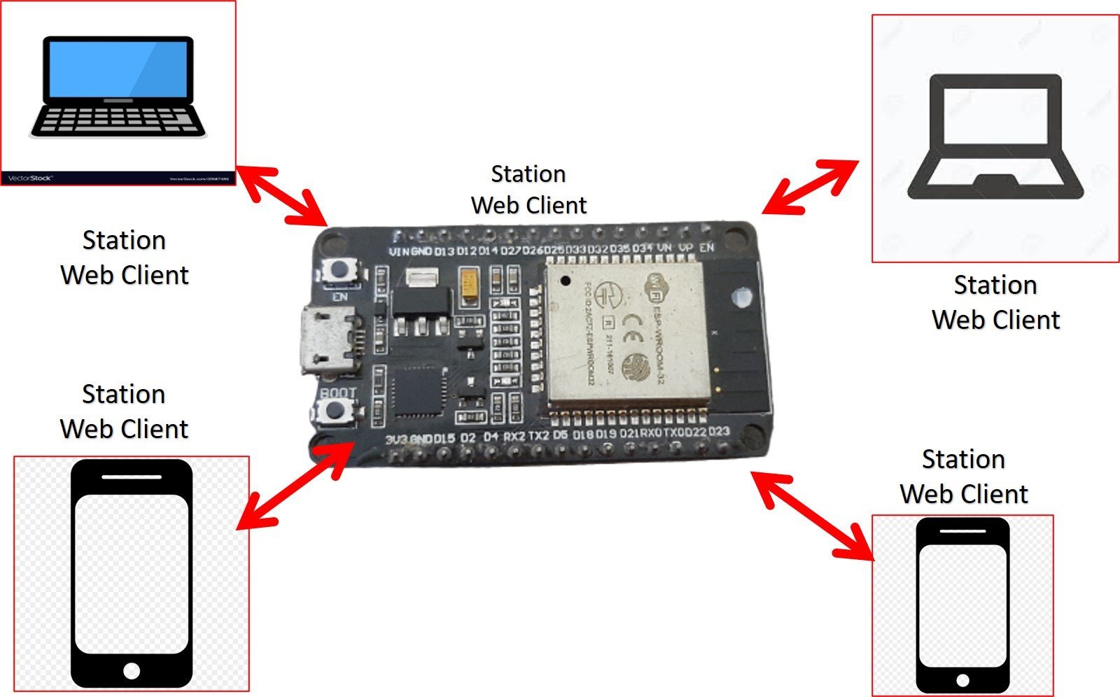
Soft Access Point Mode
In this mode, ESP32 is used to create its own wireless WiFi network similar to your existing WiFi router. In this mode, we do not need to connect ESP2 to the WiFi network. Up to 5 devices can connect to this Wifi network created by this WiFi board.
The ESP32 can function as a web server, serving web pages to the connected clients. Clients can access the web server by connecting to the ESP32’s Wi-Fi network and entering its IP address in a web browser.
You can learn more about access point web servers here:
- MicroPython: ESP32/ESP8266 Access Point – Web Server Example
- ESP32 Soft Access Point Web Server in Arduino IDE
How to use ESP32 as a Web Server in station mode
In this mode, the ESP32 connects to an existing Wi-Fi network as a client. It can then act as a web server, serving web pages to clients connected to the same network. Clients can access the web pages hosted by the ESP32 by entering its IP address in a web browser.

Getting ESP32 Web Server IP Address
We can have multiple clients and a single host server, such as the ESP32 or any IoT development board. Now, the question is how a web client can access the web server hosted on the ESP32. When a device connects to a network, it is assigned an IP address. We can use this assigned IP address to refer to the device. For instance, when we connect the ESP32 to the Wi-Fi network, it will be assigned an IP address. We can use this IP address to access the ESP32 server through a web browser.

How to Access the Web Page?
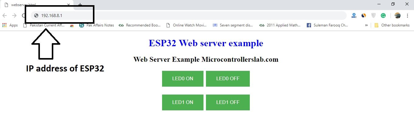
To access web pages hosted on ESP32, we need to get its IP address which is assigned to it when it connects to the internet. In the programming part, we will show you how to get its IP address.
After getting the IP address, simply place it in a web browser, and you will get the response from the ESP32 web server. For example, the web files which we stored in ESP32 are like the one shown below. It will show this web file in your web browser.
Until now, we have learned about web servers and how ESP32 can be used as a web server.
ESP32 Web Server to Control GPIOs and Relays
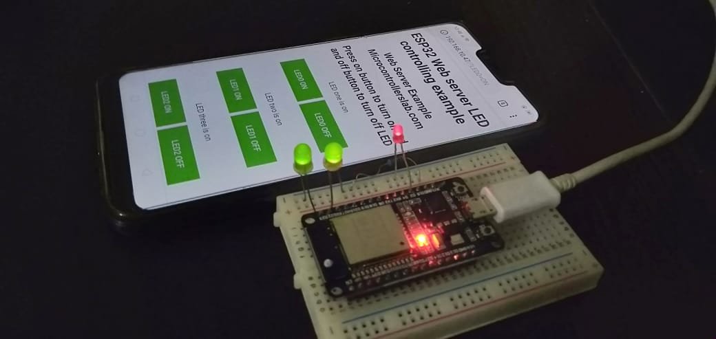
Now let’s explore how to control three light-emitting diodes (LEDs) using a web server. We can access this server through any web browser installed on a personal computer, laptop, mobile device, or tablet. In this tutorial, we will control three LEDs using a web browser. For the demonstration, we will be using three light-emitting diodes. You can refer to the schematic below and replicate the connections on a breadboard.
The connection diagram indicates the general-purpose input-output (GPIO) pins we have used, but feel free to use any GPIO pin that suits your needs. It’s important to note that this tutorial serves as a demonstration only. In an actual project, you would use relays to control AC devices, such as a home automation project. We will also publish a blog article in the near future that delves into home automation projects.
Schematic Diagram

Components list
To make this schematic, you will need the following components :
- Breadboard
- ESP32 board ( we are using ESP32 devkit DOIT 30 pin version)
- three 100-ohm resistors
- Jumper wires
- 3 LEDs
In the schematic, we are using GPIO pins 15, 22, and 23 as digital output pins. These pins are connected with light-emitting diodes through current limiting resistors. For more information about how to interface LED with this board, you can check LED blinking with ESP32 article. LED1 is connected with GPIO pin 23. LED2 is connected with GPIO pin 22 and LED3 is connected with GPIO pin fifteen.
Before reading this tutorial further, I suggest you read the following prerequisites :
ESP32 Web Server Code
Now, let’s move to the main part of the ESP32 web server tutorial. Remember in this tutorial we are using ESP32 module in station mode.
This Arduino code let user control three LEDs with separate on and off buttons from a web page.
#include <WiFi.h>

const char* WIFI_NAME= "Enter your WiFi name here";
const char* WIFI_PASSWORD = "Enter password of WiFi here";

WiFiServer server(80);

String header;

String LED_ONE_STATE = "off";
String LED_TWO_STATE = "off";
String LED_THREE_STATE = "off";


const int GPIO_PIN_NUMBER_22 = 22;
const int GPIO_PIN_NUMBER_23 = 23;
const int GPIO_PIN_NUMBER_15 = 15;


void setup() {
Serial.begin(115200);
pinMode(GPIO_PIN_NUMBER_22, OUTPUT);
pinMode(GPIO_PIN_NUMBER_23, OUTPUT);
pinMode(GPIO_PIN_NUMBER_15, OUTPUT);

digitalWrite(GPIO_PIN_NUMBER_22, LOW);
digitalWrite(GPIO_PIN_NUMBER_23, LOW);
digitalWrite(GPIO_PIN_NUMBER_15, LOW);


Serial.print("Connecting to ");
Serial.println(WIFI_NAME);
WiFi.begin(WIFI_NAME, WIFI_PASSWORD);
while (WiFi.status() != WL_CONNECTED) {
delay(1000);
Serial.print("Trying to connect to Wifi Network");
}
Serial.println("");
Serial.println("Successfully connected to WiFi network");
Serial.println("IP address: ");
Serial.println(WiFi.localIP());
server.begin();
}

void loop(){
WiFiClient client = server.available();
if (client) {
Serial.println("New Client is requesting web page");
String current_data_line = "";
while (client.connected()) {
if (client.available()) {
char new_byte = client.read();
Serial.write(new_byte);
header += new_byte;
if (new_byte == '\n') {

if (current_data_line.length() == 0)
{

client.println("HTTP/1.1 200 OK");
client.println("Content-type:text/html");
client.println("Connection: close");
client.println();

if (header.indexOf("LED0=ON") != -1)
{
Serial.println("GPIO23 LED is ON");
LED_ONE_STATE = "on";
digitalWrite(GPIO_PIN_NUMBER_22, HIGH);
}
if (header.indexOf("LED0=OFF") != -1)
{
Serial.println("GPIO23 LED is OFF");
LED_ONE_STATE = "off";
digitalWrite(GPIO_PIN_NUMBER_22, LOW);
}
if (header.indexOf("LED1=ON") != -1)
{
Serial.println("GPIO23 LED is ON");
LED_TWO_STATE = "on";
digitalWrite(GPIO_PIN_NUMBER_23, HIGH);
}
if (header.indexOf("LED1=OFF") != -1)
{
Serial.println("GPIO23 LED is OFF");
LED_TWO_STATE = "off";
digitalWrite(GPIO_PIN_NUMBER_23, LOW);
}
if (header.indexOf("LED2=ON") != -1)
{
Serial.println("GPIO15 LED is ON");
LED_THREE_STATE = "on";
digitalWrite(GPIO_PIN_NUMBER_15, HIGH);
}
if(header.indexOf("LED2=OFF") != -1) {
Serial.println("GPIO15 LED is OFF");
LED_THREE_STATE = "off";
digitalWrite(GPIO_PIN_NUMBER_15, LOW);
}

client.println("<!DOCTYPE html><html>");
client.println("<head><meta name=\"viewport\" content=\"width=device-width, initial-scale=1\">");
client.println("<link rel=\"icon\" href=\"data:,\">");
client.println("<style>html { font-family: Helvetica; display: inline-block; margin: 0px auto; text-align: center;}");
client.println(".button { background-color: #4CAF50; border: 2px solid #4CAF50;; color: white; padding: 15px 32px; text-align: center; text-decoration: none; display: inline-block; font-size: 16px; margin: 4px 2px; cursor: pointer; }");
client.println("text-decoration: none; font-size: 30px; margin: 2px; cursor: pointer;}");
// Web Page Heading
client.println("</style></head>");
client.println("<body><center><h1>ESP32 Web server LED controlling example</h1></center>");
client.println("<center><h2>Web Server Example Microcontrollerslab.com</h2></center>" );
client.println("<center><h2>Press on button to turn on led and off button to turn off LED</h3></center>");
client.println("<form><center>");
client.println("<p> LED one is " + LED_ONE_STATE + "</p>");
// If the PIN_NUMBER_22State is off, it displays the ON button
client.println("<center> <button class=\"button\" name=\"LED0\" value=\"ON\" type=\"submit\">LED0 ON</button>") ;
client.println("<button class=\"button\" name=\"LED0\" value=\"OFF\" type=\"submit\">LED0 OFF</button><br><br>");
client.println("<p>LED two is " + LED_TWO_STATE + "</p>");
client.println("<button class=\"button\" name=\"LED1\" value=\"ON\" type=\"submit\">LED1 ON</button>");
client.println("<button class=\"button\" name=\"LED1\" value=\"OFF\" type=\"submit\">LED1 OFF</button> <br><br>");
client.println("<p>LED three is " + LED_THREE_STATE + "</p>");
client.println ("<button class=\"button\" name=\"LED2\" value=\"ON\" type=\"submit\">LED2 ON</button>");
client.println ("<button class=\"button\" name=\"LED2\" value=\"OFF\" type=\"submit\">LED2 OFF</button></center>");
client.println("</center></form></body></html>");
client.println();
break;
}
else
{
current_data_line = "";
}
}
else if (new_byte != '\r')
{
current_data_line += new_byte;
}
}
}
// Clear the header variable
header = "";
// Close the connection
client.stop();
Serial.println("Client disconnected.");
Serial.println("");
}
}Uploading Code to ESP32
Follow these steps to upload the code, after copying this code to Arduino IDE.
- First of all, you need to add the name of your WiFi network and password to the following two lines:
const char* WIFI_NAME= "Enter your WiFi name here";
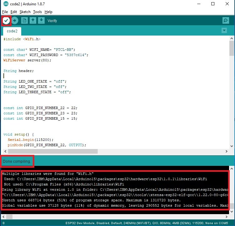
const char* WIFI_PASSWORD = "Enter password of WiFi here";You don’t need to make any other changes in the code. Now first compile this code by clicking on the verify button on the Arduino IDE. ESP32 codes usually take more time to compile than other microcontrollers, so don’t worry about it and wait for a while. After it’s done with compilation, it will show the following message in the compilation window.
Now click on the upload button to upload this code into the ESP32.

Before uploading the program, make sure you should have selected the right COM port to which your board is connected.

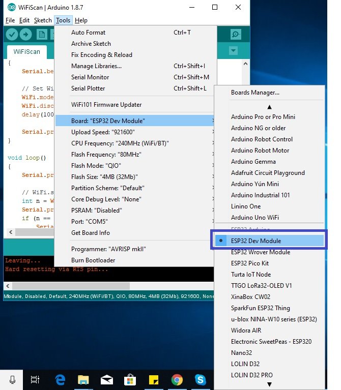
Also, you should select the ESP32 dev module from the tools and boards menu as shown below:
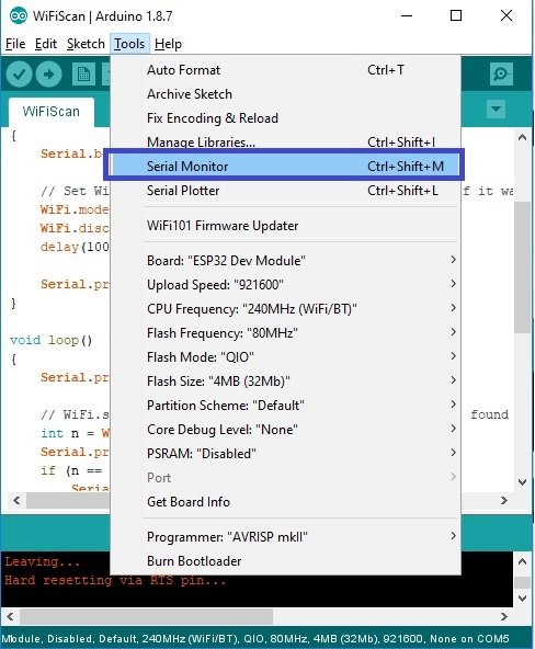
After you see the message of done uploading on Arduino IDE, open the serial monitor by clicking on the serial monitor option. Select the baud rate of 115200 in the serial monitor window.
After ESP32 Web Server code is uploaded successfully, you will see this message :

Getting IP address
Now, open the serial monitor and press the reset button on the ESP32 dev kit board. You will see a message stating “Trying to connect to a WiFi network.” After a short period of time, you will receive the message “Successfully connected to the WiFi network,” along with the displayed IP address. We will use this IP address to access web server as shown in the figure below:

Accessing ESP32 Web Server
In this section, we will see how to open the web page which is stored in ESP32. To access the web server, paste the IP address which we noted in the last step into any web browser of a device which is connected to the same network to which ESP32 is connected. You will find this web page in your browser.
How ESP32 Web Server Work?
After accessing a web page through a web browser, you can check the serial monitor where you will see the web page HTTP GET request from a client over HTTP protocol. You will see this message on the serial monitor.
New Client is requesting web page
GET / HTTP/1.1
Host: 192.168.10.47
Connection: keep-alive
Upgrade-Insecure-Requests: 1
User-Agent: Mozilla/5.0 (Windows NT 10.0; Win64; x64) AppleWebKit/537.36 (KHTML, like Gecko) Chrome/72.0.3626.121 Safari/537.36
Accept: text/html,application/xhtml+xml,application/xml;q=0.9,image/webp,image/apng,*/*;q=0.8
Accept-Encoding: gzip, deflate
Accept-Language: en-US,en;q=0.9
AlexaToolbar-ALX_NS_PH: AlexaToolbar/alx-4.0.3
This message specifies the operational parameters for the HTTP request transaction between the client and the server to serve the web page. However, there’s no need to be concerned about these details. The key concept to understand is what occurs when someone presses the on/off buttons to control the LED’s state. Now, let’s examine the behavior on the browser and the corresponding messages sent to the ESP32 board, which are displayed on the serial monitor.
Controlling LEDs from web page
When you press the LED0 button, you will notice that the IP address in the web browser will include the additional text “/?LED0=ON”. This message will be sent to the ESP32 board, and you will observe it in the string “GET /?LED0=ON HTTP/1.1” on serial monitor. The ESP32 will receive this request from the web client and proceed to turn on the LED0, as specified in the provided code. The working of the code will be explained in detail in the “How the Code Works” section. Additionally, you will see the state of the LED being displayed on the web page. Similarly, you can test the other buttons and observe the same response.

You should follow these points while testing the web server.
- First, you should press each button and check if you see the same message in the URL and also on the serial monitor of Arduino IDE.
- Also check, if the state of the LED message is changing according to the button you pressed on the web page.
- Also see, if the respective LED is toggling according to the pressed button.
How Does the ESP32 Web Server Code Work?
Now we will see how this code work and I will provide you details of function and each line of the code.
WiFi.h is a Wi-Fi library. We will include this library because we will be using the WiFi function to connect ESP32 to a network, to send data to the client, and to receive data from the client. This library is pre-installed in Arduino IDE. So, we will just include it with the #include directive.
#include <WiFi.h>Connect to WiFi
These two variables are used to store the name and password of the Network to which you want to connect your ESP32 board. You should replace “ PTCL-BBB” with your wireless feudality network name and also put the password in the WIFI_password variable.
const char* WIFI_NAME= "PTCL-BB";
const char* WIFI_PASSWORD = "5387c614";
Whenever we set the Web server, when need to define its ports name, this line will set the WiFiServer() at port 80.
WiFiServer server(80);This string variable name is used to store all the data received by ESP32 development board through HTTP requests.
String header;Define LEDs
As I mentioned, we are toggling three LEDs in this tutorial, so these three variables are used to store the state of these three lights emitting diodes. Initially, we set the state of LEDs to off state. But these states will change according to the status of LEDs.
String LED_ONE_STATE = "off";
String LED_TWO_STATE = "off";
String LED_THREE_STATE = "off";
GPIO pins 22, 23 and 15 are used with LEDs. So, these three statements will give the name to these GPIO pins. Whenever we want to refer to these pins in our code, we will use them by these name instead of the pin number.
const int GPIO_PIN_NUMBER_22 = 22;
const int GPIO_PIN_NUMBER_23 = 23;
const int GPIO_PIN_NUMBER_15 = 15;
In setup() function first, we initialized the baud rate of ‘serial.begin’ function at the rate of 115200 bits per second.
Serial.begin(115200);Now we define these GPIO pins as digital output using pinMode() function and also set these general purpose input output pins to digitally low using digitalWrite() function.
  pinMode(GPIO_PIN_NUMBER_22, OUTPUT);
  pinMode(GPIO_PIN_NUMBER_23, OUTPUT);
  pinMode(GPIO_PIN_NUMBER_15, OUTPUT);
  digitalWrite(GPIO_PIN_NUMBER_22, LOW);
  digitalWrite(GPIO_PIN_NUMBER_23, LOW);
  digitalWrite(GPIO_PIN_NUMBER_15, LOW);
Now, We will discuss some of the functions from WiFi library which are used in this course. So that you can understand code more clearly.
Connecting to WiFi
First, it will print a message “connecting to ” along with WiFi name. After that, it will connect to a network. If it is successfully connected to a wifi network. you will see an IP address and successfully to connect to a Wifi network message on Serial monitor. While it is trying to connect to the internet, it will show ” trying to connect to wifi network. Server.begin () function start the server and now any web client can access the web page with this IP address.
Serial.print("Connecting to ");
Serial.println(WIFI_NAME);
WiFi.begin(WIFI_NAME, WIFI_PASSWORD);
while (WiFi.status() != WL_CONNECTED)

 {
delay(1000);
Serial.print("Trying to connect to Wifi Network");
}
Serial.println("");
Serial.println("Successfully connected to WiFi network");
Serial.println("IP address: ");
Serial.println(WiFi.localIP());
server.begin();
The main loop service the web page to the client and also receive data through HTTP get request about the status of GPIO pins. Inside the loop function, this line is used to receive a request from new web clients. If the client request is available, server.avaialble () function stores logical one value in variable client.
WiFiClient client = server.available();Now if the client request is available, These statements will start receiving data from the client and stores the data in header string and it will continue receiving data until ‘\n’ is not found which means client has disconnected.
if (client)

{
Serial.println("New Client is requesting web page");
String current_data_line = "";
while (client.connected()) {
if (client.available()) {
char new_byte = client.read();
Serial.write(new_byte);
header += new_byte;
if (new_byte == '\n') {

if (current_data_line.length() == 0)
{

client.println("HTTP/1.1 200 OK");
client.println("Content-type:text/html");
client.println("Connection: close");
client.println();
Controlling LEDs Code
Now based on the received data from the client which we stored in a string ‘header’, we will toggle the respective LED on and off. These conditions will check if the button is pressed or not on. If LED0 button is pressed, as we have seen previously, we will get a message of ‘?LED0=0N” from client and we will save this message in header string. These lines use header.indexof () function which checks if a specific string is available in the header or not, if available, it will turn on and turn off the respective digital pin and also change the status of the LED which will be updated on the Web server. We have three buttons and each button has two states. Therefore here we have six if conditions to check what is received in header string.
if (header.indexOf("LED0=ON") != -1)
{
Serial.println("GPIO23 LED is ON");
LED_ONE_STATE = "on";
digitalWrite(GPIO_PIN_NUMBER_22, HIGH);
}
if (header.indexOf("LED0=OFF") != -1)
{
Serial.println("GPIO23 LED is OFF");
LED_ONE_STATE = "off";
digitalWrite(GPIO_PIN_NUMBER_22, LOW);
}
if (header.indexOf("LED1=ON") != -1)
{
Serial.println("GPIO23 LED is ON");
LED_TWO_STATE = "on";
digitalWrite(GPIO_PIN_NUMBER_23, HIGH);
}
if (header.indexOf("LED1=OFF") != -1)
{
Serial.println("GPIO23 LED is OFF");
LED_TWO_STATE = "off";
digitalWrite(GPIO_PIN_NUMBER_23, LOW);
}
if (header.indexOf("LED2=ON") != -1)
{
Serial.println("GPIO15 LED is ON");
LED_THREE_STATE = "on";
digitalWrite(GPIO_PIN_NUMBER_15, HIGH);
}
if(header.indexOf("LED2=OFF") != -1) {
Serial.println("GPIO15 LED is OFF");
LED_THREE_STATE = "off";
digitalWrite(GPIO_PIN_NUMBER_15, LOW);
}
Displaying HTML on web server
The next part of the program is to display HTML and CSS code to the web browser. This client.println () function is used to send HTML and CSS commands to the client who is accessing a web server through an IP address. This HTML file we want to send to a client. You can find further details of HTML and CSS on this link.
<!DOCTYPE html>
<html>
<head>
<style>
.button {
background-color: #4CAF50;
border: 2px solid #4CAF50;;
color: white;
padding: 15px 32px;
text-align: center;
text-decoration: none;
display: inline-block;
font-size: 16px;
margin: 4px 2px;
cursor: pointer;
}
</style>
</head>
<body>
<center><h1 style="color:blue;">ESP32 Web server LED controlling example</h1></center>
<center><h2 style="color:black;">Web Server Example Microcontrollerslab.com</h2></center>
<center><h2 style="color:Green;">Press "ON" button to turn on led and "OFF" button to turn off LED</h3></center>
<form>
<center>
<button class="button" name="LED0" value="ON" type="submit">LED0 ON</button>
<button class="button" name="LED0" value="OFF" type="submit">LED0 OFF</button><br><br>
<button class="button" name="LED1" value="ON" type="submit">LED1 ON</button>
<button class="button" name="LED1" value="OFF" type="submit">LED1 OFF</button> <br><br>
<button class="button" name="LED2" value="ON" type="submit">LED2 ON</button>
<button class="button" name="LED2" value="OFF" type="submit">LED2 OFF</button>
</center>
</form>
</body>
</html>- We will serve this HTML and CSS file to a web client through ESP32. Whenever any web client try to access the web page through an IP address, we will send this HTML page.
- Buttons are used to control LEDs. Whenever a web client press the button, we receive a HTTP request. Based on the HTTP request, we take action and control the LEDs.
Displaying web page with ESP32
But we can send it through client.println() function only. So now let’s see how to set up web page through ESP32. This line will show that we want to send HTML file.
client.println("<!DOCTYPE html><html>");This line is used because we want to make our web page accessible on every device like a computer, laptop, mobile, and tablet and it will make the web page responsive.
client.println("<head><meta name=\"viewport\" content=\"width=device-width, initial-scale=1\">");These lines are used to give style and colors to texts and buttons used on the webpage. They make the appearance of the web page better. For in this line, we are using font-family Helvetica and set the color of a web page as default which we can change later and also set the text to the center of the page.
client.println("<style>html { font-family: Helvetica; display: inline-block; margin: 0px auto; text-align: center;}");To give style to buttons and also color, this line will set the background color of green and border-color black and text color white. It also sets padding, text alignment and font size of the text used inside the buttons.
client.println(".button { background-color: #4CAF50; border: 2px solid #4CAF50;; color: white; padding: 15px 32px; text-align: center; text-decoration: none; display: inline-block; font-size: 16px; margin: 4px 2px; cursor: pointer; }");
client.println("text-decoration: none; font-size: 30px; margin: 2px; cursor: pointer;}");
These code statements print the heading parts of the code and display a text message on server.
client.println("</style></head>");
client.println("<body><center><h1>ESP32 Web server LED controlling example</h1></center>");
client.println("<center><h2>Web Server Example Microcontrollerslab.com</h2></center>" );
client.println("<center><h2>Press on button to turn on led and off button to turn off LED</h3></center>");
client.println("<form><center>");
HTML Code to display Button and LED status
This part is used to display buttons and also the status of LEDs on a web page.
client.println("<p> LED one is " + LED_ONE_STATE + "</p>");
// If the PIN_NUMBER_22State is off, it displays the ON button
client.println("<center> <button class=\"button\" name=\"LED0\" value=\"ON\" type=\"submit\">LED0 ON</button>") ;
client.println("<button class=\"button\" name=\"LED0\" value=\"OFF\" type=\"submit\">LED0 OFF</button><br><br>");
client.println("<p>LED two is " + LED_TWO_STATE + "</p>");
client.println("<button class=\"button\" name=\"LED1\" value=\"ON\" type=\"submit\">LED1 ON</button>");
client.println("<button class=\"button\" name=\"LED1\" value=\"OFF\" type=\"submit\">LED1 OFF</button> <br><br>");
client.println("<p>LED three is " + LED_THREE_STATE + "</p>");
client.println ("<button class=\"button\" name=\"LED2\" value=\"ON\" type=\"submit\">LED2 ON</button>");
client.println ("<button class=\"button\" name=\"LED2\" value=\"OFF\" type=\"submit\">LED2 OFF</button></center>");
client.println("</center></form></body></html>");
client.println();
So this is all about this first tutorial on creating a web server using ESP32 in Arduino IDE.
Arduino WiFi Functions
Details of the functions used in this code are given below:
- WifiServer(): This procedure is used to create a server that is used to listen to incoming HTTP requests from the web client.
- WiFi.begin(ssid, password): This function is initialized the WiFi library with two arguments as an input to this function. The first argument is the name of the network and the second argument is the password of the wireless network.
- WiFi.connected(): This function check either ESP32 is connected to network or not. It will return the status as TRUE or FALSE depending on the connection.
- WiFilocalIP(): If ESP32 is successfully connected with a network, we can use this function to get the IP address which is assigned to the board.
- server.begin(): It will tell start the connection to the web client and start receiving requests from the Web clients.
If you want to make an asynchronous or WebSocket-based web server with ESP32 to control GPIOs or relays, you can refer to these articles:
You can improve this project by serving HTML and CSS files from the SPI flash file system of ESP32 instead of storing them inside Sketch in the form of strings. You can refer to these tutorials for SPIFFS:
- Install ESP32 Filesystem Uploader in Arduino IDE – SPIFFS
- ESP32 Web Server with SPIFFS (SPI Flash File System)
You may also like to check other ESP32 projects :
- Password protected ESP32 web server in Arduino IDE
- Accessing ESP32 web server from anywhere in the world
- DHT11 and DHT22 web server to display temperature and humidity values on the web page
- ESP32 Web Server Control Servo motor with Arduino IDE
- LM35 Temperature Sensor with ESP32 – Web Server
- ESP32 web server control relay and 220-volt lamp
- ESP32 BMP180 Web Server using Arduino IDE
Thanks for the wonderful tutorial on ESP32 webserver.
Its clears my concept about the stand alone ESP32 web server
Thanks and keep visiting our blog for more ESP32 tutorials and ESP32 web server related tutorials. We will posting more guides like this in coming weeks
thanks its very useful tutorial. you will post more esp32 related and web server related tutorials?
yes surely we will making more tutorial on it which includes controlling servo motor, dc motor and measuring sensors data over web page through esp32 web server and also how to post data on cloud and google sheets. Keep visiting up for more interesting tutorials.
thanks
Thank you very much, your information is very good..
Hi Tafoya
you are welcome. you can check other ESP32 projects also on this link:
http://microcontrollerslab.com/esp32-tutorials-projects/
Can the ESP32 be used to serve up files other than HTML through an HTML page? And then could you upload files to the server from a PC?(The files would be serial commed to an attached micro-controller for storage in a series of EEPROM chips.)
I didn’t get you. But you can serve anyfile with ESP32 Web Server
I want to ask, how to fetch data from mysql database?
We are planning to make a tutorial on mysql database with ESP32. Please visit us again. Thanks
Excellent site , vraiment bien expliqué même si c’est en anglais . Il y’a certains qui essayent de le traduire mais ça ne marche pas bien , il vaut mieux le laisser ainsi pour garder son authenticité . Encore merci…
This circuit is provided lcd display showing commands and other outputs
Hello There, Thank you for the Tutorial. It works almost great.
Only that it did not work properly for me with FireFox.
Since my HeaderFile looks like this (When i press LED0=OFF and then LED0=ON): GET /?LED0=ON HTTP/1.1 Host: 192.168.0.10 User-Agent: Mozilla/5.0 (Windows NT 10.0; Win64; x64; rv:92.0) Gecko/20100101 Firefox/92.0 Accept: text/html,application/xhtml+xml,application/xml;q=0.9,image/webp,*/*;q=0.8 Accept-Language: de,en-US;q=0.7,en;q=0.3 Accept-Encoding: gzip, deflate Connection: keep-alive Referer: 192.168.0.10/?LED0=OFF Upgrade-Insecure-Requests: 1
The LED0 on only works on second press. You may want to check if the LED0=ON and OFF is also Index Lower than f.Ex. 20. Otherwise it may also see the Referer, which contains LED0=Off.
Otherwise great work!
Best Regards, Stefan
Hi, I didn’t try on firefox, I will check and let you know.
If anyone still interested in it, I was able to partially fix this problem by changing
if (header.indexOf(“LEDX=YYY”) != -1)
to
if ((header.indexOf(“LEDX=YYY”) != -1) & (header.indexOf(“LEDX=YYY”) < header.indexOf('\n')));
in all cases where those comparation is used.
I told partially, because the old request /?LEDX=YYY remains in page address and the last command will be repeated every time, when page is updated by browser.
But now i don,t need to double click buttons even in FireFox.
An easier way is to just remove:
else if (new_byte != ‘\r’)
{
current_data_line += new_byte;
}
This is the cause of all problems it seems… And the problem is there on Edge and Firefox.
Thank you for the tutorial. It helps me a lot in understanding how things work.
I think there is a typo in the section “Arduino WiFi Functions”.
“Details of the functions used in this code are given below:”
>>>>>WifiSever(): <<<<<
Excelente sitio, es de gran ayuda en mis próximas aplicaciones por internet.
Hello I need one to control board LEDs from anywhere in the world using a web server Where should I find this code?