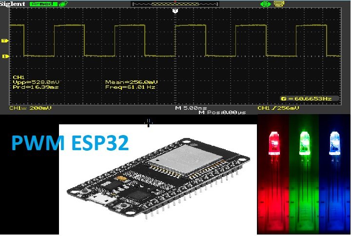
In this tutorial, we will see how to generate PWM or pulse width modulation signals using ESP32 DOIT devkit. Firstly, we will see an introduction to PWM and how to get analog output from ESP32 on any GPIO pin. Secondly, we will see an LED dimming example in which we will get the same PWM signal on different GPIO pins of our ESP board.
We will see how to generate these digital signals using the built-in PWM generator module (LEDC) of ESP32. All GPIO pins of this board can be used to get variable duty cycle and variable frequency output signals. We only need to attach a GPO PIN with an LEDC channel on which we want to get an output signal.
We have a similar guide with MicroPython:
Recommended Components
The following components are used in this project or are helpful for building it with the ESP32.
| Component | How it’s used in this project | Buy on Amazon |
|---|---|---|
| ESP32 Development Board (DevKit V1) | The main microcontroller board that runs the project code and controls all connected parts. | Check Price |
| Micro USB Cable | Connects the ESP32 to your computer to upload code and provide power. | Check Price |
| Breadboard | Lets you build the circuit and connect components without soldering. | Check Price |
| Jumper Wires | Used to wire the ESP32 to the other components on the breadboard. | Check Price |
| 5mm LED | The LED whose brightness is faded up and down using the ESP32 PWM signal. | Check Price |
| Resistor Kit (220 Ω / 4.7k) | A 220 Ω resistor limits current to protect the LED. | Check Price |
As an Amazon Associate we earn from qualifying purchases. Prices and availability are accurate as of the date/time indicated and are subject to change.
PWM Introduction
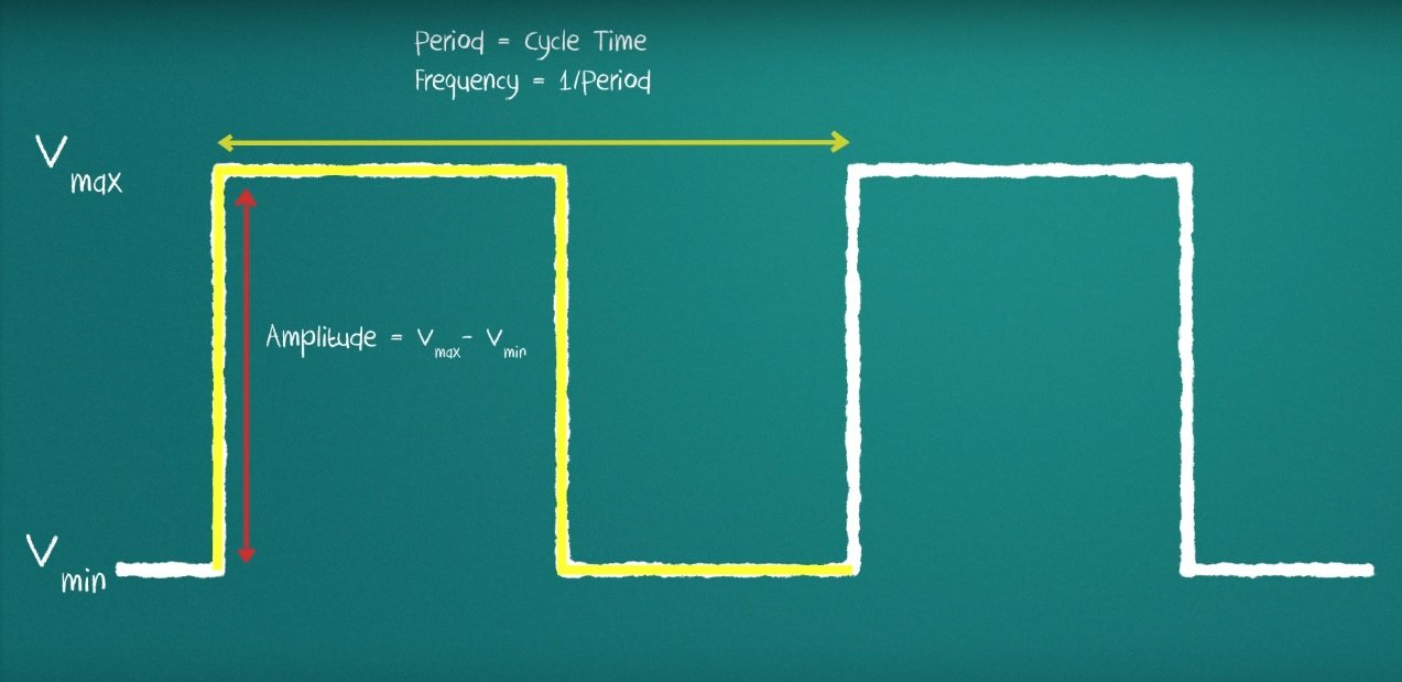
What you can do with PWM? It stands for pulse width modulation and it consists of producing a square wave. you can control the up or high time in a PWM signal. The minimum and maximum voltage are the values that limit the waves oscillation the space between them is called amplitude. A cycle is the interval of the wave where you can find one full repetition the time a cycle takes to finish is called time period. Time period of a signal is
Time period = on time + off time
PWM Frequency
The frequency is 1 over a period which gives you how many cycles are in a time unit. For example, if the timer period of a signal is 20ms, its frequency will be 50Hz where Hz is unit of frequency. It is read a hertz.
Frequency = 1 / timer period
The picture below shows the amplitude and timer period of a waveform.
What is Duty Cycle?
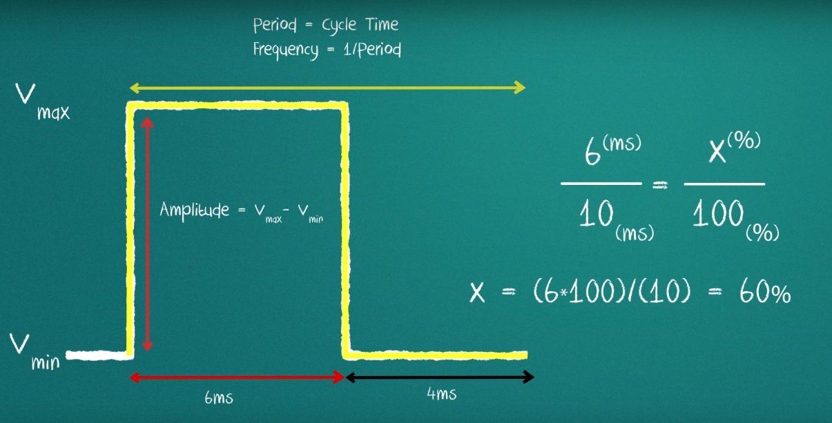
A duty Cycle is an important concept used in pulse width modulation. The duty cycle represents how much of the time in which the signal is high in a total time period.
So the formula for the duty cycle is shown in the given expression below:
Duty Cycle = ( On time of signal / total timer period of signal )
ESP32 PWM Module
Like other built-in modules ADC, Touch panels, and hall effect sensors, the ESP32 board also has an integrated PWM controller in it. It supports sixteen pulse width modulation channels. We can use these channels to get a PWM signal from any GPIO pin. Before that, we need to configure its parameters and PIN assignment. We will that shortly how to set these parameters. In this tutorial, you will learn to use PWM for different applications:
- First, you will learn how to configure these channels to generate signals on ESP32 pins.
- You will learn how to generate fix duty cycle signal.
- You will also see how to generate a variable duty cycle signal.
- In the end, I will show you an example of LED fading with GPIO pin 15 as a digital control signal.
The followings are the mandatory backgrounds concepts to completely understand this tutorial:
Configure ESP32 PWM Channels
If you know Arduino Uno programming, you must see that the analogWrite function is used to generate PWM in Arduino IDE for Arduino related boards. But a different function is used to produce PWM signal for ESP32 in Arduino IDE. Follow these step to set parameters for all channels of pulse width modulation:
- There are 16 LEDC channels available. You need to choose any channel between 0 and 15.
- The second step is to choose the frequency of the digital signal. For example, you can set the frequency like 10,000 hertz, 5000 hertz or any other value you want.
- ESP32 boards support resolution between 1 bit to 16 bits. But remember the frequency and resolution of the PWM signal has an inverse effect on each other. So to achieve maximum frequency, the optimal resolution is 8 bit. You can find more discussion on it in this link.
- We will be using 8-bit resolution, and duty cycle value will vary between 0-255. Duty cycle defines the width of the signal or on time of the signal.
- The last step is to attach the GPIO PIN with a PWM channel of your own choice.
ESP32 PWM APIs in Arduino IDE
Now let’s see how to set these parameters inside the PWM library. Three functions are used for this purpose. One is used to set the PIN with the channel. The second function is used to set the frequency, resolution, and channel of the PWM controller and the third function is used to generate the signal with a specified duty cycle.
ESP32 ledcSetup
This function is used to set the channel number, frequency, and resolution of the output signal. We should pass three arguments as input to this function, channel number, frequency, and the resolution. We use this function inside the setup function only.
uint32_t ledcSetup(uint8_t channel, uint32_t freq, uint8_t resolution_bits);ESP32 ledcAttachPin
This ledcAttachPin attaches any GPIO pins with a channel. This function accepts two arguments. One is the GPIO pin on which we want to get the OUTPUT of the signal and the second argument is the channel on which we produce the signal.
void ledcAttachPin(uint8_t pin, uint8_t channel);ESP32 ledcWrite
This ledcWrite function is used to generate the signal with a specified duty cycle value. The first argument to this function is a channel number and the second value is the required duty cycle. For example, if you set the resolution of an output signal to 8-bit, then the duty cycle value will be between 0-255, and similarly for 10-bit and 12-bit resolution.
void ledcWrite(uint8_t channel, uint32_t duty);ESP32 Change PWM Frequency
This function is used to change the frequency of the output signal. The arguments to this function are channel number, required frequency, and resolution.
uint32_t ledcChangeFrequency(uint8_t chan, uint32_t freq, uint8_t bit_num)ESP32 PWM Example
Now we will see an example to generate a pulse width modulation signal on any GPIO pin, and I will show you signal on the oscilloscope. But the same case can be used as a dimming LED example, or fading LED example. First, we will see an example with fix duty cycle signal on the oscilloscope, and after that, we will see an example of variable duty cycle PWM which can also be used as led dimming example.
I will be using GPIO15 to get this signal and will show this signal on the oscilloscope. Now you just need to connect oscilloscope positive terminal with GPIO pin fifteen and ground terminal of the oscilloscope with the ground of the board. Now, this simple code will generate a PWM signal with a duty cycle of 50%.
PWM Example Sketch
int PWM_FREQUENCY = 1000; // this variable is used to define the time period
int PWM_CHANNEL = 0; // this variable is used to select the channel number
int PWM_RESOUTION = 8; // this will define the resolution of the signal which is 8 in this case
int GPIOPIN = 15 ; // GPIO to which we want to attach this channel signal
int dutyCycle = 127; // it will define the width of signal or also the one time

void setup()
{

ledcSetup(PWM_CHANNEL, PWM_FREQUENCY, PWM_RESOUTION);
ledcAttachPin(GPIOPIN, PWM_CHANNEL);


}

void loop()
{

ledcWrite(PWM_CHANNEL, dutyCycle);

}
This is a simple code to generate a pulse width modulation signal with the duty cycle of 50%. In these line of program, we have define the parameters of the wave form. First we define the frequency of 1000 hertz. We have selected channel zero. But you can select any channel you want from a total of sixteen channels. After that, we specified the resolution of 8 bit. But you can choose any resolution you want. We will be using general purpose input output pin 15 to get the output. At the end of the initialization section, we set the duty cycle to 127. In this example, we are getting a waveform with fix duty cycle.
int PWM_FREQUENCY = 1000;
int PWM_CHANNEL = 0;
int PWM_RESOUTION = 8;
int GPIOPIN = 15 ;
int dutyCycle = 127;
Now in the setup function, we need to use two function ledcSetup and ledcAttach which I have explained above. First procedure will select the channel zero along with the frequency of 1000 hertz and resolution of 8 bits. With 8 bit resolution, we can specify the duty cycle between 0 and (2^8-) = 255. So if we use 255 as a duty cycle parameter, the duty cycle will be 100% and with 127 duty cycle will be 50% and similarly for other values. The second statement will attach the pulse width modulation channel zero to digital pin fifteen.
ledcSetup(PWM_CHANNEL, PWM_FREQUENCY, PWM_RESOUTION);
ledcAttachPin(GPIOPIN, PWM_CHANNEL);
Inside the loop function, we are using only instruction which is to generate a signal with a duty cycle of 127 and you will see it will generate a duty cycle of 50%. The waveform will be high for half of the time and logical low for half of the time and total time period will be inverse of the signal’s frequency. So this ledcWrite function is used to produce PWM signal with a specific duty cycle. you only need to define channel number and duty cycle value as an argument to this function.
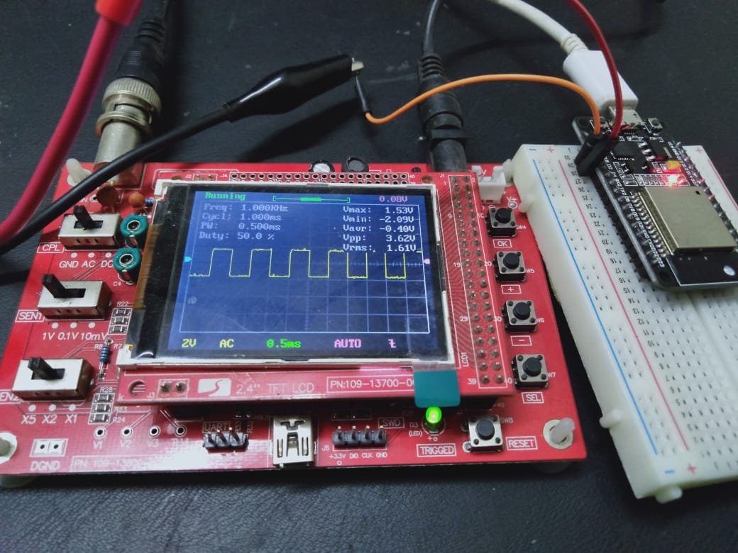
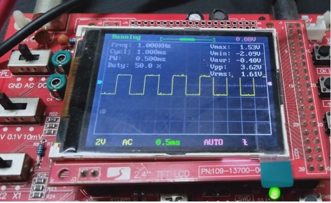
ledcWrite(PWM_CHANNEL, dutyCycle);So When you upload this code to your board and connect oscilloscope across the PIN 15, which types of signal you will get as an output? You will see the digital waveform with the following parameters:
- Frequency = 1000 Hertz
- Time period = 1 ms
- duty cycle = 50%
- on time = 0.5 ms
- off time = 0.5 ms
As you can see in the picture below.
You have now learned how to generate PWM with a required duty cycle. Now we will see the example of creating a variable PWM signal with ESP32 and how we use it for led fading example.
ESP32 Variable Duty Cycle PWM
If your concept is not clear about pulse width modulation, you must be wondering what is meant by the variable duty cycle signal? Variable duty cycle means we want to have digital waveform at the output whose duty cycle will increase from low to high value with some delay. For instance, when we turn on the development board, initially duty cycle will be zero and then it will start increasing with a step of one with some delay. It is very easy to accomplish this task. you just have to change the value of duty cycle inside the ledcWrite function. So the rest of the code which we used in the last example will remain the same except the variable duty cycle part instead of fix. Code for this example is given here.
int PWM_FREQUENCY = 1000;
int PWM_CHANNEL = 0;
int PWM_RESOUTION = 8;
int GPIOPIN = 15 ;

void setup()
{
ledcSetup(PWM_CHANNEL, PWM_FREQUENCY, PWM_RESOUTION);
ledcAttachPin(GPIOPIN, PWM_CHANNEL);
}

void loop()
{

for (int dutyCycle = 0; dutyCycle <= 255; dutyCycle++)
{
ledcWrite(PWM_CHANNEL, dutyCycle);
delay(100);
}
}
This code is similar to the last program except for the loop function part. Inside the loop part, another for loop is used. Inside for loop, starting value of duty cycle is zero and its value keeps increasing with an increment of one with each iteration of for loop. Each iteration occurs after a delay of 100 milliseconds. So you will observe the signal on an oscilloscope with increasing order of pulse width. you can see results in these pictures of different pulse widths.
In the setup() function, ledcSetup() function is called to set up PWM channel, frequency and resoultion. It takes three arguments: the PWM channel (0 in this case), the PWM frequency (1000 Hz), and the PWM resolution (8 bits).
Next, ledcAttachPin() is called to associate a GPIO pin (pin 15) with the PWM channel. This means that PWM signals generated by the LEDC module on this channel will be output on this pin.
void setup()
{
ledcSetup(PWM_CHANNEL, PWM_FREQUENCY, PWM_RESOUTION);
ledcAttachPin(GPIOPIN, PWM_CHANNEL);
}
In the loop() function, a for loop is used to cycle through a range of duty cycles from 0 to 255. On each iteration of the loop, the ledcWrite() function is called to set the duty cycle of the PWM signal on the specified PWM channel to the current value of dutyCycle.
After setting the duty cycle, the delay() function is used to add delay for 100 milliseconds before continuing to the next iteration of the loop. Hence PWM duty cycle will be updated after every 100 milliseconds.
for (int dutyCycle = 0; dutyCycle <= 255; dutyCycle++)
{
ledcWrite(PWM_CHANNEL, dutyCycle);
delay(100);
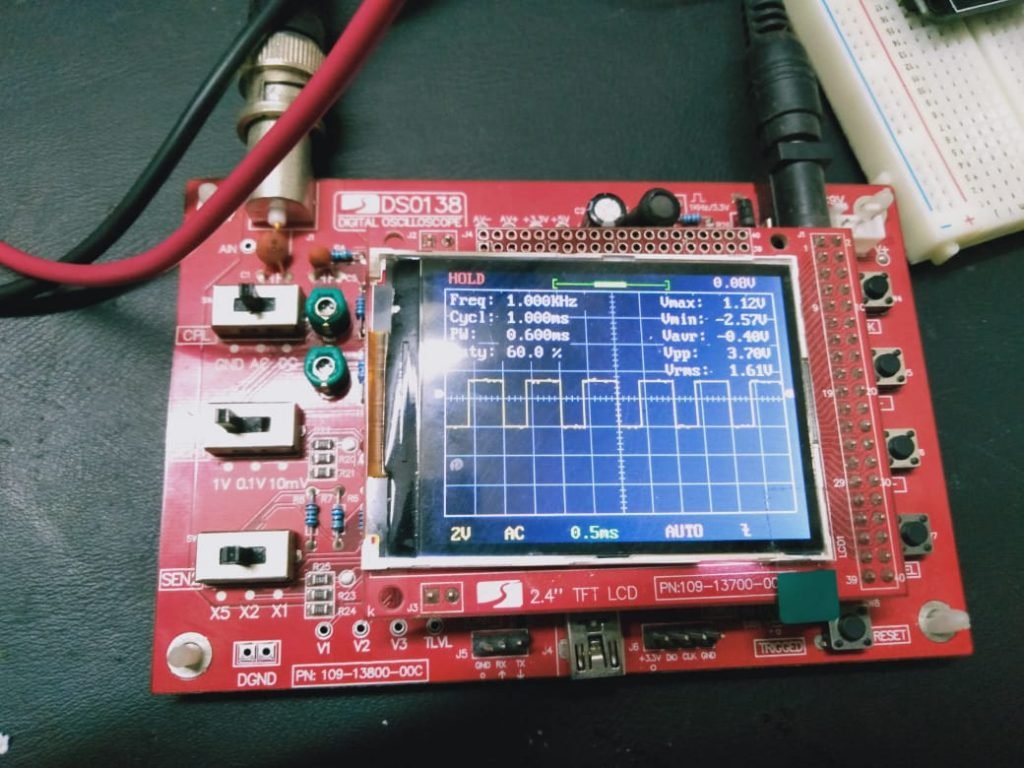
}The following figure shows the PWM output signal from ESP32 with 60% Pulse width or on time:
The following figure shows the PWM output signal from ESP32 with 44% Pulse width or on time:

The following figure shows the PWM output signal from ESP32 with 88% Pulse width or on time:

The following figure shows the PWM output signal from ESP32 with 50% Pulse width or on time:
Video Demo:
You can watch this video demo where you will observe the PWM duty cycle is getting changed after every 100ms.
LED Fading Example ESP32
For LED fading example, you can simply connect an LED with pin number 15 of ESP32 development board and you can upload the same code of variable pulse width to the board. you will see the brightness of LED will be very low at the start and then it start increasing. After some time, LED will glow fully.

ESP32 Get the Same PWM Signal on Different GPIOs
In this section, we will see how to get the same PWM signal output from different GPIO pins. In ESP32 GPIO matrix, we can assign the output of any peripheral to any GPIO pins. Similarly, we can attach the output of any PWM channel to any GPIO pin which can be configured as an output. Because not all pins in ESP32 can be used as digital output pins. Some pins can be used as digital input pins only.
To attach PWM to any output configurable GPIO pin, we use ledcAttachPin() function inside setup() of our Arduino sketch.
The first argument to this function is a pin number and the second argument is a PWM channel to which we want to attach a GPIO pin.
For example, the following lines attached GPIO14 and GPIO15 to PWM channel zero. Through this, we will get the same GPIO signal on both GPIO14 and GPIO15.
int PWM_FREQUENCY = 1000;
int PWM_CHANNEL = 0;
int PWM_RESOUTION = 8;
int GPIOPIN_1 = 15 ;
int GPIOPIN_2 = 14 ;
void setup()
{

ledcSetup(PWM_CHANNEL, PWM_FREQUENCY, PWM_RESOUTION);
ledcAttachPin(GPIOPIN_1 , PWM_CHANNEL);
ledcAttachPin(GPIOPIN_2 , PWM_CHANNEL);
}
ESP32 PWM Applications
Till now we have discussed only how to configure ESP32 PWM channels and get analog output signals from GPIO pins. But this article will be incomplete without knowing what will be the use of this feature.
There are many industrial applications where we can use ESP32 PWM peripheral such as:
- LED Lights Intensity control for street lights
- Motor Controllers
- Induction Motor Drives
- DC Motor Speed Control
you might be interested in other ESP32 tutorials and projects:
Is there a library (.h) file attached to this process? I put the code in so I could do a PWM LED output and Arduino kicks it back because it doesn’t recognize the code. I dont get color changes in the code indicating it sees it differently.
Hello
I would like to help me. Thanks a lot in advance.
After I tried to verify your code I have got the following error:
Arduino: 1.8.9 (Windows 7), Board: “NodeMCU 1.0 (ESP-12E Module), 80 MHz, Flash, Disabled, All SSL ciphers (most compatible), 4M (no SPIFFS), v2 Lower Memory, Disabled, None, Only Sketch, 115200”
C:\Users\Prompt\Documents\Arduino\Test_PWM_ESP32\Test_PWM_ESP32.ino: In function ‘void setup()’:
Test_PWM_ESP32:10:52: error: ‘ledcSetup’ was not declared in this scope
ledcSetup(PWM_CHANNEL, PWM_FREQUENCY, PWM_RESOUTION);
^
Test_PWM_ESP32:11:35: error: ‘ledcAttachPin’ was not declared in this scope
ledcAttachPin(GPIOPIN, PWM_CHANNEL);
^
C:\Users\Prompt\Documents\Arduino\Test_PWM_ESP32\Test_PWM_ESP32.ino: In function ‘void loop()’:
Test_PWM_ESP32:19:33: error: ‘ledcWrite’ was not declared in this scope
ledcWrite(PWM_CHANNEL, dutyCycle);
^
exit status 1
‘ledcSetup’ was not declared in this scope
You should select ESP32 board instead of NodeMCU from tools menu
How many timers LEDC library uses
I have a ESP32C3 Nologo SuperMini and I get the same error during compilation
exit status 1
‘ledcSetup’ was not declared in this scope
does this mean Nologo SuperMini does not support LEDC? or do we need to include some library?