In this tutorial, we are going to look at switch mode power supplies. A switch mode power supply (SMPS) is basically an electronic power supply that efficiently converts electrical power. It transforms power coming from the main source and gives it to the load, like a transformer. It converts current and voltage characteristics. The transistor in this supply switches between low dissipation, full off, and full on states, and therefore it does not take much time in the high transition states. Due to this, there is a minimum waste of energy. By changing the on and off times, we achieve voltage regulation. These switch mode power supplies are usually smaller in size and lighter in weight in comparison to the linear supply. This is mainly because of the smaller size and weight of the transformer it uses.
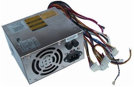
Switch Mode Power Supply
The switching regulators are mostly useful where we require highly efficient and smaller regulators. But their simpler designs can have a poor power factor, noise problems, and they also complicate things. SMPS has many applications in power electronics projects.
Topologies of SMPS
SMPS has different topologies, and there are different specifications and features for each topology. In order to select the most suitable topology, we must know the complexity, drawbacks, basic operation, advantages, and area of usage. We must keep the following features in mind while choosing a topology:
- What is the range of the output voltage as compared to the input voltage?
- The number of outputs that we require?
- Is there any need for dielectric isolation between the input and the output?
- What is the value of the input or output voltage? Is it high?
- What is the value of the input or output current? Is it high?
- What is the maximum primary voltage across the transformer and the maximum duty cycle?
There are several topologies; we mention them below:
- Buck
- Boost
- Buck-Boost
- Cuk/SEPIC
- Flyback
- Forward
- Push Pull
- Half-Bridge
Working of the Different SMPS Topologies
Some of the topologies and their workings are described below:
1. Buck SMPS
It is one of the most common and simplest topologies. It’s ideal use is as a DC-to-DC converter to step down the DC voltage. We can achieve high efficiency and high power levels through it. But a disadvantage of this converter is that the input current is discontinuous. For single-phase applications, we require a single inductor. The Buck converter is also called a ‘chopper circuit’. The figure below shows the circuit diagram as well as the waveforms of current and voltage. We take the output voltage across the load resistor RL. Its frequency is f=1/T.

In this converter, we have a switch at the start of the circuit and in series with the input source. When the switch is on, during the period Ton, the energy goes to the output and to the inductor. The value of the current flowing through the inductor increases. When the switch is off, the current stored in the inductor continues to flow during the period Toff. This current passes through the diode, which we then call a freewheeling diode. During Toff, we apply reverse voltage across the inductor, and the value of current therefore decreases, as we can see in the waveforms. The relationship between the input and output has the following equation:
Vout= D.Vin
Where D = duty cycle.
2. Boost SMPS
This topology is also non-isolating. The buck steps down the voltage, whereas the boost steps up the voltage. The voltage at the output is greater than the voltage at the input. In the continuous conduction mode, it draws current in a continuous manner; therefore, it is best for power factor correction circuits.

In a boost converter, an inductor is at the start of the circuit in series with the input voltage source. During Ton, as the switch opens, the energy flows to the inductor from the input source. The value of the current flowing through the inductor increases. During on-time, the output capacitor supplies the output current to the load. When the switch is off, during the period of Toff, the source applies energy to the load. And the current through the inductor continues to flow, but the value of this current now starts decreasing, as we can see in the waveforms. The relationship between the input and output has the following equation:
Vout = Vin/(1-D)
Where D =duty cycle.
3. Buck-Boost SMPS
The buck boost topology can either step up or step down the voltage according to the requirements. But it has a few disadvantages, such as the inverting of the output voltage, and it also lacks a ground, which makes the driver circuit very complex.

In the buck-boost converter, the components of both the buck and the boost combine together and have an additional control circuit that detects the level of voltages and then acts accordingly.
4. Flyback SMPS
This topology is isolated by using a transformer in the circuit. The circuit is similar to the buck boost circuit. As a transformer is used, different levels of voltage can be achieved. Mostly, it is used for low-power applications. The peak currents can be very high, but the output current should not exceed 10A. One main advantage of this topology is that there is no need for a separate inductor; the transformer itself behaves as an inductor. It has simple circuitry, which makes it cost-effective and easy to use.

In this converter, a switch is added to the primary of the transformer. The transformer provides isolation between the input and output sources. During the Ton period, when the switch is on, the dot side acts as a positive and the diode is reverse biased, due to which the transformer becomes an inductor and stores energy. The value of current in the primary winding of the transformer increases. During this time, the capacitor supplies output current to the load.
When the switch turns off, it induces a negative voltage from the magnetizing current on the dot side. The diode is then in forward bias mode, and the secondary voltage of the transformer becomes equal to the output voltage. The stored energy on the primary side is transferred to the secondary by the flyback action. It charges the capacitor on the output and also gives energy to the load connected.
5. Push Pull Converters:
The push-pull converters contain a set of two primary windings. The transformer core utilization is very efficient in this topology, but there are significant copper losses. Their main advantage is that high power is achievable through them in comparison to the flyback converter. The switching can be difficult because we cannot turn on both switches at the same time. If the switches are turned on at the same time, then a high surge current will destroy the circuit.

A center-tapped transformer is used in it; the primary and secondary are both center-tapped. Two switches are connected with the primary winding, one at each end. These switches operate during alternate half-cycles. Pulsating voltage is produced at the primary of the transformer. The switches are controlled by a control unit or a driver circuit.
Advantages of SMPS over Linear Power Supply:
- The frequency of SMPS is very high; therefore, the transformer is smaller in comparison to the transformer that the linear power supply uses.
- Switching mode supply is also lighter in weight.
- They are more efficient in comparison to linear power supplies because there is no significant heat dissipation or copper loss.
- The variation in voltage is very small when a load is added.
- It has a higher power factor.
- Their noise is in the inaudible human range.
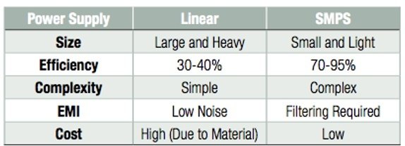
Comparison Between Linear and Switch Mode Power Supplies
The table above summarizes the comparison between linear and switch mode power supplies:
Application-Based Project Using SMPS
Following are the SMPS-based projects for final-year engineering students:
Conclusion
In conclusion, this tutorial provides an in-depth overview of switch mode power supplies. It covers a basic introduction, along with topologies and their workings. At the end, we also discuss the applications of switch mode power supplies to help us better understand the concept. You can utilize it for your project. Hopefully, this was helpful in expanding your knowledge.
You may also like to read:
- MB102 Breadboard Power Supply module – How to use it
- LM386 Low Voltage Audio Power Amplifier
- EL1881 Video Sync Separator Low Power IC
- Auto Power Supply Control System from 4 Different Sources Using PIC Microcontroller
- 18 Volt Transformer less Power Supply
- Power Supply for Electronics Projects
This concludes today’s article. If you face any issues or difficulties, let us know in the comment section below.