This article focuses on a widely-used regulator that serves as a power supply in numerous electronics projects, microcontroller-based projects, and embedded system projects. It is particularly beneficial for engineering students who may not have access to expensive power supplies but still wish to delve into the field of electronics and utilize them effectively within their projects. When undertaking any project, there are various power source options to consider. For instance, if we are working on a project involving integrated circuits, semiconductor devices, or relays, each component may require a specific voltage power supply level to function optimally. For example, a 5-volt power supply would be needed for an AND gate integrated circuit. Below, you will find detailed discussions on the regulator mentioned, accompanied by circuit diagrams for better understanding.
- 7805 voltage regulator
- 7809 voltage regulator
- 7812 voltage regulator
Fairchild’s 78XX series of regulators find their applications in many electronics and embedded system projects. These voltage regulators can deliver up to 1 ampere of current. The “78” in the series represents the maximum current handling capability, which is up to 1 ampere. However, it is important to use proper heat sinks with these regulators for currents up to 1 ampere. The “XX” in the 78XX series represents the voltage output of these voltage regulators. For example, the 7805 voltage regulator has a fixed voltage output of 5 volts. Similarly, the last two digits of 7809 and 7812 indicate the output voltage of these regulators. While this article discusses only three voltage regulators in the 78XX series, there is a full list provided below:
7805, 7806 7809, 7810, 78012, 7815 7818, 7824 voltage regulators with maximum current rating of 1 Ampere.
5, 9, and 12-volt and 1 Ampere Power Supply Circuits
Below are circuit diagrams of five nice twelve-volt and one-ampere power supplies. The circuit uses a 220 to 12-volt transformer to step down the input voltage from 220 volts AC to 12 volts AC. It employs a full bridge rectifier to convert the AC voltage into DC pulsating voltage. A 100uF/25V electrolytic or polar capacitor is used after the bridge rectifier to convert the pulsating output voltage into a constant DC voltage. The circuit utilizes voltage regulators 7805, 7809, and 7812 to provide fixed regulated output voltage. A 0.1uF capacitor is placed at the output of these voltage regulators to avoid voltage fluctuations. We have provided circuit diagrams for all the power supplies mentioned above.
5 Volt and 1 Ampere Power Supply Circuit Diagram
This circuit is designed to provide a 5-volt output with a maximum current of 1 ampere. The input to the circuit is a 220-volt AC power supply. To step down the AC voltage from 220 volts to 12 volts, a 220 to 12-volt transformer is used. The transformer converts the high voltage AC input into a lower voltage AC output of 12 volts.
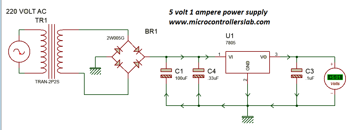
Next, a full bridge rectifier is employed to convert the AC voltage into a pulsating DC voltage. The rectifier consists of diodes that convert the alternating current into a unidirectional flow of current. As a result, the pulsating DC voltage is obtained at the output of the rectifier.
An electrolytic or polar 100uF/25V capacitor is connected in parallel with the output to smoothen the pulsating output voltage and obtain a constant DC voltage. The capacitor minimizes voltage fluctuations or ripples in the output, thereby providing a more stable DC voltage.
After the capacitor, a 7805 voltage regulator is utilized to regulate the voltage to a fixed value of 5 volts. The 7805 voltage regulator ensures that the output voltage remains constant regardless of any fluctuations in the input voltage or changes in the load. To further stabilize the voltage, a 0.1uF capacitor is connected at the output of the voltage regulator.
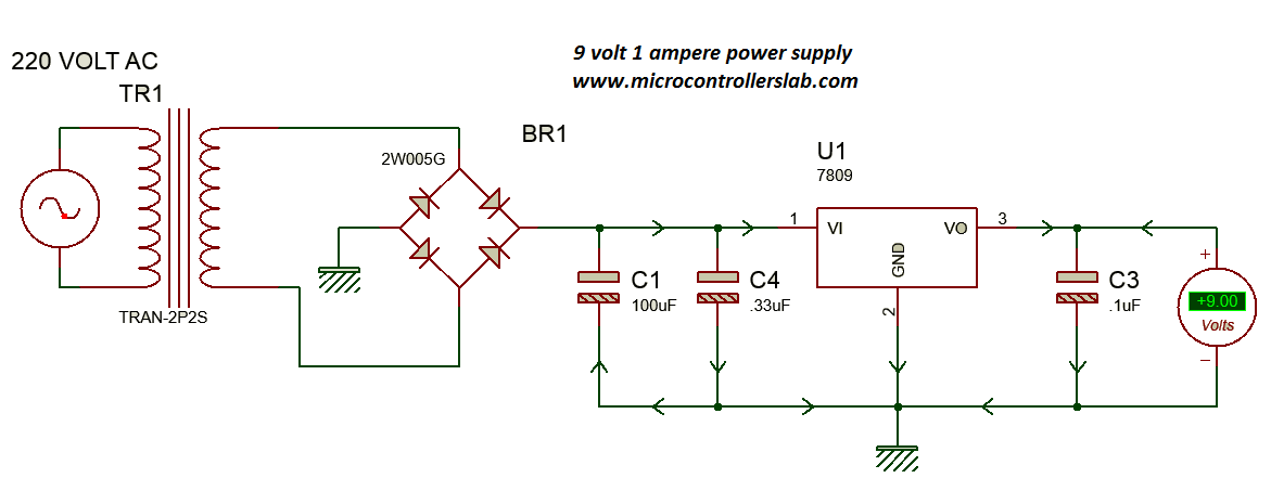
9 Volt and 1 Ampere Power Supply Circuit Diagram
Similar to the previous circuit, this diagram also starts with a 220-volt AC power supply, a 220 to 12-volt transformer, and a full bridge rectifier. The purpose of these components remains the same.
After the rectifier, a 7812 voltage regulator uses instead of the 7805. The 7812 regulator ensures a fixed output voltage of 9 volts. It performs the role of stabilizing the voltage and maintaining a constant output, even in the face of fluctuations.
Again, a 0.1uF capacitor is connected at the output of the voltage regulator to minimize any voltage fluctuations.
12 Volt and 1 Ampere Power Supply Circuit Diagram
This circuit is similar to the two previous ones, but it uses a 7812 voltage regulator instead of the 7805 or 7809. The 7812 regulator maintains a constant output voltage of 12 volts, suitable for projects that require a higher voltage level.
The output of the regulator connects to a 0.1uF capacitor in order to smooth out any voltage fluctuations.

If you are using a battery source instead of AC power supply as a input, then you have no need to use step down transformer, full bridge rectifier and 100uf polar capacitor. These power supply circuits are ideal for various electrical and electronic projects, specifically those involving microcontroller-based projects, embedded systems, and other applications that require precise and regulated power sources.
Conclusion
In conclusion, voltage regulators in the 78XX series, such as the 7805, 7809, and 7812, provide a reliable and cost-effective solution for powering various electronics projects. These regulators are capable of delivering up to 1 ampere of current and offer fixed output voltages of 5, 9, and 12 volts respectively. By utilizing circuit diagrams and explaining the functionality of each component, this article has provided engineering students and electronics enthusiasts with valuable insights on how to create their own power supplies. Whether it’s a 5-volt power supply for an AND gate IC or a 12-volt power supply for higher voltage projects, these circuits ensure stable and regulated power, making them ideal for a wide range of applications.
Related content:
- MB102 Breadboard Power Supply module – How to use it
- Auto Power Supply Control System from 4 Different Sources Using PIC Microcontroller
- Know all about Switch Mode Power Supply
- 18 Volt Transformer less Power Supply
- Transformer less power supply for microcontrollers
- UPS uninterruptible power supply circuit diagram
- LM386 Low Voltage Audio Power Amplifier
HI
Very Intersting. Can You please add a tutorial on power supply without transformer, Its bulky to use anyway.
Thank you
thanks 🙂
Yeah these are bulky power supplies and costly as well. I will try to post article on transformer less power soon.
please help me im 300w digital power supply, and it mist have a pic and lcd, my problem in the program please help me with the program that will display the output voltage when you adjust the potentiometer.
kindly inform me red led 1.03v to3.06/07