MB102 Breadboard Power Supply module is one of the essential and low-cost components in the electronics labs. It powers the circuits and is also used for testing purposes. The small compact module is power efficient and can be operated using an input voltage range of 6.5 Volts to 12 Volts. The module has two voltage regulators which output 3.3 Volts and 5 Volts. Mb-102 also has an onboard capacitor for noise suppression and smoothing the input voltage.

The module is facilitated with a switch to manually turn on/off the module while connected to the power source. It comes with an additional USB connector and berg headers which can also be configured accordingly. The component is useful especially for prototypes and small breadboard circuits.
The post is a quick guide to the pinout, features and specifications, interfacing applications.
Recommended Components
The following parts are used in this article, along with a generic electronics kit that is handy for building and testing the circuit.
| Component | How it’s used | Buy on Amazon |
|---|---|---|
| MB102 breadboard power supply module | The 3.3V/5V breadboard power supply module described in this article. | Check Price |
| Electronic component assortment kit (1390 pcs) | A handy assortment of resistors, capacitors, LEDs, diodes and transistors for building circuits. | Check Price |
| Digital multimeter (AstroAI) | Measures voltage, current, resistance and checks continuity while you build and debug. | Check Price |
| Breadboard | Solderless base for prototyping the circuit. | Check Price |
| Jumper Wires | Make the connections on the breadboard. | Check Price |
As an Amazon Associate we earn from qualifying purchases. Prices and availability are accurate as of the date/time indicated and are subject to change.
Breadboard Power Supply module

The breadboard power supply module consists of:
Power Port & USB Port: The DC power port and USB-A connector are provided to the module to power it up.
Power Switch & LED: A switch is embedded to provide extra control along with an LED to indicate the energizing of the module.
Jumpers: The mb102 breadboard supply module is capable of giving out 3.3 volts or 5 volts to breadboard rails. They can be operated individually.
Berg Headers: The berg headers can be used to output power to other devices as well.
BBPS module Pinout
The following figure shows the pinout diagam of MB102 Breadboard Power Supply module.
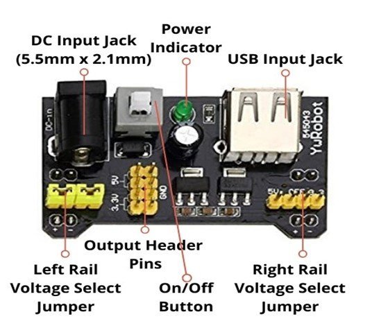
Pin Configuration
The pin configuration of the BBPS module in tabular is described as follows:
| Pin Name | Function |
|---|---|
| Left rail jumper (voltage selection) | 5 VoltsOFF (ground)3.3 Volts |
| Right rail jumper(voltage selection) | 5 VoltsOFF (ground)3.3 Volts |
| Output Headers | 2 output bergs of 3.3 Volts2 output bergs of 5 Volts4 output bergs of GND |
| DC Input jack | 6.5 Volts – 12 Volts Input port |
| USB Input jack | Input port |
Features and Specifications
- Operating Input voltage: 6.5 Volts – 12 Volts
- Output voltage: 3.3 Volts or 5 Volts
- Maximum Output Current: < 700 mA
- Module Dimensions: 5.3cm x 3.5cm
- The module has an on/off switch to control the external input switch.
- Along with the DC port, the Breadboard module has a USB port.
- The USB port provides input to the module to output power to the circuits.
- The module has selectable power rails that can be controlled independently.
- The module can switch between output voltages i.e 3.3V and 5V.
- Plug the BBPS module directly into the breadboard.
- For easiness, the BBPS module also has two pairs of onboard 3.3V and 5V DC output berg headers.
Schemati Diagram
The schematic is provided for the visual and describes the circuitry of the breadboard based power supply module. This schematic diagram becomes handy when any of the components got damaged and we want to replace that component.

How to use BM102 Power Supply Module?
This helpful BBPS module comes in handy in a vast number of projects. It can be interfaced very easily.
To power the Breadboard
To power the breadboard through the BBPS module, mount it on to the breadboard. It should be placed in such a way that the left and right jumpers of the module coincide with the power rails of the breadboard. Connect the input power supply either regulated or unregulated to the DC input jack. Turn on the switch to check the LED. If the module is energized, the LED lights up. Adjust the jumper to the desired output voltage. If you want the bread power rails of 5 volts, adjust the jumper accordingly. The left and right jumpers are two independent channels and can provide different voltages simultaneously.

To power peripherals
Connect similarly as previously explained. Now use female jumpers to connect the berg headers to power up other components and microcontroller units. It is also selectable between 3.3Volts and 5 Volts.
Alternate Options
- XD-42 Dual Channel Breadboard Power Supply
Applications
- Breadboard circuits
- DIY Projects
2D Diagram

Related Components:
- Auto Power Supply Control System from 4 Different Sources Using PIC Microcontroller
- Know all about Switch Mode Power Supply
- 18 volt transformer less power supply
- Transformer less power supply for microcontrollers
- UPS uninterruptible power supply circuit diagram
- Power supply for electronics projects
- LM386 Low Voltage Audio Power Amplifier
- Automatic power source selector circuit using Arduino
- Thyristor Controlled Power for Single Phase Induction Motor
This is a great breadboard power supply… the pic of the schematic is a bit fuzzy. Would it be possible to obtain a higher resolution pic/drawing of the schematic?
I second this!
What is the polarity of the input??
The MB102 has a center-positive DC input it seems. Had me confused for a bit since my power supply outputs center-negative — I use it for audio (guitar pedals).
I found this document. very useful and comprehensive. Thank you