In this tutorial, we will learn to control a stepper motor’s speed and direction using the L293D motor driver IC. The L293D Motor driver IC is a dual-channel H bridge motor driver IC which can be easily used to drive a single stepper motor. We will discuss in detail about this motor driver IC and how to interface it with Arduino. Then, we will show you an Arduino sketch that will control the speed and direction of both unipolar stepper motors (28BYJ-48) and bipolar stepper motors (NEMA 17) every easily. So let us begin.
If you are using Arduino L293D motor driver shield, you can read this article also:
- Arduino L293D Motor Driver Shield Control DC, Servo, and Stepper Motors
- DRV8825 Driver Module for Stepper Motor with Arduino
Recommended Components
The following components are used in this project or are helpful for building it with the Arduino.
| Component | How it’s used in this project | Buy on Amazon |
|---|---|---|
| Arduino Uno R3 | Generates the control signals to the L293D IC that step the bipolar stepper motor. | Check Price |
| Breadboard | Holds the L293D IC and wiring between the Arduino, motor and power supply. | Check Price |
| Jumper Wires | Connect the L293D input pins and stepper coils to the Arduino and supply. | Check Price |
| Bipolar stepper motor (NEMA) | The bipolar stepper motor driven through the L293D H-bridge IC in this tutorial. | Check Price |
As an Amazon Associate we earn from qualifying purchases. Prices and availability are accurate as of the date/time indicated and are subject to change.
Stepper Motors Introduction
Stepper motors are DC brushless and synchronous motors. They rotate in discrete steps of predefined values and are able to rotate both clockwise and anticlockwise. Unlike other DC motors, they provide a precise position control according to the number of steps per revolution for which the motor is designed. That means a complete one revolution of a stepper motor is divided into a discrete number of steps. They are commonly used in CNC machines, Robotics, 2D and 3D printers.
For this guide, we will use a 28BYJ-48 stepper motor as well as NEMA 17 stepper motor to demonstrated both unipolar and bipolar motor control through L293D IC
Unipolar 28BYJ-48 Stepper Motor
The 28BYJ-48 stepper motor is inexpensive and one of the most commonly used stepper motors out there.
28BYJ-48 is a uni-polar 5V stepper motor that takes electrical signals as input and rotates by converting these input signals into mechanical rotation. It consists of 4 stationary coils rated at +5V. These coils are known as a stator and make a ring around the rotor. Because of 5 volts operating voltage, we can easily drive this motor from any microcontroller such as ESP32, ESP8266, Arduino or TM4C123 Tiva Launchpad, etc. It has a 1/64 reduction gear set and therefore moves in precise 512 steps per revolution. These motors are silent in comparison to other DC motors and servo motors. You can achieve positional control easily without needing extra circuitry and components.
Pinout
The following figure shows the pinout diagram of 28BYJ-48 stepper motor. It consists of 5 pins. Out of these 5 pins, four pins are used to provide sequence logic to the coils and one pin is a +5 volts supply pin.
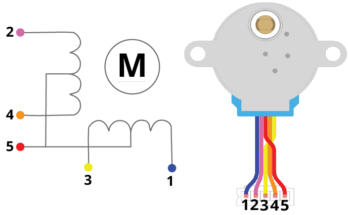
| Pin Number | Coil Number | Colour |
| 1 | 4 | Blue |
| 2 | 2 | Pink |
| 3 | 3 | Yellow |
| 4 | 1 | Orange |
| 5 | VCC | Red |
Coil 1-Coil 4: These are coils used to control the step sequence of the stepper motor. One end of each coil is connected with +5V and the other end will be connected with the driver output.
Vcc: Used to apply +5 volt supply to the stepper motor. This voltage appears across the coils when a specific coil is ground through a control sequence.
For more information reagarding 28BYJ-48 refer to the following guide: 28BYJ-48 5 volt Stepper Motor Guide
NEMA 17 Stepper Motor
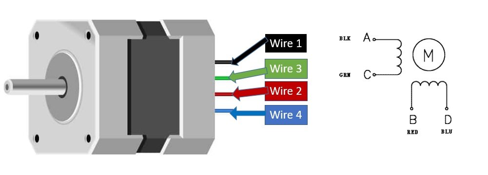
NEMA 17 is a bipolar stepper motor rated at 12V. In NEMA 17 all pins are connected internally with the coil. To make the movement we need to magnetize the coil. The rotation of the motor requires the magnetic field to make a single step. The time required to make the coil fully magnetic depends on the induction of the coil.
Internally to control the stepper motor we will have to use the green and black pair. The second pair will be of red and blue.
Features:
- Its rated voltage is 12V
- Phase current is 2.2A
- The Holding torque is equal to 40N.cm
- One step angle will be of 1.8 Deg.
- Total steps for each resolution will be 200.
- 4-wire and 8-inch lead
- Number of phases are 4
- Total inductance by each phase will be 2.8 mH
- The resistance of the coil is 1.5 Ohm per coil.
L293D Motor Driver IC
L293D IC is known as a motor driver. It is a low voltage operating device like other ICs. L293D provides the continuous bidirectional Direct Current to the Motor. The Polarity of current can change at any time without affecting the whole IC or any other device in the circuit. L293D has an internal H-bridge installed for two DC motors or a single stepper motor.
H-Bridge is an electrical circuit that enables the load in a bidirectional way. L293D bridge is controlled by external low voltage signals. It may be small in size, but its power output capacity is higher than our expectation. It could control any motor speed and direction with a voltage range of 4.5 – 36 Volts. Its diodes also save the controlling device and IC from back EMF. To control the max 600mA amount of current an internal “Darlington transistor sink” installed in it, which could be used to control a large amount of current by providing a small amount of current. It has also internal “pseudo-Darlington source” which amplifies the input signal to control the high voltage DC motor without any interception.
Pinout
The diagram below shows the pin out of L293D IC:

Enable Pins
- Pin1 (Enable): Pin 1 is known as the enable pin. It has a major effect on Input and output. If there is High logical signal on enable pin (EN) then there will be input and output between pin 2,3,6 & 7 (Input 1, Output 1, Input 2 & Output 2)
- Pin9 (Enable): Pin 9 is also the same as Pin 1. It controls the input and output signals. Pin 9 Controls the connection between Input 3, Input 4, Output 3 and Output 4. It also enables the connection when the logic signal will be High (1).
Input Pins
- Pin2 (Input 1): Mostly input means where we provide the input to give the output. But here Input 1 means which polarity we want to give at Output 1.
- Pin7 (Input 2): Input 2 will attach to the control button or device to control the Output 2 just like Input 1.
- Pin10 (Input 3): Input 3 will control the output polarity of the Pin 11 (Output 3) by logic signals.
- Pin15 (Input 4): Pin 15 will control the output polarity of the Pin 14 (Output 4) by logic signals.
Output Pins
- Pin3 (Output 1): Output 1 is the input of the first motor/Motor 1. It attaches to its one end.
- Pin6 (Output 2): Output 2 will attach to the input of the first motor/Motor 1. It will attach to its second end.
- Pin11 (Output 3): Output 3 will be connected to the one end of the second motor.
- Pin14 (Output 4): Pin 14 will attach to the second end of the second motor.
Power Pins
- Pin8 (Vcc): Pin8 is the voltage pin for Motor. It will decide how much power we are going to attach the Motor. This Power should not be more than 36 volts and should not be less than 4.5 volts.
- Pin16 (Vcc): Pin 16 will the Power we will provide to the L293D to activate it or to turn it on. The power level of Pin 16 should be 4.5 – 7 Volts. Voltage more than 7 will burn the IC
- Pin4 (Ground) and Pin5 (Ground) : The ground pins will attach to the ground of the circuit.
- Pin12 (Ground) and Pin13 (Ground): These will attach to the common ground with all other grounds.
Control Pins
The L293D IC features both speed and direction control pins to control two DC motors or a single stepper motor simultaneously.
Direction Control Input Pins
The direction control pins are the four input pins (Pin2 IN1, Pin7 IN2, Pin10 IN3, Pin15 IN4) on the IC.
Through these input pins we can determine whether to move the motor forward or backwards. IN1 and IN2 control motor A’s spinning direction whereas IN3 and IN4 control motor B’s spinning direction. The table below shows the logic signals required for the appropriate spinning action for motor A.
| IN1 | IN2 | Motor Action |
| 1 (HIGH) | 1 | OFF |
| 1 | 0 (LOW) | Backward |
| 0 | 1 | Forward |
| 0 | 0 | OFF |
As seen from the table, whenever one of the inputs is in a HIGH state (5V) then the motor will spin. Otherwise, when both the inputs are LOW (ground) state or both are in HIGH state then the motor stops. In order for motor A to spin forward, IN1 should be LOW and IN2 should be HIGH. For backwards motion, IN1 should be HIGH and IN2 should be LOW. Motor B is also controlled in a similar way.
Speed Control Pins
The speed control pins pin1 (EN1,2 or ENA) and pin 9 (EN3,4 or ENB) on the IC, control the speed of the dc motor and turn it ON and OFF.
EN1,2 controls the speed of one motor and EN3,4 controls the speed of the other motor. If both of the pins are in a logic HIGH (5V) state, then both the motors are ON and spinning at maximum speed. If both of the pins are in a logic LOW (ground) state, then both the motors are OFF. Through the PWM functionality, we can also control the speed of the motor.
You can know more about the L293D motor drivers here:
Features
- L293D could be used to control the two motors at the same time.
- It has the ability to control the speed by using the enable pin.
- The direction is also easy to change.
- Voltage supply range is higher than other IC. Voltage range between 4.5-36 volts can easily handle by the IC to the motor.
- The motor has a maximum continuous range of current close to 600mA but the maximum peak current range is 1.2A
- It has an automatic shutdown system on thermal condition.
- Its working range is from 0 – 70 degree which is much higher for any small-sized IC.
- It has an internal back emp protection for IC and the controlling device.
Interface L293D DC Motor Driver IC with Arduino and 28BYJ-48 Stepper Motor
We will require the following equipment.
Required Equipment :
- Arduino
- L283D Motor driver IC
- 28BYJ-48 stepper motor
- Breadboard
- Connecting Wires
For which ever stepper motor you are using refer to its datasheet to find the correct coloured wires to differentiate the coil1, coil2, coil3 and coil4 wires. This will enable us to properly connect the motor with the OUT1, OUT2, OUT3 and OUT4 pins of the driver IC.
Assemble the circuit as shown in the connection diagram below.
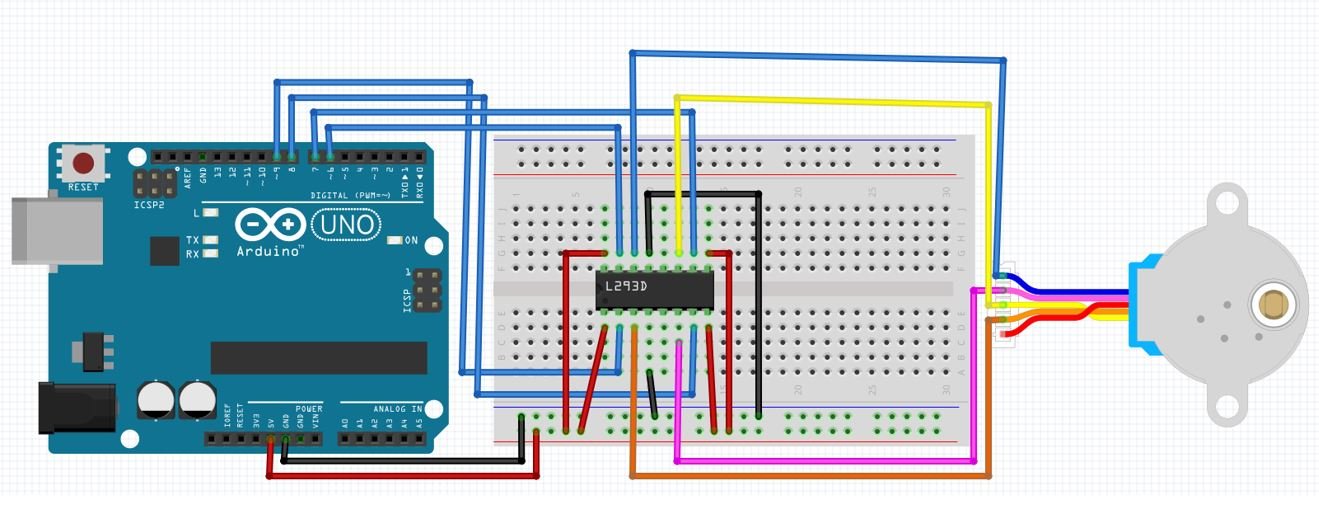
Connect 5V from Arduino with pin8 and pin16. These will power up both the motor and the driver IC. Additionally, connect the enable pins pin1 (ENA) and pin9 (ENB) with 5V as well. This will ensure that the stepper motor stays enabled. Connect all the common grounds together.
Then, we will connect the input pins Pin2 (IN1), Pin7 (IN2), Pin10 (IN3) and Pin15 (IN4) with digital pins of the Arduino UNO. We have used GPIO9, GPIO8, GPIO7 and GPIO6 respectively to connect with each of the input pins of the motor driver IC.
Connect the stepper motor’s coloured wires with correct output pins of the driver IC. In our case, orange wire is coil1 and pink wire is coil2 hence they will connect with Pin3 (OUT1) and Pin6 (OUT2) respectively. Likewise, the yellow wire is coil3 and the blue wire is coil4 hence they will connect with Pin11 (OUT3) and Pin14 (OUT4) respectively.
Interface L293D DC Motor Driver IC with Arduino and NEMA 17 Stepper Motor
We will require the following equipments.
Required Equipment:
- Arduino
- L283D Motor driver IC
- NEMA 17 stepper motor
- External 12V power supply
- Breadboard
- Connecting Wires
For which ever stepper motor you are using refer to its datasheet to find the correct coloured wires to differentiate the coil1, coil2, coil3 and coil4 wires. This will enable us to properly connect the motor with the OUT1, OUT2, OUT3 and OUT4 pins of the driver IC.
Assemble the circuit as shown in the connection diagram below.
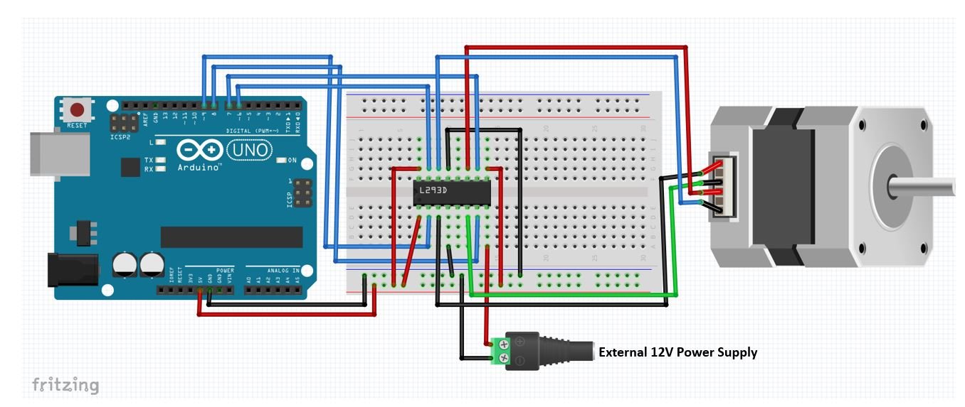
Connect 5V from Arduino with pin8. This will power up the driver IC. Connect positive terminal of 12V power supply with pin8 and negative terminal with common ground. Additionally, connect the enable pins pin1 (ENA) and pin9 (ENB) with 5V as well. This will ensure that the stepper motor stays enabled. Connect all the common grounds together.
Then, we will connect the input pins Pin2 (IN1), Pin7 (IN2), Pin10 (IN3) and Pin15 (IN4) with digital pins of the Arduino UNO. We have used GPIO9, GPIO8, GPIO7 and GPIO6 respectively to connect with each of the input pins of the motor driver IC.
Connect the stepper motor’s coloured wires with correct output pins of the driver IC. In our case, black wire is coil1 and green wire is coil2 hence they will connect with Pin3 (OUT1) and Pin6 (OUT2) respectively. Likewise, the red wire is coil3 and the blue wire is coil4 hence they will connect with Pin11 (OUT3) and Pin14 (OUT4) respectively.
Arduino Sketch: Controlling Stepper Motor using L293D Motor Driver IC
Open your Arduino IDE and go to File > New. A new file will open. Copy the code given below in that file and save it.
This basic sketch will show us how to control a stepper motor’s speed and direction of rotation using the L293D motor driver IC.
#include <Stepper.h>

const int steps_per_rev = 200; //Set to 200 for NIMA 17 and set to 48 for 28BYJ-48
#define IN1 9
#define IN2 8
#define IN3 7
#define IN4 6

Stepper motor(steps_per_rev, IN1, IN2, IN3, IN4);


void setup()
{
  motor.setSpeed(50);
  Serial.begin(115200);
}

void loop()
{
  Serial.println("Rotating Clockwise...");
  motor.step(steps_per_rev);
  delay(500);

  Serial.println("Rotating Anti-clockwise...");
  motor.step(-steps_per_rev);
  delay(500);
}
How the Code Works?
Firstly, we will include the Stepper.h library. This library provides useful functions that make it easy to control the stepper motor.
#include <Stepper.h>The next step is to define the steps per revolution. This is the number of steps our motor requires to move one complete revolution. If using NEMA 17 set the value to 200. If using 28BYJ-48 instead set the value to 48.
const int steps_per_rev = 200; //Set to 200 for NIMA 17 and set to 48 for 28BYJ-48Next, we will define the input pins of the motor connections with the Arduino board. As you can see we have used the digital pins 9,8,7 and 6 to connect with IN1, IN2, IN3 and IN4 respectively. However, you can use any other suitable Arduino digital pins as well.
#define IN1 9
#define IN2 8
#define IN3 7
#define IN4 6
Now we will create an instance of the Stepper library called motor() and pass the steps per revolution and the individual motor input pins as arguments. Make sure you specify the input pins in their correct sequence. It is IN1, IN3, IN2, and IN4 for 28BYJ-48 stepper motor.
Stepper motor(steps_per_rev, IN1, IN2, IN3, IN4);
Inside the setup() function, Serial.begin() is used to establish the serial connection between the development board at a baud rate of 115200. We will use the setSpeed() method on the motor instance and pass the speed of the motor in rpm as an argument inside it. In our case we are setting the stepper motor speed to 50 revolutions per minute.
void setup()
{
  motor.setSpeed(50);
  Serial.begin(115200);
}
Inside the loop() function, we will first rotate the motor clockwise by using the step() method and passing the steps per revolution as the argument inside it. Hence the motor will rotate at steps of 200 per revolution. Likewise, to rotate the motor anti-clockwise we will pass the steps per revolution with a negative sign inside the step() method. Between the two types of rotations we will have a delay of 0.5 second. Additionally, we will print the type of rotation in the serial monitor as well.
void loop()
{
  Serial.println("Rotating Clockwise...");
  motor.step(steps_per_rev);
  delay(500);

  Serial.println("Rotating Anti-clockwise...");
  motor.step(-steps_per_rev);
  delay(500);
}
Demonstration
To see the demonstration of the above code, upload the code to Arduino. Before uploading the code, make sure to select Arduino UNO from Tools > Board.

Also, select the correct COM port to which the Arduino board is connected from Tools > Port.
Once the code is uploaded to your board, the motor will start rotating.
The stepper motor will start rotating clockwise and then anti-clockwise repeatedly.
In your Arduino IDE, open up the serial monitor and you will be able to see the status of the motor rotation as well.

Video Demo:
You can also read a similar guide to control DC motor with L293D and Arduino:
You may also like to read these projects where we have learned to control stepper motor from a web sever
- ESP32 Stepper Motor WebSocket Web Server using Arduino IDE
- ESP8266 NodeMCU Stepper Motor WebSocket Web Server using Arduino IDE
You may also like to read other stepper motor tutorials: