In this tutorial, we will learn to interface a stepper motor with TM4C123 Tiva Launchpad. There are many options available for stepper motors. But in this tutorial, we will use an inexpensive 28BYJ-48 stepper motor for interfacing with TM4C123. Because it comes with a UL2003 driver. Moreover, it is a low-cost solution to learn about stepper motors control and working. But the concepts learned with this type can be easily applied to other high torque industrial stepper motors also. For programming of TM4C123 Tiva Launchpad, we will use Keil MDK for ARM.

Recommended Components
The following components are used in this project or are helpful for getting started with TM4C123 Tiva C LaunchPad development.
| Component | How it’s used in this project | Buy on Amazon |
|---|---|---|
| TM4C123G Tiva C LaunchPad | The Tiva C board driving the stepper sequence. | Check Price |
| Micro USB Cable | Connects the LaunchPad’s onboard debugger to your PC for programming and power. | Check Price |
| 28BYJ-48 Stepper Motor + ULN2003 Driver | The unipolar stepper motor and its driver board used in this project. | Check Price |
| Breadboard | Solderless breadboard for building the circuit. | Check Price |
| Jumper Wires | For wiring the driver board to the LaunchPad. | Check Price |
As an Amazon Associate we earn from qualifying purchases. Prices and availability are accurate as of the date/time indicated and are subject to change.
Pre-requisites:
- How to Download and Install Keil uVision for ARM and 8051
- Getting started with Keil uVision: Write your first Program for Tiva LaunchPad
Stepper motors Introduction
As its name suggests, stepper motor rotates in discrete steps of predefined values. These are DC brushless and synchronous motors. Unlike other DC motors, they provide a precise position control according to the number of steps per revolution for which motor is designed. That means a complete one revolution of a stepper motor is divided into a discrete number of steps. You will find their enormous use in CNC machines, Robotics, 2D and 3D printers.
As discussed earlier, in this TM4C123 stepper motor tutorial, we will use a 28BYJ-48 stepper motor and control it through ULN2003 motor driver.
28BYJ-48 stepper motor
This is the most commonly used stepper motor in low power industrial and mostly famously in hobbyist projects. 28BYJ-48 is a unipolar 5 coil stepper motor with operating voltage of 5V. That means 28BYJ-48 has four sequences of coils arrangement and these coils can be powered with 5 volts. Because of 5 volts operating voltage, we can easily drive this motor from any microcontroller such as TM4C123 Tiva Launchpad.
This stepper motor has a stride angle of 5.625 degree. That means 28BYJ-48 will complete one revolution in (360/5.625) 64 steps by taking one step at a time and in one step it covers 5.625 degree distance. But this stepper motor can also be used in full step mode. In full step mode, the angle of each step is 11.25 degrees. That means the motor completes its one revolution in 32 steps ( 360/11.25).
Therefore, In order to move one step forward or backward, the coils of the motor engerizes with a particular sequence.
We will discuss sequences required to control steps of the stepper motor in coming sections.
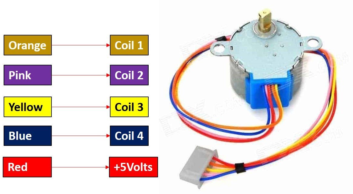
28BYJ-48 stepper motor Pinout
The following figure shows the pinout diagram of 28BYJ-48 stepper motor. It consists of 5 pins. Out of these 5 pins, four pins are used to provide sequence logic to the coils and one pin is +5 volts supply pin.
Pin Configuration Details
| Pin | Name | Color | Functionality |
|---|---|---|---|
| 1 | Coil1 | Orange | These are coils used to control the step sequence of the stepper motor. One end of each coil is connected with +5V and the other end will be connected with ULN2003 driver output. |
| 2 | Coil2 | Pink | |
| 3 | Coil3 | Yellow | |
| 4 | Coil4 | Blue | |
| 5 | Vcc | Red | Used to apply +5 volt supply to the stepper motor. This voltage appears across the coils when a specific coil is ground through a control sequence. |
ULN2003 Stepper Motor Driver Module
Now the first question which comes to your mind is why do we need a ULN2003 driver to drive stepper motors? This is because the current consumption of 28BYJ-48 is around 240mA. That means the current required to drive coils by applying a sequence of control signals is also almost 200mA. GPIO pins of TM4C123 Tiva Launchpad can not provide current of this magnitude. Therefore, we need a ULN2003 driver which translates low current output of TM4C123 GPIO pins into higher current that meets the requirement of stepper motor control signals.
Stepper Motor Driver Module Pinout
ULN2003 driver IC consists of 7 darlington pair transistor outputs. Each output can drive 500mA and 50V load. The input to each 7 darlington pair transistor can be a signal from the microcontroller such as TM4C123GH6PM microcontroller. To drive a stepper motor, this driver board used only four outputs. The following diagram shows the ULN2003 motor driver board and details of their components:
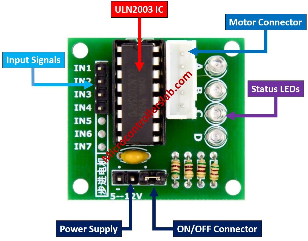
1N1 to IN4: These are input pins used to provide control signals to stepper motor such as control sequences. We will connect these pins with GPIO pins of TM4C123 Tiva Launchpad.
Vcc and GND: Vcc is a power supply pin and it is used to provide 5 volts power to the stepper motor from an external power source. Furthermore, TM4C123 microcontroller does not have an onboard 5 volts signal. Therefore, we will need to provide power from an external power source. Additionally, the 28BYJ-48 stepper motor requires 240mA current to operate and it also consumes power at an idle condition. Therefore, it is recommended not to power the 28BYJ-48 stepper motor directly from any microcontroller instead use an external 5 volts power supply.
Motor Connector Header: This connector is used to connect a stepper motor. It provides output from four Darlington pair transistors.
Connection Diagram 28BYJ-48 stepper motor and TM4C123G Tiva Launchpad
So far in this tutorial, we learned everything about stepper motor and its driver board. Now make connections with 28BYJ-48, ULN2003 and TM4C123 Launchpad according to this schematic diagram.
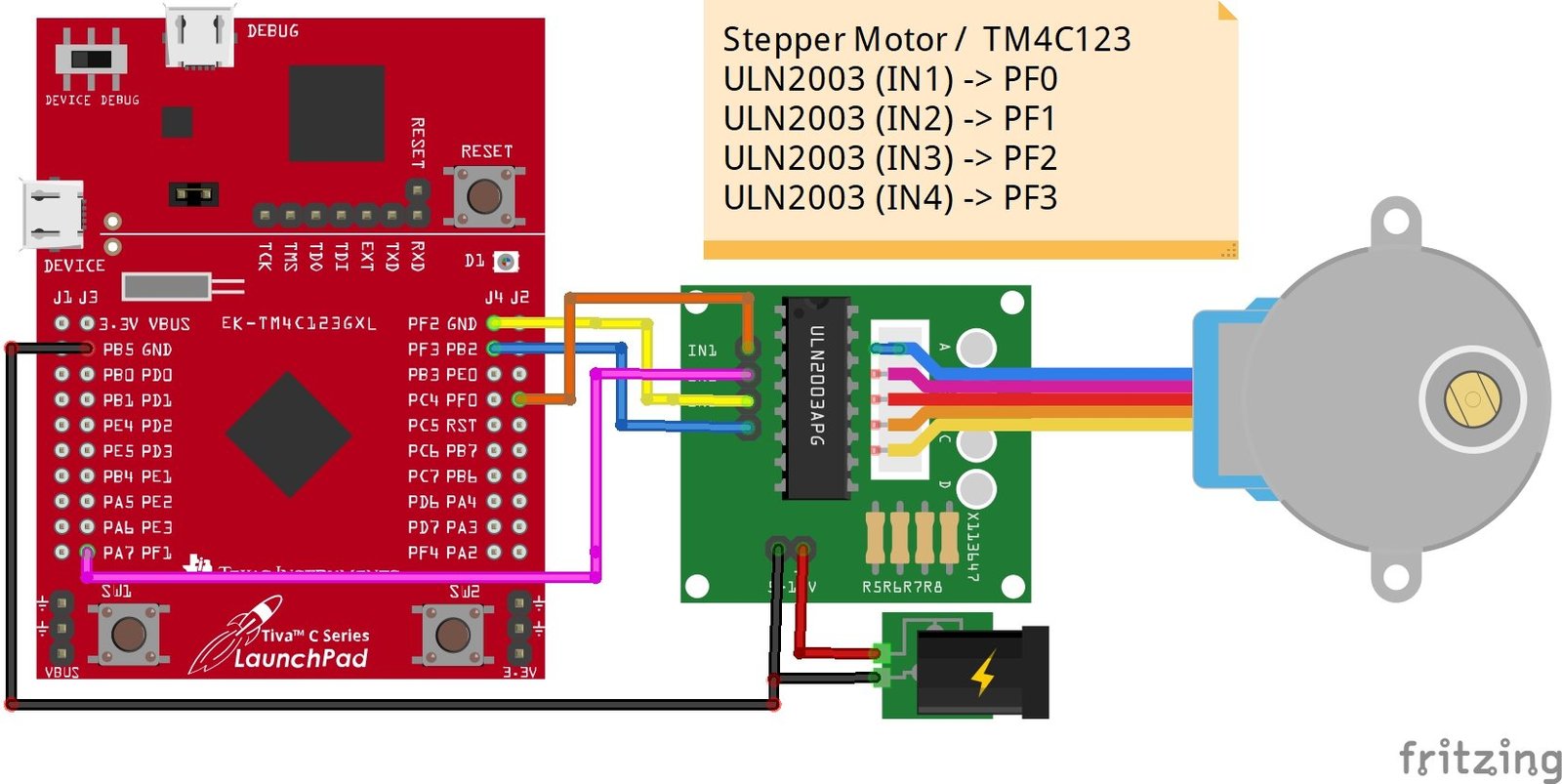
Note: It is recommended to power 28BYJ-48 stepper motor with an external 5-volt power source having at least 300mA current output. Furthermore, TM4C123 does not have a 5-volt signal. Therefore, we should use an external power source.
Stepper Motor / TM4C123
- (IN1) -> PF0
- (IN2) -> PF1
- (IN3) -> PF2
- (IN4) -> PF3
Stepper Motor Sequence Control Logic TM4C123
There are three ways to provide control sequence to coils of unipolar stepper motor such as full-drive, half drive and wave-drive. It is beyond the scope of this tutorial to provide in-depth details of these types. However, we will discuss the control sequence of all these three types.
Full Drive Sequence Mode
In this mode, two coils are energized at a time that means two windings of stepper motor energized together. Therefore, motor runs at full torque. We apply this sequence to input pins of the stepper motor through a UNL2003 driver.
| Step | Blue | Pink | Yellow | Orange |
|---|---|---|---|---|
| 1 | 1 | 1 | 0 | 0 |
| 2 | 0 | 1 | 1 | 0 |
| 3 | 0 | 0 | 1 | 1 |
| 4 | 1 | 0 | 0 | 1 |
Half Drive Sequence Mode
In this mode, we control the phases or coils with alternate one and two phase control as shown in the table below. But, in this mode, motor runs at low torque.
| Step | Blue | Pink | Yellow | Orange |
|---|---|---|---|---|
| 1 | 1 | 0 | 0 | 0 |
| 2 | 1 | 1 | 0 | 0 |
| 3 | 0 | 1 | 0 | 0 |
| 4 | 0 | 1 | 1 | 0 |
| 5 | 0 | 0 | 1 | 1 |
| 6 | 0 | 0 | 0 | 1 |
| 7 | 1 | 0 | 0 | 1 |
| 8 | 1 | 0 | 0 | 0 |
Wave Drive Mode
Like full-drive mode, only one coil is turned on at a time but with a drive sequence as shown below. The only advantage of this method is that a stepper motor consumes less power.
| Step | Blue | Pink | Yellow | Orange |
|---|---|---|---|---|
| 1 | 1 | 0 | 0 | 0 |
| 2 | 0 | 1 | 0 | 0 |
| 3 | 0 | 0 | 1 | 0 |
| 4 | 0 | 0 | 0 | 1 |
Input sequences as shown in the above tables are provided through GPIO pins of microcontrollers such as TM4C123 Tiva Launchpad.
Stepper Motor Control Code TM4C123G
This code uses the wave drive mode to drive the stepper motor. This code is written using Keil uvision. If you don’t know how to use Keil MDK for ARM, you can check these articles:
/* This program drives the stepper motor in full rotation using wave drive mode*/
/*include register definition file of TM4C123GN6PM microcontroller */
#include "TM4C123GH6PM.h"

/* function prototype of milisecond delay routine */
void Delay_ms(int n);

int speed = 5; //* Vary the speed between 1-10 ms delay
int i = 0;

/* Main function to drive motor */
int main(void)
{

    SYSCTL->RCGCGPIO |= 0x20;   /*Enable clock to PORTF */

    /* GPIOF->DATA PF3,PF2, PF1, PF0 pin initialization*/
    GPIOF->DIR |= 0x0F;         /* GPIOF->DATA  PF3,PF2, PF1, PF0as output */
    GPIOF->DEN |= 0x0F;         /* GPIOF->DATA  PF3,PF2, PF1, PF0 as digital pins */

	while(1)
{

	 for(i=0; i<250; i++) // take 250 steps to complete one revolution
{
		// apply full drive clockwise rotation sequence
	  GPIOF->DATA = 0x08;
    Delay_ms(4);
    GPIOF->DATA = 0x04;
    Delay_ms(4);
    GPIOF->DATA = 0x02;
    Delay_ms(4);
    GPIOF->DATA = 0x01;
    Delay_ms(4);
}
}

}
/* Generates a delay in number of miliseocnds wit system clock of 16MHz */
void Delay_ms(int n)
{
    int a, b;
    for(a = 0 ; a < n; a++)
        for(b = 0; b < 3180; b++)
            {} /* execute NOP for one milisecond */
}

/* This function is called by the startup assembly code to perform system specific initialization tasks. */
void SystemInit(void)
{
    /* Grant coprocessor access */
    /* This is required since TM4C123G has a floating point coprocessor */
    SCB->CPACR |= 0x00f00000;
}
How Does Code Work?
This code is used to drive a stepper motor connected to a TM4C123 Tiva Launchpad in a full rotation using the “wave drive” mode. Below is an explanation of the different sections of the code:
1. Include Register Definitions for TM4C123
#include "TM4C123GH6PM.h"This line includes the header file that contains the register definitions for the TM4C123 microcontroller. It allows access to the specific registers to control GPIOs and other peripherals.
2. Function Prototype for Delay
void Delay_ms(int n);This is a function prototype for a delay function that generates a delay in milliseconds. This function will be used to control the speed of the stepper motor’s rotation.
3. Global Variables
int speed = 5; // Vary the speed between 1-10 ms delay
int i = 0;speedvariable controls the speed of the motor by specifying the delay between steps.iis used as a loop counter for controlling the number of steps the motor takes.
4. Main Function: Initializing GPIO and Motor Control
int main(void)
{
    SYSCTL->RCGCGPIO |= 0x20;   /* Enable clock to PORTF */

    /* GPIOF->DATA PF3, PF2, PF1, PF0 pin initialization */
    GPIOF->DIR |= 0x0F;         /* Set PF3, PF2, PF1, PF0 as output pins */
    GPIOF->DEN |= 0x0F;         /* Enable digital function on PF3, PF2, PF1, PF0 */
This section initializes the clock and GPIO pins:
SYSCTL->RCGCGPIO |= 0x20;enables the clock for Port F.GPIOF->DIR |= 0x0F;sets pins PF3, PF2, PF1, and PF0 as output pins (needed to control the stepper motor phases).GPIOF->DEN |= 0x0F;enables the digital function for those pins.
5. Motor Control Loop
    while(1)
    {
        for(i = 0; i < 250; i++) // take 250 steps to complete one revolution
        {
            // apply wave drive clockwise rotation sequence
            GPIOF->DATA = 0x08; // Step 1: Activate PF3
            Delay_ms(4);
            GPIOF->DATA = 0x04; // Step 2: Activate PF2
            Delay_ms(4);
            GPIOF->DATA = 0x02; // Step 3: Activate PF1
            Delay_ms(4);
            GPIOF->DATA = 0x01; // Step 4: Activate PF0
            Delay_ms(4);
        }
    }
}
The while(1) loop continuously rotates the stepper motor. The for loop inside it runs for 250 steps, which completes one full revolution of the motor.
GPIOF->DATA = 0x08;sets PF3 high and the others low, activating the first phase of the motor.- The following steps rotate the motor by successively activating PF2, PF1, and PF0, causing the motor to step in the clockwise direction.
- The
Delay_ms(4);function is used to control the timing between each step, which affects the motor’s speed.
6. Delay Function
void Delay_ms(int n)
{
    int a, b;
    for(a = 0 ; a < n; a++)
        for(b = 0; b < 3180; b++)
            {} /* execute NOP for one millisecond */
}
This function creates a delay of approximately n milliseconds. It consists of nested loops that run a no-operation (NOP) instruction. This NOP approximates the delay, which is calibrated to the system clock of 16 MHz.
7. System Initialization Function
void SystemInit(void)
{
    /* Grant coprocessor access */
    /* This is required since TM4C123G has a floating point coprocessor */
    SCB->CPACR |= 0x00f00000;
}
This function is called at startup to perform system-specific initialization tasks. It grants access to the floating-point coprocessor, which is required by the TM4C123 microcontroller.
In this code, PORTF pins PF0, PF1, PF2 and PF3 are used to provide input sequence to stepper motor driver board. These pins are configured as digital output pins. If you don’t know how to configure GPIO pins of TM4C123, you can read these tutorials:
Hardware Demo
This video shows that stepper motor rotates in both clockwise and ant-clockwise direction. In order to change the above code of TM4C123 for anti-lclock wise rotation, just apply the sequence in opposite order.
Conclusion
In conclusion, interfacing the 28BYJ-48 stepper motor with the TM4C123 Tiva Launchpad provides an excellent opportunity to understand the fundamental concepts of stepper motor control. By using the UL2003 driver, this low-cost setup offers a practical learning experience that can be easily translated to controlling other more powerful industrial stepper motors. With the help of Keil MDK for ARM, programming the TM4C123 becomes straightforward, allowing for efficient motor control and providing a strong foundation for further exploration of embedded systems and motor applications.
Related Tutorials:
Why is the loop 250? Shouldn’t it be 32?
I’d love to get a print out of this tutorial without the ads but when i right click and select print, it clips off about 30% of the page on the left side. I also bought a microstepping chip DRV8825 and would prefer to use it for fine smooth control. Any ideas ? I think I might figure out on my own but never hurts to ask. I can’t thank you enough for these awesome tutorials. I looked for month for something like this and you did it all. Consider writing a book.