In this tutorial, we will discuss stepper motor interfacing with the 8051 microcontroller. Stepper motors are types of DC motors with multiple electromagnetic coils. We call the arrangement of these coils in group as phases. Motors rotate when we provide energy for a particular phase. One step of rotation occurs at a time by energizing a particular coil. We can also control the speed of the motor. We can interface it with an 8051 microcontroller, but due to safety reasons, we can’t connect them directly with the controller, similar to the DC motors.
Before starting this article, you should know how to use KEIL for 8051 programming and how to use the input output ports of 8051 microcontroller.
Recommended Components
The following parts and reference books are useful for building and learning 8051 microcontroller projects.
| Component | How it’s used in your 8051 projects | Buy on Amazon |
|---|---|---|
| AT89S52 (8051) microcontroller | A modern, in-system-programmable 8051-core MCU that runs the code in these tutorials. | Check Price |
| USBasp programmer (ISP) | Burns the compiled HEX file into the AT89S51/AT89S52 over the ISP header. | Check Price |
| Breadboard | Solderless base for wiring the 8051 and the project’s components. | Check Price |
| Jumper Wires | Make the connections between the MCU, components and power rails. | Check Price |
| Book: The 8051 Microcontroller & Embedded Systems (Mazidi) | The classic 8051 textbook — architecture, assembly & C programming with interfacing examples. | Check Price |
| Book: The 8051 Microcontroller, 3rd Ed. (Ayala) | A popular reference covering 8051 architecture, programming and applications. | Check Price |
As an Amazon Associate we earn from qualifying purchases. Prices and availability are accurate as of the date/time indicated and are subject to change.
Stepper Motor Comparison with DC Motor
Unlike DC motors, the current consumption of stepper motors does not depend on the load. Upon no load, they still draw much current. In this way, they get hot, and this lowers their efficiency. In stepper motors, there is less torque at high speeds than at low speeds. But mostly, these stepper motors are used in high-speed routines. For high-speed performance, they require pairing with a proper driver.
Advantages of Stepper Motor
Stepper motors are useful because of the following properties:
- Low cost
- High reliability (because of no contact brushes)
- Good performance in starting, stopping, and reversing the direction
- High torque at low speed
- Gravel construction (can be used in variable environments)
Basics of Stepper Motor
The stepper motor is brushless and takes digital signals. It converts digital pulses into mechanical shaft rotation. It divides rotation into steps and sends a separate pulse for each step. For each pulse, the motor rotates a few degrees, which is mostly a 1.8-degree angle. As we interface it with the controller, when digital pulses increase in frequency, the stepping movement of the motor converts to continuous rotation. So we can say that the speed of rotation is directly proportional to the frequency of pulses given by the controller.
Winding Arrangement of Stepper Motor
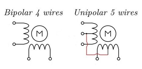
For a two-phase stepper motor, there are two winding arrangements of electromagnetic coils.
- Unipolar
- Bipolar
Unipolar Motor
- Only one winding with a center tap per phase.
- Each winding section is switched on for each direction of the magnetic field.
- The center tap of each winding is made common.
Bipolar Motor
- A single winding per phase.
- The current in the winding must be reversed to reverse a magnetic pole.
- There are two leads per phase; none are common.
Step Modes
In this article, we will use a unipolar stepper motor. Unipolar stepper motors can be used in three modes:
- Wave Drive mode
- Full Drive mode
- Half Drive mode
Wave Drive
- Only one electromagnet is energized at a time.
- The generation of torque will be lower than at full drive.
- This mode reduces power consumption.
- We choose this step mode when the low power consumption factor is more important than torque.
Full Drive
- Two electromagnets energize at the same time.
- The generation of torque will be greater than with wave drive.
- Power consumption is higher in this mode.
- We choose this step mode when torque is more important than power consumption.
Half Drive
- One and two electromagnets are alternately energized in this mode.
- It is a combination of both, wave drive and full drive.
- It has low torque, but the angular resolution is doubled.
- This type of drive is chosen when we want to increase the angular resolution of the motor.
Since each drive has its own advantages and disadvantages, we choose the drive according to the application we want and its power consumption.
Stepper Motor Interfacing with 8051 Microcontroller
Due to the high voltage and current limitations of the microcontroller, we use a motor Driver IC. We can use L293D or ULN2003. You can check our articles on these drivers for more details.
Circuit Components
- AT89C51 microcontroller
- 12 MHz Oscillator.
- 12V DC battery.
- 5V DC battery.
- L293D motor driver
- Unipolar Stepper motor – 1.
- 2 Ceramic capacitors – 33pF
- 300Ω resistors – 3
- Push buttons – 3
Connections
| Outputs | Inputs |
|---|---|
| 8051 MCU’s lower four pins as output of port 2 | Connects to input of L293D (motor driver IC) to drive one stepper motor |
| 3 buttons connect to manually, start and stop the motor | 8051 MCU’s lower three pins as inputs to port 0 |
| L293D Outputs (OUT1, OUT2, OUT3, and OUT4) | Inputs of stepper motor |
| 12 V battery | VS pin of motor |
| 5 V battery | VSS of motor driver’s IC |
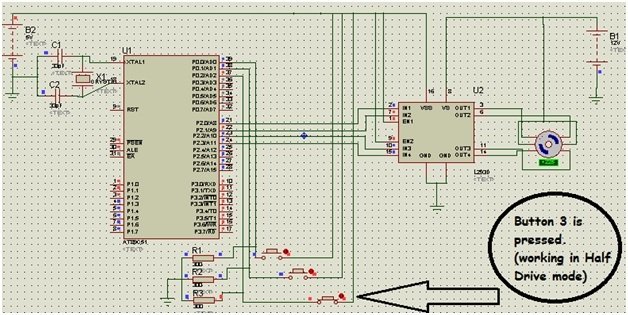
Proteus Schematic of Stepper Motor Interfacing with 8051 Microcontroller
In this section, we have provided the Proteus schematic we have used to perform simulation of stepper motor.
Working of Stepper Motor Interfacing with 8051 Microcontroller
As we discussed above, the stepper motor has three drive modes. In this section, we will configure and discuss the working of all the drive modes of the stepper motor.
Wave Drive mode
We tried to use all three modes. When we press button 1, it works as a wave drive. Only one electromagnet is energized at a time, and in coding, only one pin is high at a time. When we open the switch or button, the motor tends to stop within a few seconds.
| Wave drive Stepping Sequence | ||||
| Step # | Pin 1 | Pin 2 | Pin 3 | Pin4 |
| 1 | 1 | 0 | 0 | 0 |
| 2 | 0 | 1 | 0 | 0 |
| 3 | 0 | 0 | 1 | 0 |
| 4 | 0 | 0 | 0 | 1 |
Full Drive Mode
When we press button 2, it works as a full drive. Two electromagnets are energized at the same time, and in coding, one pin is high at a time. When we open the switch, or button 2, the motor tends to stop within a few seconds.
| Full-Drive Stepping Sequence | ||||
| Step # | Pin 1 | Pin 2 | Pin 3 | Pin4 |
| 1 | 1 | 1 | 0 | 0 |
| 2 | 0 | 1 | 1 | 0 |
| 3 | 0 | 0 | 1 | 1 |
| 4 | 1 | 0 | 0 | 1 |
Half Drive Mode
When we press button 3, it works as a half drive. In half-drive mode, one and two electromagnets energize alternately at a single time, and in coding:
- The first pin is high.
- Then first and second both get high.
- The second pin alone gets high.
- The second pin, along with the third, goes high.
- In the same way, alternatively, one and two pins go high.
| Half-Drive Stepping Sequence | ||||
| Step # | Pin 1 | Pin 2 | Pin 3 | Pin4 |
| 1 | 1 | 0 | 0 | 0 |
| 2 | 1 | 1 | 0 | 0 |
| 3 | 0 | 1 | 0 | 0 |
| 4 | 0 | 1 | 1 | 0 |
| 5 | 0 | 0 | 1 | 0 |
| 6 | 0 | 0 | 1 | 1 |
| 7 | 0 | 0 | 0 | 1 |
| 8 | 1 | 0 | 0 | 1 |
When we open the switch or button, the motor tends to stop within a few seconds.
Code of Stepper Motor Interfacing with 8051 Microcontroller
Here we have provided the code used in the Proteus simulation above.
#include<reg52.h>

void delay(int);

sbit B1 = P0 ^ 0; // Port 0, Pin 0
sbit B2 = P0 ^ 1; // Port 0, Pin 1
sbit B3 = P0 ^ 2; // Port 0, Pin 2

void main()
{
  P1 = 0x07;
  P2 = 0x00;

  if (B1 == 1) //for wave drive
  {
    P2 = 0x01; //0001
    delay(1000);

    P2 = 0x02; //0010
    delay(1000);

    P2 = 0x04; //0100
    delay(1000);

    P2 = 0x08; //1000
    delay(1000);
  }

  if (B1 == 0)
  {
    P2 = 00000000;
  }

  if (B2 == 1) //for full drive
  {
    P2 = 0x03; //0011
    delay(1000);

    P2 = 0x06; //0110
    delay(1000);

    P2 = 0x0C; //1100
    delay(1000);

    P2 = 0x09; //1001
    delay(1000);
  }

  if (B2 == 0)
  {
    P2 = 00000000;
  }

  if (B3 == 1) //for half drive
  {
    P2 = 0x01; //0001
    delay(1000);

    P2 = 0x03; //0011
    delay(1000);

    P2 = 0x02; //0010
    delay(1000);

    P2 = 0x06; //0110
    delay(1000);

    P2 = 0x04; //0100
    delay(1000);

    P2 = 0x0C; //1100
    delay(1000);

    P2 = 0x08; //1000
    delay(1000);

    P2 = 0x09; //1001
    delay(1000);
  }

  if (B3 == 0)
  {
    P2 = 00000000;
  }
}

void delay(int k)
{
  int i, j;

  for (i = 0; i < k; i++)
  {
    for (j = 0; j < 100; j++)
    {

    }
  }
}
Code Explanation
In this section, we will discuss the workings of the code.
#include<reg52.h>

void delay(int);

sbit B1 = P0 ^ 0; // Port 0, Pin 0
sbit B2 = P0 ^ 1; // Port 0, Pin 1
sbit B3 = P0 ^ 2; // Port 0, Pin 2
Firstly, we include the header tag to control the registers of the 8051 microcontroller. Then we declare the delay function. At last, we initialize Port 0’s lower pins as button pins.
void main()
{
  P1 = 0x07;
  P2 = 0x00;

  if (B1 == 1) //for wave drive
  {
    P2 = 0x01; //0001
    delay(1000);

    P2 = 0x02; //0010
    delay(1000);

    P2 = 0x04; //0100
    delay(1000);

    P2 = 0x08; //1000
    delay(1000);
  }

  if (B1 == 0)
  {
    P2 = 00000000;
  }
Then, in the void main function, we set ports 1 and 2. After this, we check the state of the button. If we press button 1, then the stepper motor will work in wave drive mode. We set the commands for moving each step with a delay of 1000. If button 1 is not pressed, the motor stops.
if (B2 == 1) //for full drive
  {
    P2 = 0x03; //0011
    delay(1000);

    P2 = 0x06; //0110
    delay(1000);

    P2 = 0x0C; //1100
    delay(1000);

    P2 = 0x09; //1001
    delay(1000);
  }

  if (B2 == 0)
  {
    P2 = 00000000;
  }
If we press button 2, the motor will work in full drive mode. Here we set the commands for the 4 steps of the stepper motor in full drive mode with a delay of 1000. As soon as we release the button, the motor stops due to the B2 == 0 condition.
if (B3 == 1) //for half drive
  {
    P2 = 0x01; //0001
    delay(1000);

    P2 = 0x03; //0011
    delay(1000);

    P2 = 0x02; //0010
    delay(1000);

    P2 = 0x06; //0110
    delay(1000);

    P2 = 0x04; //0100
    delay(1000);

    P2 = 0x0C; //1100
    delay(1000);

    P2 = 0x08; //1000
    delay(1000);

    P2 = 0x09; //1001
    delay(1000);
  }

  if (B3 == 0)
  {
    P2 = 00000000;
  }
}
Now if we press button 3, the motor will work in half-drive mode. We have set the commands for each step in half-drive mode. As soon as we release button 3, the stepper motor stops.
void delay(int k)
{
  int i, j;

  for (i = 0; i < k; i++)
  {
    for (j = 0; j < 100; j++)
    {

    }
  }
}
Lastly, we have the void delay function. Here we keep the microcontroller busy in loop iteration for an appropriate time to get a delay in the program.
Conclusion
In this article, we have discussed the following topics
- Comparison between stepper and DC motor.
- Basics of stepper motor.
- Step modes and interfacing with the 8051 microcontrollers.
- Proteus simulation
- Working of stepper motor
- Code and its explanation
Related Articles
You may also like to read:
- Stepper Motor Control with L293D Motor Driver IC and Arduino
- DC Motor Speed and Direction Control with L293D Driver IC and Arduino
- ESP8266 NodeMCU with Stepper Motor (28BYJ-48 and ULN2003 Motor Driver)
- ESP32 Interface with Stepper Motor (28BYJ-48 and ULN2003 Motor Driver)
- Stepper Motor Interfacing with TM4C123 Tiva Launchpad
This concludes our tutorial. If you have any queries or face any issues while following the tutorial, Let us know in the comment section below.
Bilal please replay to my mail.
Very urgent.
It is a widely used device that translate electrical pulse into mechanical movement. Most common stepper motor have 4 stator winding
I am using uln drivers to controll the stepper motor and I program the code using stepper motor, I connected the Arduino to load and it was not working good , I refered some sites and tried a lot many methods to interface with uln drivers using external but it was not working properly i am totally confused about that, can anyone provide me the solution please…!!!
i have an issue with how to:
1. Design the appropriate control via a microcontroller that enables a stepper motor of a syringe pump (as shown in Figure 1), to be able to administer fluid at the following volumes:
i. 5 ml/min
ii. 10 ml/min
iii. 15 ml/min
iv. 20 ml/min
2. Display the selected flow rate of (a) on an LCD panel and construct the overall setup for functionality test through Proteus. Your design should include 4 SPST switches for the selection of the flowrate.
May I need your help for this