This article will teach you how to interface a microcontroller with an optocoupler. How can you interface AVR, PIC, and 8051 microcontrollers with an optocoupler? What exactly is an optocoupler? What are the fundamental principles of an optocoupler? Power electronics projects, such as firing angle control circuits and AC power control circuits, often rely on optocouplers for various applications. Additionally, optocouplers find applications in communication-based projects as well as microcontroller-based projects. Microcontroller interfacing with an optocoupler, just like LED interfacing with a microcontroller, will be elaborated on in the latter part of this article.
Recommended Components
The following parts and reference books are useful for building and learning 8051 microcontroller projects.
| Component | How it’s used in your 8051 projects | Buy on Amazon |
|---|---|---|
| AT89S52 (8051) microcontroller | A modern, in-system-programmable 8051-core MCU that runs the code in these tutorials. | Check Price |
| USBasp programmer (ISP) | Burns the compiled HEX file into the AT89S51/AT89S52 over the ISP header. | Check Price |
| Breadboard | Solderless base for wiring the 8051 and the project’s components. | Check Price |
| Jumper Wires | Make the connections between the MCU, components and power rails. | Check Price |
| Book: The 8051 Microcontroller & Embedded Systems (Mazidi) | The classic 8051 textbook — architecture, assembly & C programming with interfacing examples. | Check Price |
| Book: The 8051 Microcontroller, 3rd Ed. (Ayala) | A popular reference covering 8051 architecture, programming and applications. | Check Price |
As an Amazon Associate we earn from qualifying purchases. Prices and availability are accurate as of the date/time indicated and are subject to change.
What is Optocoupler?
An optocoupler is also called an optoisolator, a photocoupler, and an optical isolator. It is used to provide isolation between two electrical circuits. This electrical component transmits input signals using light energy. It provides electrical coupling between the input and output through light waves. Its main purpose is to prevent changes in voltages at the output from affecting the input. Higher voltage fluctuations may damage components on the input side.
Optocoupler Working
An optocoupler consists of an LED that converts the input electrical signal into a light energy signal. A phototransistor at the output side detects the light signal and turns on when the LED light falls on it. In this way, its output becomes low and high according to the input signal, and the LED lights up as shown in the figure below:
Types of Optocouplers
Many types of optocouplers are available in the market according to their rating and design, such as fast optical isolators, analog optoisolators, and linear optocouplers. The rating depends on the output voltage drive capacity of the optoisolator. The most commonly used optoisolators for maximum output voltage are 30 volts, 70 volts, and 80 volts. You can purchase them from the market according to your requirements. They can easily operate within a temperature range of 70°C to 150°C. The names of the most commonly used optocouplers are given below:
So, there are many types of optocouplers available. It is impossible for me to show you how to interface all these optical isolators with microcontrollers. I will choose one and show you how to interface it with a microcontroller. The procedure for all the others will remain the same. For example, if you know how to interface an LCD with an AVR microcontroller, you can also easily interface it with a PIC, 8051, and ARM controller.
Applications of Optoisolator
In some applications, we use it to separate electronic circuits. For example, a DC motor produces back EMF with sudden changes in input voltage. Surge protectors are used to remove such effects. They are also widely used in communication devices like modems, etc.
In this article, we will show how to use the PC817 optocoupler because it is the most popular among engineering students and easily available in the market.
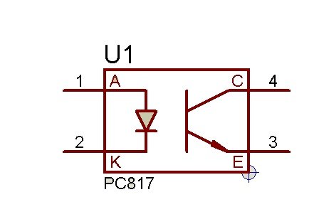
PC817 Optocoupler
PC817 is an optoisolator consists of an infrared diode and phototransistor. In electric circuits, we use mostly filters to remove noise. The circuit based on the capacitor and resistor always removes the noise from the incoming signal but the value capacitor and resistor always depend on the incoming signal. This circuit is only applicable where the incoming signal has some information or data but when we just need to forward the signal from one part of the circuit to the other part but signal contains noise, then we could use the combination of IR sender and receive.
In PC817 photoisolator IC circuit, the IR receives the noisy signal as a power from the one circuit and passes it to the other part through the IR signal. The other part receives the signal and then performs according to the circuit design.
PC817 Optocoupler Interfacing with PIC
The circuit diagram shown below illustrates how to interface a PC817 optocoupler with a PIC microcontroller:
The circuit consists of a 24V DC motor connected as a load. The PC817 optocoupler is used to provide isolation between the 5V and 24V circuits. Pin number RC5 of the PIC microcontroller’s port is used as the output pin to control the optocoupler.
The connections in the circuit are as follows:
- The cathode (longer terminal) of the PC817’s internal LED is connected to the PIC’s output pin.
- The anode (shorter terminal) of the LED is connected to the ground (GND) terminal.
- The collector terminal of the phototransistor is connected to the positive terminal of the 24V power supply.
- The emitter terminal of the phototransistor is connected to the negative terminal of the power supply and also the negative side of the load (DC motor).
In this setup, when the PIC’s output pin is HIGH, current flows through the optocoupler’s internal LED, causing it to emit light. The phototransistor detects this light and turns ON, allowing current to flow from the positive terminal of the power supply to the negative side of the load, thus activating the motor.
On the other hand, when the PIC’s output pin is LOW, no current flows through the optocoupler’s LED, and the phototransistor remains OFF. This breaks the circuit between the power supply and the motor, effectively turning it OFF.

Code
To control an optocoupler with a PIC microcontroller using MikroC for PIC, you’ll typically need to configure a digital output pin to control the optocoupler’s input LED.
The code for this project is written in the MIKROC compiler. If you do not know how to use MikroC for Pic, you can refer to these tutorials:
- How to Use “MikroC PRO for PIC” to Program PIC Microcontrollers
- Pic microcontroller programming in c using Mikroc Pro for PIC
Here’s an example code snippet that demonstrates how to control an optocoupler using MikroC for PIC:
// Define the pin that controls the optocoupler
sbit OptoControl at PORTC.B5; // Change to your desired pin

void main() {
    TRISC.B5 = 0; // Set the control pin as an output

    while (1) {
        // Turn on the optocoupler (LED) by setting the control pin high
        OptoControl = 1;

        // Wait for a desired period (you can adjust the delay as needed)
        Delay_ms(1000); // Delay for 1 second

        // Turn off the optocoupler by setting the control pin low
        OptoControl = 0;

        // Wait for another desired period
        Delay_ms(1000); // Delay for 1 second
    }
}
In this code, optocoupler control pin is connected to pin RC5 (you can change it to your desired pin) of PIC16F877A microcontroller. The code sets this pin as an output and then toggles it high and low at regular intervals to turn the optocoupler’s LED on and off. This, in turn, controls the state of the optocoupler’s output.
PC817 Optocoupler Interfacing with AVR
The circuit diagram shown below illustrates how to interface a PC817 optocoupler with a AVR microcontroller:

Code
To control an optocoupler connected to pin PD5 of an ATmega32 microcontroller using Atmel Studio, you can follow this example code. This code will toggle the state of PD5 (connected to the optocoupler input) at regular intervals to control the optocoupler:
#include <avr/io.h>
#include <util/delay.h>

#define OPTOCOUPLER_PIN PD5 // Define the pin for the optocoupler

int main(void) {
    // Set PD5 as an output
    DDRD |= (1 << OPTOCOUPLER_PIN);

    while (1) {
        // Turn on the optocoupler (set PD5 high)
        PORTD |= (1 << OPTOCOUPLER_PIN);

        // Delay for a desired period (you can adjust the delay as needed)
        _delay_ms(1000); // Delay for 1 second

        // Turn off the optocoupler (set PD5 low)
        PORTD &= ~(1 << OPTOCOUPLER_PIN);

        // Delay for another desired period
        _delay_ms(1000); // Delay for 1 second
    }

    return 0;
}
In this code:
- We define
OPTOCOUPLER_PINasPD5, which represents the pin connected to the optocoupler’s input. - We set
PD5as an output using theDDRDregister to control the optocoupler. - Inside the
whileloop, we toggle the state ofPD5high and low at regular intervals using thePORTDregister to control the optocoupler’s LED. - We use the
_delay_msfunction to create a delay between turning the optocoupler on and off (you can adjust the delay duration as needed).
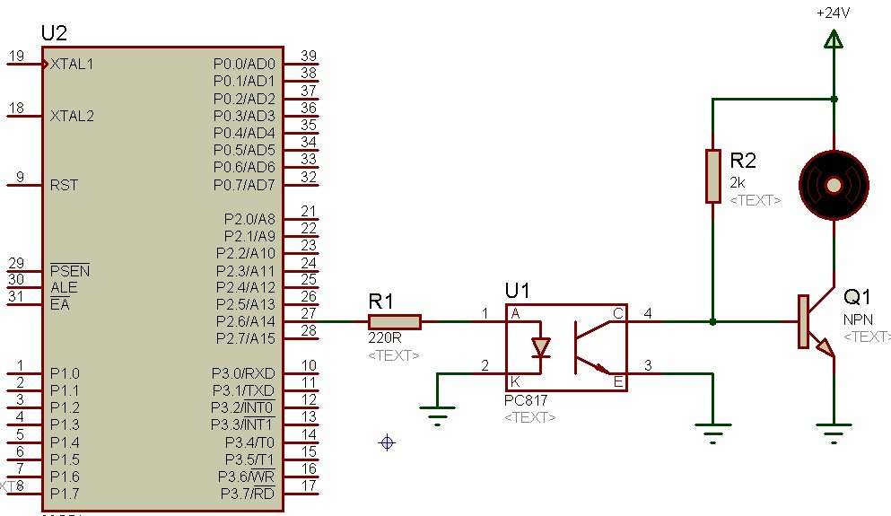
PC817 Optocoupler Interfacing with 8051
The circuit diagram shown below illustrates how to interface a PC817 optocoupler with a 8051 microcontroller:
Code
Below is an example Keil uVision code for an 8051 microcontroller to control an optocoupler connected to pin P2.6. This code will toggle the state of P2.6 to control the optocoupler:
#include <8051.h>

// Define the pin for the optocoupler
sbit OptoControl = P2^6;

void delay(unsigned int ms) {
    unsigned int i, j;
    for (i = 0; i < ms; i++) {
        for (j = 0; j < 112; j++);
    }
}

void main() {
    OptoControl = 0; // Initialize the optocoupler control pin as low

    while (1) {
        // Turn on the optocoupler (set P2.6 high)
        OptoControl = 1;

        // Delay for a desired period (you can adjust the delay as needed)
        delay(1000); // Delay for 1 second

        // Turn off the optocoupler (set P2.6 low)
        OptoControl = 0;

        // Delay for another desired period
        delay(1000); // Delay for 1 second
    }
}
In this code:
- We define
OptoControlasP2^6, which represents pin P2.6 connected to the optocoupler’s input. - Inside the
mainfunction, we initializeOptoControlas low (optocoupler off). - Inside the
whileloop, we toggle the state ofOptoControlhigh and low at regular intervals to control the optocoupler. - We use a
delayfunction to create a delay between turning the optocoupler on and off (you can adjust the delay duration as needed).
Conclusion
In conclusion, this article provided a comprehensive overview of optocouplers and their interface with microcontrollers. We learned that optocouplers serve as electrically isolated components that transmit input signals using light energy, preventing voltage fluctuations from affecting the input side. Various types of optocouplers were discussed, with the focus on the popular PC817 optocoupler. The article demonstrated how to interface the PC817 optocoupler with AVR, PIC, and 8051 microcontrollers, providing circuit diagrams and example codes for each. By following the instructions outlined in this article, readers can successfully incorporate optocouplers into their microcontroller-based projects, enabling them to achieve effective isolation and control in various applications.
Related content:
please send me the code for interfacing optocoupler with atmega 16
Is the 2nd and 3rd pin of the optocoupler connected to the same ground.? If they are connected to same ground, then how is this circuit isolated. You will have to use two different power supplies to provide proper isolation.
Salam,
Sir can i know. Does optocoupler have any relation in comunicate gsm and pic?? . There some article saying that optocoupler must be put between tx gsm to rx pic
I dont think so. Couplers are used to provide isolation in the circuit. There is no role of coupler while interfacing with GSM. But it also depend on your application. If you are talking about simple GSM interfacing with pic, then there is no requirement
resistors R1 and R2,how we can determine its values ??
Hi. I dont get something in avr – optoisolator scehem. + goes through from R2 and goes to base of transistor so base open the gate for C and E. So whts the act of optoisolator . I didnt get. Sorry
Can i get the code for it’s interfacing with pic16F877A
what is the technical differences between the normal switch and optocoupler?