6N137 is a single-channel high-speed optoisolator. Every optocoupler comes with a different feature to solve the requirement in every situation. An optocoupler name 6N137 is designed as one of the high-speed optocouplers. This optocoupler comes up with 10Mbit/sec speed which uses as optocoupler between two circuits for multiple purposes. IC 6N137 internally comes up IR transmitter but the receiver end comes up with an NMOS transistor which keeps it protected from leakage.
Getting Started 6N137
The recommended operating voltage for IC is 5V but at the output side, it does not support the switching of high load which makes it suitable only for LOW voltage devices. It also comes up with an enable pin which makes it handy for using in-circuit of flash for the camera. Optocoupler can work with both AC and DC but using it with any circuit a 0.1uF capacitor is recommended. So, in those cases where high-speed optocoupler is needed the IC will be a perfect device to remove the noise and data conversion.
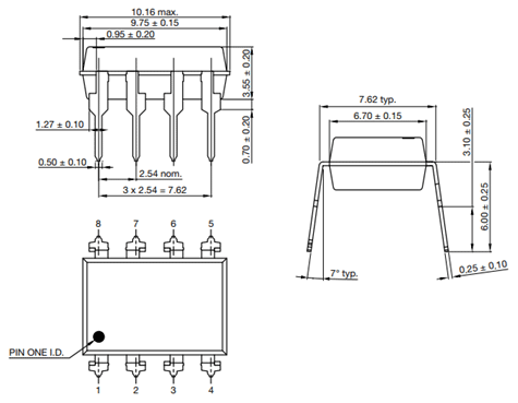
Pin Configuration Details 6N137
The pinout diagram of 6N137 is shown here and details of all pins are listed in the table.

| INPUT | ||
|---|---|---|
| NC | Pin 1 | Pin 1 is a no connection pin, which has no connection with the internal circuit and no usage with external circuit too. |
| ANODE | Pin 2 | Pin 2 is an anode pin used to give the logic input to the IR of the IC, to send the input data through IR transmission. |
| CATHODE | Pin 3 | Pin 3 is a cathode pin of the IR transmitter, mostly used as a common ground with sender circuit. |
| NC | Pin 4 | Pin 4 is also a no connection pin. |
| OUTPUT | ||
| GROUND | Pin 5 | Pin 5 is a ground pin for IR receiver within the optocoupler. |
| V0 | Pin 6 | Pin 6 is a logical output pin of 6N137 IC. |
| VE | Pin 7 | Pin 7 is the enable pin, which works with the output. The enable pin will be enabled by default. |
| Vcc | Pin 8 | Pin 8 is used to powerup the IC. |
Alternative options
Equivalent Optoisolators
VO2601, VO2611, VO2630, VO2631, VO4661
How and Where to use 6N137
The optocoupler 6N137 is one of the high speeds optocouplers due to its fast IR transmitter and receiver. The output is decided on the base of input and an enable pin. IR receiver output and enable pin both are connected to the NAND gate which helps to decide the output. To use the optocoupler there is some requirement for every circuit. Due to its dual capability of using both current AC and DC current, it should be connected with 0.1uF bypass capacitor with the power supply to avoid decoupling between both ends.
Then the input single should have the 5ns rise and fall time to get the response from the IC. It also should have an impedance of about 50ohm. The output pin of the IC contains an NMOS transistor which acts as a switch. The transistor can absorb the current or it can store the current too but to avoid storage for further output error a pull-up resistor will be used to avoid it. The value of the pull-up resistor is 330 to 4k which van avoid the floating error when the load will be connected at the output. The input signal of the in the IC can be probed but only when it necessary otherwise it won’t be necessary. The pull up resistor value will be different according to its requirement.

There is another pin on the IC know as enable pin, are most of the cases the enable pin gives the power on and off the ability to control devices. Here enables pin will be used to deliver the different outputs. The default state of enabling pin is HIGH. Even when there is no connection it will affect the output due to its default state, but it can be changed by proving logical signals.
6N137 Truth Table
The enable pin value and the input signals combination gives the output state which can be considered according to the following truth table:
| TRUTH TABLE | ||
| LED INPUT | ENABLE | OUTPUT |
|---|---|---|
| 0 | 0 | 1 |
| 1 | 0 | 1 |
| 0 | 1 | 1 |
| 1 | 1 | 0 |
| 0 | X | 0 |
| 1 | X | 1 |
Timing Diagram
In high-speed devices the propagation delay should be understood properly otherwise it could affect the output very badly. In 6N137 the output could be affected by propagation delay easily which is 5ns. In the above truth table as you see some LOW and HIGH states for output. This will only happen after 50ns change in logic state. Each output state will change after 50ns change in logic input no matter which input state optocoupler is receiving. Here the graphical representation of propagation delay:

6N137 Examples
In the example of 6N137 optocoupler, we will design a module that is used for isolation between two circuits. The module is basically knowing as isolation module but due to its high speed, it is also known as HIGH-SPEED ISOLATION METHOD. In Isolation, the circuit communicates between two devices without any delay and it protects the circuit with low voltage from the high voltages. To design an isolation circuit of a 3 to 5-volt circuit we will use some resistances and other devices will be according to the optocoupler requirement. The circuit diagram is given below:
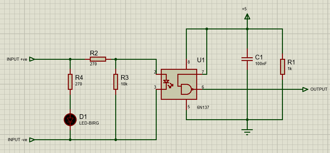
The above circuit will be designed with an LED just to detect the signal transferring and the resistances will be used to limit the voltages. Whenever the data will start transfer there won’t be any communication between each circuit. In case of output become shorted the input circuit will become open without affecting it. Other optocouplers can be used for the same functions but in communication like Fibre optics or data communication or conversion the data needs to be travel faster and the 6N137 isolation module gives the ability to make the isolation between two devices to communicate without worrying about data noise and circuit safety.
Features 6N137
These details on Features, Electrical characteristics and Applications are according to the datasheet.
- 6N137 comes up with 10Mbit/sec speed, which makes it one of the high speeds optocoupler.
- It has the capability of 5Volt CMOS.
- Low voltage AC and DC can be applied directly to the output and input. Its performance will be measured according to temperate on both currents.
- IC comes with 5mA current operating capacity.
- The output of optocoupler always comes in logic state, HIGH and LOW.
- 6N137 is a choice of CMR because of its high common-mode transient immunity.
- Due to availability of IC in multiple packages as DIP and SMD, it can be used with any circuit.
- Its output is based not only input, but it also has an effect by a third pin which comes in handy during using the IC with camera flash.
- The receiver end has an NMOS transistor which saves it from the leakage.
SPECIFICATIONS
- The maximum power supply input for IC is 7V but typical power input is 5V.
- The minimum input voltage for the HIGH state is 2V and for maximum input for the LOW state is 0.8V.
- IC gives the propagation delay of 50ns approximately.
- The operating temperature for IC is -40 to 100 and its storage temperature range is -55 to 150.
- The Solder temperature range for reflow soldering and lead soldering is 260, above this optocoupler performance will be affected.
- Power dissipation for IC is 85mW.
- The external output pull-up resistor range is 330 to 4k.
Applications 6N137
- Microprocessor Systems and computer peripheral interface use optocoupler.
- IC uses noise eliminations, data transmission, analog to digital and digital to analog conversion.
- The digital control power supply also controls the power using 6N137.
- Optocoupler 6N137 is used is strode lights of cameras.
- Fiber optics communications also used high-speed optocoupler for communication.
2D Diagram
I need help where to downloaf a sg 3525 pwm ic to use in proteus for simulation.
Nice explanation. Thank you!
How can I get that ic in Uganda?