PC817 is an optoisolator consists of an infrared diode and phototransistor. In electric circuits, we use mostly filters to remove noise. The circuit based on the capacitor and resistor always removes the noise from the incoming signal but the value capacitor and resistor always depend on the incoming signal. This circuit is only applicable where the incoming signal has some information or data but when we just need to forward the signal from one part of the circuit to the other part but signal contains noise, then we could use the combination of IR sender and receive.
In PC817 photoisolator IC circuit, the IR receives the noisy signal as a power from the one circuit and passes it to the other part through the IR signal. The other part receives the signal and then performs according to the circuit design.
Recommended Components
The following parts are used in this article, along with a generic electronics kit that is handy for building and testing the circuit.
| Component | How it’s used | Buy on Amazon |
|---|---|---|
| PC817 optocoupler | The PC817 phototransistor optocoupler this article covers. | Check Price |
| Electronic component assortment kit (1390 pcs) | A handy assortment of resistors, capacitors, LEDs, diodes and transistors for building circuits. | Check Price |
| Digital multimeter (AstroAI) | Measures voltage, current, resistance and checks continuity while you build and debug. | Check Price |
| Breadboard | Solderless base for prototyping the circuit. | Check Price |
| Jumper Wires | Make the connections on the breadboard. | Check Price |
As an Amazon Associate we earn from qualifying purchases. Prices and availability are accurate as of the date/time indicated and are subject to change.
PC817 Optocoupler Introduction
PC817 consists of an LED emitting diode and phototransistor. They are coupled together optically. The Electrical signal transfers between an input and an output side optically without any physical connection between both sides. The IR circuit can be designed by hand but we have a fully predesigned and small size integrated circuit IC knows as PC817 Optocoupler. The PC817 Optocoupler is small in size and comes in multiple packages.
It can be directly connected to any low voltage dc device or microcontroller. The input voltages will have the same effect from every side on the optocoupler, it will just transfer the signal to the receiver and then the receiver will give the logic signal as output. The optocoupler has many uses due to its small and compact size as a control operation.
PC817 Pinout Diagram
The diagram represents the pin configuration diagram and explains the functionality of each pin. In this pinout diagram of PC817, pin1 and pin2 are parts of the input side and pin3 – pin4 are output pins.

| INPUT | ||
|---|---|---|
| ANODE | PIN 1 | Pin 1 is an anode pin of IR input within the Optocoupler. It will give the logical input signal to the internal IR. |
| CATHODE | PIN 2 | Pin 2 is the cathode pin of the IR within the optocoupler. It will give the IR to make the common ground with the circuit and Power supply. |
| OUTPUT | ||
| COLLECTOR | PIN 3 | Pin 3 is an output pin of the internal IR receiver of the optocoupler. It will give the logical output by receiving the IR signal. |
| EMITTER | PIN 4 | Pin 4 is a ground pin for IR receiver. It will be used to make the common ground with Power supply and the circuit. |
Alternative Optoisolator
These are the alternative options: 4N25, 6N136, MOC3021, MOC3041, 6N137
PC817 IC Equivalent
PC817A, PC817B, PC817C, PC817D
How PC817 Works?
The working of PC817 is very simple but to use it with different devices comes with specifications. The optocoupler at input requires current limiting one resistance but at the output, we will need to connect the logic output pin with the power pin. Whenever the IR signal will be generated at then the logic state will be changed from 1 to 0, due to change in the flow of current.
Circuit Diagram
The circuit design is given below.
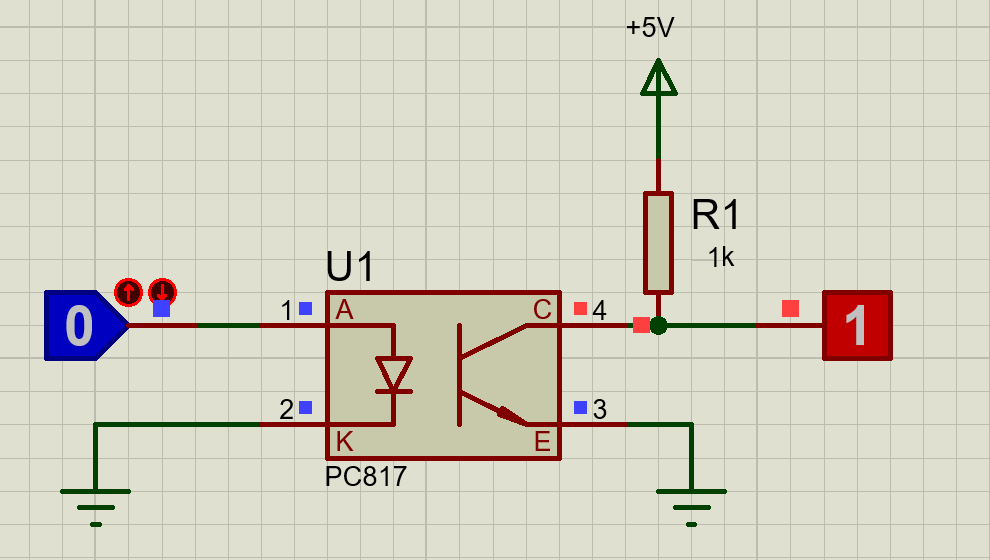
The circuit is totally simple but the resistance will give it protection at the input in HIGH voltages. The Optocoupler is just a small-sized circuit of infrared receiver and sender but in case of making it with externally by using IR sender and receiver cause many problems.
- First manually made circuit comes in a larger size, then in case of IR receiving devices the circuit IR sender of auto coupler or receiver could be affected by other IR signals.
- The closed communication protects it from many things especially from temperature too.
- The manually made Optocoupler has low voltage operating voltage level as compare to this PC817.
PC817 Examples
The optocoupler has many uses but due to increasing in IOT field from 2012 the optocoupler is now increasingly using in daily life to control the appliances. In IoT especially home automation or heavy load control, we need to control the AC load by the effect of change in frequency. To do so we will need a zero cross. The zero-cross is the method in which we receive the change in the frequency signal of the AC voltages. The change in voltage gives the ability to control the AC. The AC load is further control by some TRIACS.
The basic features of optocoupler here is to give the change in frequency pulse. The optocoupler is connected to a rectifier through a HIGH watt resistance and the rectifier is converting the HIGH AC to HIGH DC and resistance is lowering down the DC voltages. The DC voltages coming out from the resistance is lower in voltages but it has a noise that is not effective to use as the signal. To convert it to the proper signal we use the optocoupler. The optocoupler generates the same type of single pulse no matter how much the signal has noise. This single pulse is used to detect the events of change in frequency which is known as zero crosses. This zero-cross allows the microcontrollers to control the HIGH ac load with the simple microcontroller.
220V AC Light Dimmer Example with PC817
To use the dimmer we will need to use the microcontroller. Here we will describe a method to control the dimmer with an Arduino.
Interfacing with Arduino
Here’s the circuit:

The zero cross-pin will be used at interrupt pin and any digital pins can be used to control the signal. Here’s in the image we describe the pins for IR and dimmer but these pins are not specific. To control the dimmer with the Arduino the following code will be used:
Arduino Sketch
#include <TimerOne.h>
volatile int i = 0;                               // Variable to use as a counter
volatile boolean zero_cross = 0;   // Boolean to store a "switch" to tell us if we have crossed zero
int AC_pin = 3;                                               // Output to Opto Triac
int dim = 128;                                              // Dimming level (0-128)  0 = on, 128 = 0ff
int freqStep = 77;                                    // This is the delay-per-brightness step in microseconds.
int a = 0;
int pin = 13;
int data = 0;
void setup()
{
Serial.begin(9600);
pinMode(AC_pin, OUTPUT);                              // Set the Triac pin as output
attachInterrupt(0, zero_cross_detect, RISING);    // Attach an Interupt to Pin 2 (interupt 0) for Zero Cross Detection

Timer1.initialize(freqStep);                                   // Initialize TimerOne library for the freq we need

Timer1.attachInterrupt(dim_check2, freqStep);

}

void zero_cross_detect()

{

zero_cross = true;               // set the boolean to true to tell our dimming function that a zero cross has occured

i = 0;

digitalWrite(AC_pin, LOW);

}

// Turn on the TRIAC at the appropriate time

void dim_check2()

{

if (zero_cross == true) {

if (i >= dim) {

digitalWrite(AC_pin, HIGH);    // turn on light

i = 0;                                                        // reset time step counter

zero_cross = false;                                // reset zero cross detection

}

else {

i++;                                                 // increment time step counter

}

}

}

void loop() {

if (Serial.available()) {
a++;
if (a == 1) data = Serial.read();
if (a == 2)
 {
pin = Serial.read();
a = 0;
dim = data;
}
}
}
The above code describes how the zero-cross can be used with the Arduino and how Arduino could control the high voltages. The code is just for one dimmer to make it for multiple dimmers the code will require some modifications.
Proteus Simulation
PC817 optocoupler Features
- It comes with 4-pins in two packages, DIP and SMT.
- The device has an internal protection form of electrical isolation. The protection is for both input and output. It can protect up to HIGH 5KV from electric isolation.
- The optocoupler can be used with an external resistor with high voltage devices to operate with low voltage devices.
- The optocoupler can operate with any kind of device with internal interfaces like with TTL device, Microcontrollers and even with HIGH DC voltage with some internal resistors.
- Optocoupler PC817 comes with internal protection from reverse current. Due to the one-way current flow nature of IR, the PC817 protects the IR from any reverse current.
SPECIFICATIONS
- The voltage ratio at the emitter and collector will be a maximum of 80V.
- The maximum current ratio at the collector will be 50mA
- The cut-off frequency for optocoupler will be 80kHz.
- Optocoupler also comes with rising and fall time. The rise and fall time are 18us.
- The maximum operating temperature for optocoupler is -30 to 100 degrees.
- During soldering, the temperature range for optocoupler is 260 degrees. The increase in temperature during soldering could damage the optocoupler.
- The optocoupler comes with an internal storage temperature of about -55 -125 degrees.
- Power Dissipation of the IC is 200mW.
- The internal resistance of the optocoupler is 100 ohms.
PC817 Applications
- In protection like electric isolation, PC 817 is reliable to use due to its functionality.
- PC817 is much efficient in switching for microcontrollers. Simple transistors can be used but due to its neglecting the noise factor the optocoupler can be used as switching too.
- In signal Isolation, the optocoupler is faster and widely used from the previous century.
- Optocoupler is also used for a basic noise coupling circuit to keep the circuit in use without any disconnectivity.
- Nowadays IC has the best uses in IoT devices for switching and zero cross. In-Home appliance to control AC load optocoupler gives the pulse of change in frequency which gives the ability to control the AC load at a specific range.
- For Signal transmission the optocoupler is widely used nowadays.
2D dimension

what does the void loop do? are we to input a dim value from the serial monitor? thank you.
void loop() {
if (Serial.available()) {
a++;
if (a == 1) data = Serial.read();
if (a == 2) {
pin = Serial.read();
a = 0;
dim = data;
}
}
}
To keep the device running.
void dim_check2() what is this function doing?
OUTPUT
COLLECTOR PIN 3 Pin 3 is an output pin of the internal IR receiver of the optocoupler. It will give the logical output by receiving the IR signal.
EMITTER PIN 4 Pin 4 is a ground pin for IR receiver. It will be used to make the common ground with Power supply and the circuit.
Small error in the beginning of this article, right numeration is:
Emitter – pin 3, collector – pin 4
PC 817 diagram error in statement below the diagram. Switch around collector and emitter statements. Emitter is ground, not collector.
Good article, but the schematic for the TRIAC and zero crossing, is missing any current limiting resistor for the optocoupler LED.
For the input of PC817 also, and it is 220 VAC * sqrt(2) = 311 VDC, the resitor is missing. 💀