In this article, we will learn to interface an analog-to-digital converter (ADC 0804) with an 8051 microcontroller. Unlike the PIC, Arduino, and AVR microcontrollers, the 8051 microcontroller does not have a built-in ADC. If we want to interface any sensor with the 8051 microcontroller which provides analog output, we have to use an external ADC. An analog signal can be the output of any sensor. The ADC converts this output data to digital format, and the microcontroller can use this data for further processing.
Let’s look at an example to understand the use of the external ADC 0804. In the case where we want to measure temperature with an 8051 microcontroller and we are using an LM35 temperature sensor to measure the temperature, this sensor gives output in the form of an analog voltage. We need to convert analog values to digital so the 8051 microcontroller can communicate with the LM35 temperature sensor. For this, we use an external analog-to-digital converter (ADC), which converts the analog signal into digital format, and the 8051 can process this data.
ADC0804 Introduction
ADC0804 is an 8-bit analog to digital converter IC which can measure up to 8 analog input simultaneously. That means the digital output value can vary between 0 to 255. It uses a successive approximation converter which is based on the differential potentiometric ladder.
Every device cannot perform each and every operation. There are always different devices that can perform different operations and convert them for other devices to perform another’s function. The basic problem we face is the translation of data between these devices.
In Electronics Most of the time, different methods of communication between different devices were invented so different devices could perform efficiently with two or multiple different objects and devices.
Why Do We Need to Use ADC?
When it comes to real life, or we can say in the time domain, the output of different events can always be represented in mathematical form or mathematical values. These mathematical values are always in continuous form. In other words, we can say that these values always have a starting and ending point, but between these two points, they have infinite values.
These analog values are easy to read in the time domain (real life). However, when it comes to machines or electronic devices, most of them are unable to read them properly. They could read their starting or maybe ending point, but in most cases, they are unable to read them accurately. Machines and electronic devices always perform their operations in the “frequency domain.” To solve these kinds of issues, we usually use Analog to Digital Converters (ADC).
Features of ADC0804
The ADC 0804 is an external analog-to-digital converter, its main features are as follows:
- 8-bit resolution
- Differential analogue voltage inputs
- 0–5V input voltage range
- No zero adjustment
- Built-in clock generator
- The voltage at Vref/2 (pin 9) can be externally adjusted to convert smaller input voltage spans to full 8-bit resolution.
Resolution
Resolution refers to the conversion of an analog voltage to a digital value. It indicates the number of discrete values that an ADC can produce over the range of analog values. The values are usually stored electronically in binary form, so the resolution is usually expressed in bits.
Step Size
It is the voltage difference between two digital levels or values that the ADC can measure. In a 4-bit converter, an input of 1 Volt produces an output of 0001, so the step size is 1 Volt. We always consider 0 volts as 0000. By decreasing the step size to 0.5 V, we can reduce the distortion of the signal, but it lowers the maximum input reading. If we are using a smaller step size, we need a higher-bit converter to have maximum voltage.
ADC 0804 is a single-channel analog-to-digital converter. It takes only one analog signal and has an 8-bit resolution. Other ADCs can have an n-bit resolution, with n being 8, 10, 12, 16, or 24 bits. If the ADC has a higher resolution, it provides smaller step sizes. For an ADC with an 8-bit resolution, the input voltage span is between 0V – 5V, and the step size is 19.53 mV (5V/255). In this situation, we refer to Vref/2 as being left open.
Pinout of ADC 0804

Pin Description
Pin description of ADC 0804 is as follows:
| AD 0804 pin | Function |
|---|---|
| CS – Chip Select | It is an active low pin used to activate ADC 0804. |
| RD – Read | This is an active low-input pin. ADC 0804 stores the result in an internal register after the conversion of analog data. This pin helps get the data out of the ADC 0804. When CS = 0, a high-to-low pulse is given to the RD pin, and then digital output comes on the pins D0-D7. |
| WR – Write | It is an active low input pin that is used to initiate the ADC to start the conversion process. When CS = 0, WR makes a low-to-high transition, and then ADC starts the conversion process. |
| CLK IN – Clock In | This is an input pin that is connected to an external clock source. |
| INTR – Interrupt | This is an output pin and is active low. When the conversion is over, this pin goes low. |
| Vin+ | The analog input to the ADC. |
| Vin- | The analog input is connected to ground. |
| AGND – Analog Ground | Connected to the ground. |
| Vref/2 | Used to set the reference voltage. The default reference voltage is 5 volts when not connected. The step size can be reduced by using this pin. |
| DGND | Connected to the ground. |
| D7 – D0 | Output bits of binary data. |
| CLKR | To reset the clock. |
| VCC | Power supply of ADC. |
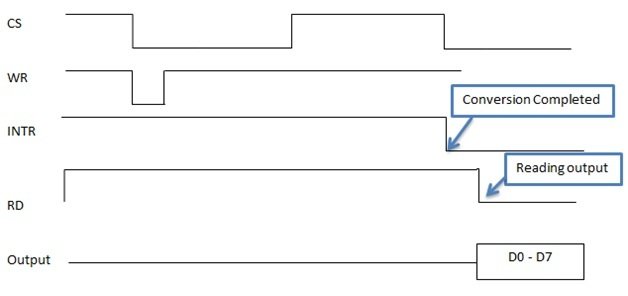
Conversion Steps
- Firstly, make CS = 0.
- Send a low-to-high pulse to the WR pin to start the conversion.
- Keep checking the INTR pin.
- INTR = 1, if conversion is not finished, poll until it is finished.
- INTR = 0, if the conversion is finished.
- If conversion is finished (INTR=0), Ensure CS = 0
- Then, send a high-to-low pulse to the RD pin to read the data from the ADC.
- If we connect the CS of the ADC to ground, then there will be no need to make or ensure it is zero.
You can learn more about ADC0804 here:
ADC 0804 Connection to 8051 Microcontroller
As we know, the microcontroller will provide control signals to the ADC. Its main connections are as follows:
| ADC 0804 Pins | 8051 MCU Pins |
|---|---|
| CS pin | GND |
| WR | 5 |
| RD | 6 |
| INTR | 4 |
| Data Out | PORT 0 |
- The demonstration of the output is through the LEDs. We connect these LEDs between the data-out pins of the ADC0804 and port 0 of the 8051 microcontroller.
- The input voltage from the preset is varied, and the output of the ADC also varies.
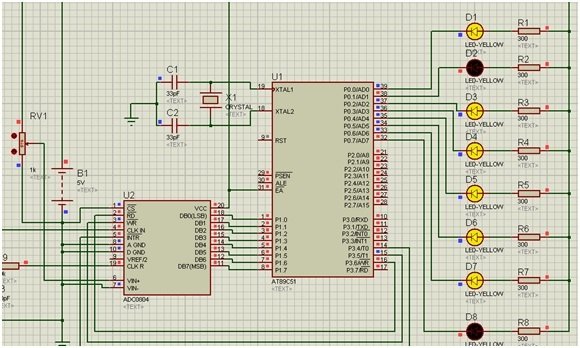
Proteus Schematic
In this section, we have provided the Proteus Schematic that we used for simulation. We have also attached the cases below.
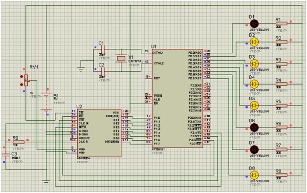
Simulation Explanation
In this schematic, we use Port 1 as the input port and port 0 as the output port. The voltage adjustment is done via a potentiometer. If the analog input voltage is 5 volts, then all LEDs will glow, indicating 11111111 in the binary format, which is the equivalent of 255 in the decimal format. If the voltage is zero, no LED will glow, indicating 00000000 in binary, which is equivalent to 0 in decimal.
Full Voltage
When full voltage given: In this case, we set the potentiometer to a minimum resistance, which means ADC 0804 receives full voltage, resulting in lighting up all the LEDs. We can represent this output as Output = 11111111 in the binary format.

Half Voltage
When half voltage is given: The potentiometer is set to half its resistance, which means we are providing roughly 2.5 volts to the ADC 0804. This results in 2 out of 8 LEDs turning off.
Zero Voltage
When zero voltage is given: In this case, we set the potentiometer to the maximum resistance. This results in the minimum voltage reaching ADC 0804. As this turns all the LEDs off, we can represent this output state as Output = 00000000 in the binary format.

8051 ADC0804 Code
Here we have provided the sketch we used in the Proteus simulation above.
#include<reg51.h>

#define input P1 //Input port (read values of ADC)
#define output P0 // Output port (connected to LED's)

void delay(unsigned intmsec);

voidadc();

sbitwr = P3 ^ 5; // Write pin.
sbitrd = P3 ^ 6; // Read pin.
sbitintr = P3 ^ 4; // Interrupt pin.

void main()
{
  input = 0xff; // Declare port 1 as input port.
  output = 0x00; // Declare port 0 as output port.

  while (1)
  {
    adc();
  }
}

void delay(unsigned intmsec) // Delay function
{
  int i, j;

  for (i = 0; i < msec; i++){
    for (j = 0; j < 1275; j++){

    }
  }
}

voidadc() // Reading values from ADC and display on the LED's
{
  rd = 1;
  wr = 0;

  delay(10);

  wr = 1;

  while (intr == 1);

  rd = 0;

  output = input;

  delay(10);

  intr = 1;
}
Code Explanation
In this section, we will discuss how the code works.
#include<reg51.h>

#define input P1 //Input port (read values of ADC)
#define output P0 // Output port (connected to LED's)
Firstly, we include the header file for controlling the register of the 8051 microcontroller using #include <reg51>. Then we define constants for Port 1 and Port 0.
void delay(unsigned intmsec);

void adc();

sbitwr = P3 ^ 5; // Write pin.
sbitrd = P3 ^ 6; // Read pin.
sbitintr = P3 ^ 4; // Interrupt pin.
Next, we declare two functions: delay and adc. We will discuss these in detail below; after this, we set the Port 3 pins 5, 6, and 4 for write, read, and interrupt, respectively. This will help us interface 8051 with ADC 0804.
void main()
{
  input = 0xff; // Declare port 1 as input port.
  output = 0x00; // Declare port 0 as output port.

  while (1)
  {
    adc();
  }
}
Now, we initialize Port 1 as input and Port 0 as output. In the while loop, we call the adc() function.
void delay(unsigned intmsec) // Delay function
{
  int i, j;

  for (i = 0; i < msec; i++){
    for (j = 0; j < 1275; j++){

    }
  }
}
We move to the void delay function, which has an argument of an unsigned integer. In the body of this function, we declare two variables, and we use these variables in the “for loop” to provide delay. These for loops will keep the microcontroller busy for the msec set as an argument.
voidadc() // Reading values from ADC and display on the LED's
{
  rd = 1;
  wr = 0;

  delay(10);

  wr = 1;

  while (intr == 1);

  rd = 0;

  output = input;

  delay(10);

  intr = 1;
}
Lastly, we move towards the void adc() function definition. In this function, we read the values from the ADC 0804. We set the read pin to high, which means that the microcontroller wants to read ADC 0804 data. After a delay of 10 msec, we set the write pin high as well. The interrupt condition in the while loop checks whether the ADC 0804 has converted an analog value to digital or not. Once it converts the value, we set the read pin to low and shift the analog value stored in input to output. Lastly, we set the intr pin to high with a delay of 10 msec for the next reading.
Conclusion
Here we have summarized the topics we have covered in this tutorial.
- ADC 0804, its uses, and its features.
- Pinout and pin description.
- ADC 0804 and 8051 MCU connections
- Proteus Schematic.
- Sketch and explanation.
Related articles:
If you liked reading this article, we have attached similar articles in the links below:
- ADC0804 ADC Introduction, Pinout, Features, and Examples.
- Tracking Type ADC -Up/Down Counter Analog to Digital Converter.
- Counter Type ADC – Staircase Approximation Analog to Digital Converter.
- PIC Microcontroller ADC – How to Use PIC18F4550 ADC.
- STM32 Blue Pill ADC with Polling, Interrupt, and DMA.
- Raspberry Pi Pico ADC with Voltage Measurement Examples.
- ESP32 ADC with Arduino IDE – Measuring voltage example.
This is all for this article; if you face any difficulty or issue, let us know in the comment section below.
In 8051 microcontroller, BCD to hexa decimal can be inbuilt or not
Please give the assembly language code