In the last tutorial, we learned about counter-type ADCs, which are single slope ADCs with an incrementing slope. Further, the counter value only increments until it matches the analog input voltage value. In simple words, the counter resets to zero after every single conversion. The counter counts only upward. Hence, it has only a positive slope, and in other directions, the slope is simply zero. In order to resolve this issue, we can use a tracking type ADC.
Tracking Type ADC Introduction
A tracking type ADC is an improved version of a counter type analog-to-digital converter. The counter type analog-to-digital converter has the drawback that it resets itself for every new conversion. It starts its count again from zero onward for every other conversion. Even a small change in the input voltage leads to the device being reset. Therefore, to cater to this issue, another type of analog-to-digital converter based on a similar schematic as a counter type analog-to-digital converter was introduced, which is known as a tracking type analog-to-digital converter. This post is an overview of the tracking type analog to digital converter, its workings, applications, advantages, and disadvantages.
Tracking Type ADC Schematic Diagram
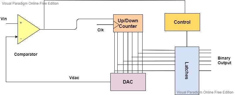
The schematic diagram of the tracking type analog-to-digital converter and counter type is alike except for the counter. The tracking type analog-to-digital converter consists of a comparator, a control circuit, an up-down counter, a digital-to-analog converter, and an output latch circuit that gives out the final binary outputs.

Tracking Type ADC Working
The comparator receives two voltages, i.e., the input voltage and the reference voltage. The input analog voltage is applied to the non-inverting end of the comparator, whereas the reference voltage is applied to the negative, or inverting, end of the comparator. This reference voltage is basically the output of the digital-to-analog converter that gets compared with the given input voltage and determines the state of the comparator.
If Vin > Vdac
When the respective analog-to-digital converter powers on, the output of the digital-to-analog converter is zero. When this is compared with the applied voltage, the comparator gets high, and the counter starts counting from zero onward. It means that it starts counting in the upward direction. In return, the output of the digital-to-analog converter starts to increase slowly.
If Vin < Vdac
But when the continuous input voltage is less than the output of the digital-to-analog converter, the comparator goes from a high to a low state at that particular time. This enables the up-down counter to start counting in the reverse direction, which is in the down direction, instead of resetting itself, just like the counter type ADC.
Once again, when the output of the digital to analog converter becomes greater than the input voltage, the comparator becomes high and the counter enters up-count mode, and vice versa, the counter enters down-count mode. The condition for whether the counter counts in an upward or downward direction depends on the input voltage, and the process keeps on repeating.
This analog-to-digital converter keeps track of the input voltage consistently for its functionality; therefore, it is called a tracking type analog-to-digital converter.
Output Latching
The output of the counter latches whenever the comparator transits its output. It means that every time the output of the comparator transitions from high to low or low to high, the binary output of the up-down counter is latched.
Conversion Time
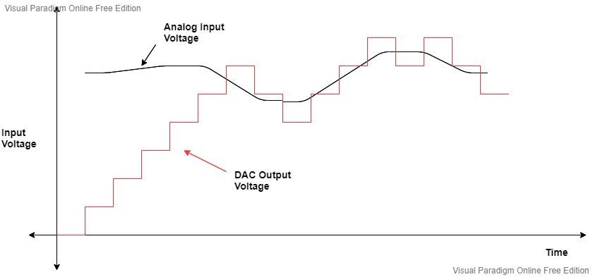
Here is the visual pattern of the output of the digital-to-analog converter:

The graph shows that in the beginning, the output of the digital-to-analog converter increases gradually until it reaches and tracks the input voltage.
The maximum conversion time at this point is:
Tc (max) = (2^N – 1) Tclk
Where N is the number of bits in the analog-to-digital converter and Tclk is the duration of the clock pulse.
This depicts that when the change in the input voltage becomes equal to the full-scale voltage of the digital-to-analog converter, the up-down counter moves from all zeros to all ones (0000—->1111) and from all ones to all zeros (1111—->0000).
The conversion time of the tracking type analog-to-digital converter depends on the changes in the input signal. If the input voltage changes rapidly, the conversion time will be longer, while it will be shorter if the input changes gradually. Refer to the figure below:

If we compare the average conversion time of counter type ADCs with tracking type ADCs, then the latter has a lower conversion time.
Sampling Time
The conversion time plays an important role in determining the sampling time of the analog-to-digital converter. It is the time after which the circuit samples the input signal. Generally, the sample time of an analog-to-digital converter is equal to the sum of the conversion time and the additional time delay.
Ts = Tc + Tdelay
Where Tdelay is the acquisition time and ADC component delay.
In order to sample the applied input signal at uniform intervals, the uniform sampling time needs to be equal to the maximum conversion time if the additional time delay is not considered.
Ts = Tc (max)
Sampling Frequency
It is the number of samples per second taken from a continuous analog signal to form discrete signals.
The sampling frequency is equal to the inverse of the sampling time.
fs = 1 / Tc (max)
If fs is the sampling frequency, then the maximum input frequency is:
fmax = fs/2
fmax = 1/(2*Tc(max))
The maximum frequency is obtained through the Nyquist theorem, which states that the sampling frequency should be twice the maximum input frequency.
The general equation shows that the maximum frequency is inversely proportional to the maximum conversion time if the additional delay is not considered. This result should be kept in mind while designing this analog-to-digital converter.
Advantages
- It is faster than the counter type analog-to-digital converter because it does not need to be reset for every single conversion.
Disadvantages
- It becomes slower as the resolution increases.
- The binary output is not stable as it switches between counts with every clock pulse.
- It is not suitable for systems where the input signal changes rapidly.
Applications
| Radar Systems | Aerospace and Defense |
| Scientific Instruments | Medical Imaging |
| High Frequency Signal Processing | Robotics |
Conclusion
In conclusion, this tutorial provides an in-depth overview of tracking type ADCs. It covers a basic introduction and schematic diagram, along with their workings and important parameters. At last, we discuss the advantages, disadvantages, and applications of tracking type ADCs. Hopefully, this was helpful in expanding your knowledge of tracking type ADCs.
You may also like to read:
- Counter Type ADC
- Successive Approximation ADC
- Flash ADC
- Single Slope and Dual Slope ADC
- R-2R Ladder DAC
- Binary Weighted Resistor DAC
- ADC STM32F4 Discovery Board
- Display ADC value on 4-digit 7-Segment Display using Pic Microcontroller
- ADC TM4C123G Tiva C Launchpad
- PIC Microcontroller ADC
- HX711 24-Bit Analog-to-Digital Converter (ADC)
- ICL7107 ADC Display Driver
- ADC0804 ADC
- How to use ADC of MSP430 microcontroller
This concludes today’s article. If you face any issues or difficulties, let us know in the comment section below.

