In this article, we will become familiar with the AVR Microcontroller. We will discuss every detail of the AVR microcontroller. What are its basic features and architecture? We will also learn about the programming strategy of the AVR microcontroller and the basic introduction of the AVR Studio software.
Recommended Components
The following parts and reference books are useful for building and learning AVR microcontroller projects.
| Component | How it’s used in your AVR projects | Buy on Amazon |
|---|---|---|
| ATmega32 (AVR) microcontroller | The 8-bit AVR MCU used across these tutorials (LED, LCD, motors, timers, etc.). | Check Price |
| USBasp programmer (ISP) | Burns the compiled HEX file into the AVR over the ISP header. | Check Price |
| Breadboard | Solderless base for wiring the AVR and the project’s components. | Check Price |
| Jumper Wires | Make the connections between the MCU, components and power rails. | Check Price |
| Book: The AVR Microcontroller & Embedded Systems (Mazidi & Naimi) | AVR programming in Assembly & C — timers, USART, ADC, SPI, I2C and PWM. | Check Price |
| Book: AVR Programming (Elliot Williams, Make:) | A hands-on, project-based guide to bare-metal AVR programming. | Check Price |
As an Amazon Associate we earn from qualifying purchases. Prices and availability are accurate as of the date/time indicated and are subject to change.
AVR Microcontroller
An AVR microcontroller is an advanced minicomputer integrated on a small chip with a processor, memory, and programmable input and output peripherals. The main function of an AVR microcontroller is to provide digital control over any type of system (electrical, mechanical, or automotive), different devices, industrial plants, and most electronic gadgets and appliances. The AVR microcontroller is the first on-chip flash memory and comes in 8-bit, 16-bit, and 32-bit integrated chips.
AVR Microcontroller’s History
In 1996, ATMEL designed and developed the AVR series of microcontrollers. These are more advanced and sophisticated than PIC microcontrollers. Their architecture was first designed by two students, Alf-Egil Bogen, and Vegard Wollan, at the Norwegian Institute of Technology. This term stands for Alf-Egil Bogen and Vegard Wollan’s RISC (reduced instruction set computing) microcontroller, or AVR for short. AVR microcontrollers are divided into six categories, which are listed below:
- Classic AVR (AT90SXXXX)
- Tiny AVR (ATtinyXXXX)
- Mega AVR (ATmegaXXXX)
- Xmega AVR (ATXmegaXXXX)
- Application-specific AVR
- 32-bit AVR
AVR Microcontroller ATMEGA32 Features
In this section, we will discuss the features of the ATMEGA32 microcontroller by ATMEL. The ATMEGA32 microcontroller comes with the following features:
| 32K Bytes of flash memory | 1024 Bytes EEPROM |
| 2K Byte of SRAM | 8 channels, each f 10-bits ADC |
| 32 general purpose I/O lines and registers | JTAG interface |
| Internal & external interrupts | Serial programmable USART |
| TWI interface | 4 PWM channels |
| SPI serial port | Operating voltages: 4.5 V – 5.5 V |
| Operating frequency: 16MHz |
Architecture of AVR ATMEGA32
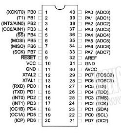
The AVR microcontroller, Atmega32 is a low-power, efficient, and high-performance integrated chip that comprises of an advanced virtual RISC architecture. It can interpret 6 million instructions per second (MIPS). AVR Atmega32 is a 40-pin integrated chip in which 32 pins are input/output pins in the form of four ports: PORTA, PORTB, PORTC, and PORTD, and others are voltage supply, ground, analog reference, crystal oscillator, and reset pins. Each port provides a bi-directional I/O interface and comprises 8 pins, each of which is 8 bits wide.
Interface Functions of AVR Microcontroller
| Interface and pins | Function |
|---|---|
| Reset | This pin is in the active-low configuration. It activates at 0 volts and resets the microcontroller to its initial state. |
| PORTA | Converts analog values to digital language so ATMEGA32 can understand. |
| ADC | Pins A0 to A7 are ADC pins. |
| AREF | The reference voltage pin is used as an external reference for ADC pins. |
| AVCC | Supplies voltage to the ADC pins. |
| GND | Two pins act as GND for ATMEGA32. |
| VCC | The main supply is 5 volts DC for ATMEGA32. |
| Frequency | The operating frequency is 16 MHz; for this, a crystal oscillator is connected to XTAL1 and XTAL2 using a 22 pF capacitor. |
| TWI interface | This interface provides serial communication through two bi-directional bus lines. |
| JTAG | Useful for programming, single-step testing, and debugging the ATMEGA32. |
| ISP | Useful for programming using dedicated pins. |
| SPI | Provides serial communication between ATMEGA32 and other devices. |
AVR Microcontroller Pinout
The following table will help you in understanding the functions of each and every pin.
| PIN NO. | PIN NAME | PIN FUNCTIONS |
|---|---|---|
| 1 | XCK/T0/PBO | T0 -Timer 0 external counter input or XCK- USART clock I/O or PB0-I/O pin 0 of PORTB |
| 2 | PB1/T1 | Timer 1 external counter input or I/O pin 1 of PORTB |
| 3 | PB2/INT2/AIN0 | PB2-I/O pin 2 of PORTB or INT2-external interrupt 2 or AIN0-analog comparator |
| 4 | PB3/OC0/AIN1 | PB3-I/O pin 3 of PORTB or OC0-timer0 output or AIN1-analog comparator |
| 5 | PB4/SS | I/O pin 4 of PORTB or ISP & SPI |
| 6 | PB5/MOSI | I/O pin 5 of PORTB or ISP & SPI |
| 7 | PB6/MISO | I/O pin 6 of PORTB or ISP & SPI |
| 8 | PB7/SCK | I/O pin 7 of PORTB or ISP & SPI |
| 9 | RESET | active low, RESET pin |
| 10 | VCC | Main supply (5 volts DC) |
| 11 | GND | Ground |
| 12 | XTAL1 | for providing input to the inverting clock oscillator and internal clock operating circuit |
| 13 | XTAL2 | output from the inverting oscillator amplifier |
| 14 | PD0/RXD | I/O pin 0 of PORTD or USART serial communication interface |
| 15 | PD1/TXD | I/O pin 1 of PORTD or USART serial communication interface |
| 16 | PD2/INT0 | I/O pin 2 of PORTD or external interrupt 0 |
| 17 | PD3/INT1 | I/O pin 3 of PORTD or external interrupt 1 |
| 18 | PD4/OC1B | I/O pin 4 of PORTD or PWM channel |
| 19 | PD5/OC1A | I/O pin 5 of PORTD or PWM channel |
| 20 | PD6/OCIB | I/O pin 6 of PORTD or timer/counter 1 input |
| 21 | PD7/ICP1 | I/O pin 7 of PORTD or timer/counter 2 output |
| 22 | PC0/SCL | I/O pin 0 of PORTC or TWI interface |
| 23 | PC1/SDA | I/O pin 1 of PORTC or TWI interface |
| 24 | PC2/TCK | I/O pin 2 of PORTC or JTAG interface |
| 25 | PC3/TMS | I/O pin 3 of PORTC or JTAG interface |
| 26 | PC4/TD0 | I/O pin 4 of PORTC or JTAG interface |
| 27 | PC5/TDI | I/O pin 5 of PORTC or JTAG interface |
| 28 | PC6/TOSC1 | I/O pin 6 of PORTC or timer oscillator pin1 |
| 29 | PC7/TOSC2 | I/O pin 7 of PORTC or timer oscillator pin2 |
| 30 | AVCC | voltage supply for ADC |
| 31 | GND | Ground |
| 32 | AREF | analog reference pin for ADC |
| 33-40 | PA0/ADC0 – PA7/ADC7 | I/O PORTA or 8 channel, 10-bit wide ADC |
AVR ATMEGA32 Programming Strategy
The AVR ATMEGA32 is a programmable integrated chip, which is why it is necessary to program ATMEGA32 to operate it for the required applications. For the programming of an AVR microcontroller, the simplest way is to use AVR Studio.
AVR Studio
AVR Studio is an integrated development environment by ATMEL for developing different applications as per requirements. We can use C or assembly language to build up codes for AVR microcontrollers.
To build a project on AVR Studio, follow the steps below:
- First, open the AVR Studio and select the “New Project” option.
- Enter the project name and select AVR GCC; enter the location; then click “next”.
- Select your debug platform (AVR simulator) and required device (AtmegaXX) and click “Finish”.
- A window will open; click the “project” button, go to the configuration option, select the required options, and click “OK”.
- Write the code in the main window.
- For compilation, select the build button and go to the compile option. In the event of an error, compiling will fail.
After the generation of the HEX file, store the program on the AVR microcontroller. For this, you have to dump the HEX file into AVR by using the programmer. The common programmers used for AVR microcontrollers are AVRISP and AVRISP2.
AVR Microcontrollers Applications
AVR microcontroller can be used for any type of project application such as:
| Signal Sensing | Data Acquisition |
| Motion Control | Interface motors |
| LCD Displays | Interface sensors and transducers |
| Interface GSM and GPS systems | Automation and control of industrial plants. |
| Automation of electrical and mechanical systems. | Automation of heavy machines |
| Development of UAVs (Unmanned Aerial Vehicles) |
Conclusion
In this article we have discussed the following topics:
- AVR Microcontroller and its history.
- Features of AVR Microcontroller.
- Architecture of AVR Microcontroller.
- Pinout of AVR Microcontroller.
- Getting started with AVR Studio.
You may also like to read about other AVR Microcontrollers:
Related Articles
If you liked reading this article, there are similar articles provided in the list below:
- AVR microcontroller tutorials for beginners.
- How to use timers of AVR microcontroller.
- LCD interfacing with ATMEGA32 AVR microcontroller.
- How to use push button with ATMEGA32 AVR microcontroller.
- ATMega32 Microcontroller.
In the next tutorial, we will talk about AVR Studio 6 and how to create our first project using AVR Studio 6. For more information, keep visiting our blog. In case you face any issues, leave a comment below.
Can I use ATmega32A to control a fan, heater, led, and PMDC motor, while the microcontroller is interfaced with a temperature and humidity sensor and an LCD?
yes you can use
Thank you so much Farida to share with us such great topic